

 Manufacturers
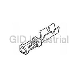
TE CONNECTIVITY 102128-1
Description
Contact SKT Crimp ST Cable Mount 22-26AWG Loose
102128-1
Part Number
102128-1
Price
Request Quote
Manufacturer
TE CONNECTIVITY
Lead Time
Request Quote
Category
Connectors » Connector Contact
Specifications
Manufacturer
TE Connectivity
Manufacturers Part #
102128-1
Industry Aliases
102128-1
Sub-Category
Connector Contacts
Selling Alternatives
87809-1
Brand
AMP
Factory Pack Quantity
1000
Datasheet
DDEController?Action=showdoc&DocId=Catalog+Section%7F1307819_SECTION_5_CONT%7F0808%7Fpdf%7FEnglish%7FENG_CS_1307819_SECTION_5_CONT_0808.pdf
4302 KiB

Extracted Text
Vertical Mount, Receptacle Assemblies AMPMODU Interconnection System Mod IV Receptacle Assemblies, Single-Row, Outrigger Design .100 x .100 [2.54 x 2.54] Centerline, End To End Stackable .125±.010 Dual Entry, End Stackable, [3.17±0.25] Low Profile, .100 x .100 Typ. [2.54 x 2.54] Centerline, .200 [5.08] Tine Spacing .020 [0.51] .245 (Standoffs) [6.22] .148 A Point of [3.77] Contact Typ. .107 .200±.003 [2.72] [5.08±0.08] (Localized Gold Typ. Plate Area) Material and Finish Housing — Glass-filled thermoplastic, black, 94V-0 rated .140 .053 .100 [3.56] [1.34] Plating A — Duplex .000030 [0.00076] [2.54] Typ. gold on contact area, .000150-0.000300 Typ. [0.00381-0.00762] matte tin on solder B area all over .000050 [0.00127] nickel +.005 .075 Plating B — Duplex .000010 -.000 +0.13 [0.000254] gold on contact area, 1.90 [ -.000 ] .000150-.000300 [0.00381-0.00762] matte tin on solder area all over .000050 [0.00127] nickel .200 [5.08] Plating C — .000150-.000300 .140 [0.00381-0.00762] matte tin on solder [3.56] leads, all over .000050 [0.00127] nickel .100 [2.54] .035±.003 Dia. Typ. [0.89±0.08] Recommended PC Board Hole Layout 5 Dimensions Contact Plating/Part Nos. No. of Pos. A B Plating A Plating B Plating C 3 .300 [7.62] .200 [5.08] 5-147720-2 5-147726-2 5-147727-2 4 .400 [10.16] .300 [7.62] 5-147720-3 5-147726-3 5-147727-3 5 .500 [12.70] .400 [10.16] 5-147720-4 5-147726-4 5-147727-4 6 .600 [15.24] .500 [12.70] 5-147720-5 5-147726-5 5-147727-5 7 .700 [17.78] .600 [15.24] 5-147720-6 5-147726-6 5-147727-6 8 .800 [20.32] .700 [17.78] 5-147720-7 5-147726-7 5-147727-7 9 .900 [22.86] .800 [20.32] 5-147720-8 5-147726-8 5-147727-8 10 1.000 [25.40] .900 [22.86] 5-147720-9 5-147726-9 5-147727-9 11 1.100 [27.94] 1.000 [25.40] 6-147720-0 6-147726-0 6-147727-0 12 1.200 [30.48] 1.100 [27.94] 6-147720-1 6-147726-1 6-147727-1 13 1.300 [33.02] 1.200 [30.48] 6-147720-2 6-147726-2 6-147727-2 14 1.400 [35.56] 1.300 [33.02] 6-147720-3 6-147726-3 6-147727-3 15 1.500 [38.10] 1.400 [35.56] 6-147720-4 6-147726-4 6-147727-4 16 1.600 [40.64] 1.500 [38.10] 6-147720-5 6-147726-5 6-147727-5 17 1.700 [43.18] 1.600 [40.64] 6-147720-6 6-147726-6 6-147727-6 18 1.800 [45.72] 1.700 [43.18] 6-147720-7 6-147726-7 6-147727-7 19 1.900 [48.26] 1.800 [45.72] 6-147720-8 6-147726-8 6-147727-8 20 2.000 [50.80] 1.900 [48.26] 7-147720-8 7-147726-8 7-147727-8 30 3.000 [76.20] 2.900 [73.66] 8-147720-8 8-147726-8 8-147727-8 40 4.000 [101.60] 3.900 [99.06] 8-147720-9 8-147726-9 8-147727-9 Notes: 1. Tyco Electronics recommends mating gold or duplex plated headers with duplex plated receptacle assemblies. 2. To obtain the minimum mating post length, add .020 [0.51] (not including the post lead in chamfer) to the maximum point-of-contact dimension and add .062 [1.57] for recommended board thickness if used in Note: All part numbers are RoHS bottom entry application. compliant. 181 Catalog 1307819 Dimensions are in inches and Dimensions are shown for USA: 1-800-522-6752 South America: 55-11-2103-6000 Revised 8-08 millimeters unless otherwise reference purposes only. Canada: 1-905-470-4425 Hong Kong: 852-2735-1628 specified. Values in brackets Specifications subject Mexico: 01-800-733-8926 Japan: 81-44-844-8013 www.tycoelectronics.com are metric equivalents. to change. C. America: 52-55-1106-0803 UK: 44-8706-080-208 AMPMODU Interconnection System Mod IV Receptacle Assemblies, Double-Row, Outrigger Design, .100 x .100 [2.54 x 2.54] Centerline, End to End Stackable Dual Entry, End Stackable, .020 [0.51] Low Profile, .100 x .100 (Standoffs) [2.54 x 2.54] Centerline, .300 [7.62] Tine Spacing .245 [6.22] Typ. A .148 Point of .050 [3.77] Contact [1.27] Typ. Max. Typ. .107 [2.72] Typ. .100±.003 (Localized Gold Material and Finish [2.54±0.08] Plate Area) .300 Housing — Glass-filled thermoplastic, .198 [7.62] [5.03] black, 94V-0 rated Typ. Contacts — Phosphor bronze, plated as follows: .125±.010 Plating A — Duplex .000030 [0.00076] [3.17±0.25] .100 gold on contact area, .000150-.000300 [2.54] [0.00381-0.00762] matte tin on solder Typ. .100 area all over .000050 [0.00127] nickel B [2.54] Plating B — Duplex .000010 Typ. [0.000254] gold on contact area, .100 .100 .000150-.000300 [0.00381-0.00762] [2.54] [2.54] matte tin on solder area all over .000050 Typ. Typ. [0.00127] nickel Plating C — .000150-.000300 [0.00381-0.00762] matte tin on solder leads, all over .000050 [0.00127] nickel Related Product Data +.005 .100 5 .075 Mateable Headers — Dia. -0.00 [2.54] Dia. .035 Refer to the Mating Post Selection ±.003 .060 Typ. +0.13 Typ. 1.90 [0.89 ] Typ. [ ] ±0.08 -0.00 Guide — page 90 Recommended PC Board Hole Layout Performance Characteristics — page 174 Dimensions Contact Plating/Part Nos. No. of Pos. A B Plating A Plating B Plating C 2 .100 [2.54] — 6-534267-3 5-147099-1 8-147100-9 Technical Documents — page 276 4 .200 [5.08] .100 [2.54] 6-534267-7 5-147099-2 9-147100-0 Product Specification 6 .300 [7.62] .200 [5.08] 6-534267-4 5-147099-3 5-147100-1 108-25022 8 .400 [10.16] .300 [7.62] 5-534267-5 5-147099-4 5-147100-2 Application Specification 14 .700 [17.78] .600 [15.24] 5-534267-1 5-147099-7 5-147100-5 114-25018 18 .900 [22.86] .800 [20.32] 6-534267-0 5-147099-9 5-147100-7 20 1.000 [25.40] .900 [22.86] 5-534267-2 6-147099-0 5-147100-8 Additional receptacle assembly sizes are available; minimum 24 1.200 [30.48] 1.100 [27.94] 5-534267-9 6-147099-2 6-147100-0 order quantities may apply. 30 1.500 [38.10] 1.400 [35.56] 6-534267-2 6-147099-5 6-147100-3 Consult Tyco Electronics. 36 1.800 [45.72] 1.700 [43.18] 6-534267-5 6-147099-8 6-147100-6 40 2.000 [50.80] 1.900 [48.26] 5-534267-7 7-147099-0 6-147100-8 48 2.400 [60.96] 2.300 [58.42] 6-534267-1 7-147099-4 7-147100-2 Keying Plug 50 2.500 [63.50] 2.400 [60.96] 6-534267-8 7-147099-5 7-147100-3 60 3.000 [76.20] 2.900 [73.66] 5-534267-8 8-147099-0 7-147100-8 76 3.800 [96.52] 3.700 [93.98] 6-534267-6 8-147099-8 8-147100-6 80 4.000 [101.60] 3.900 [99.06] 5-534267-4 9-147099-0 8-147100-8 Notes: 1. Tyco Electronics recommends mating gold or duplex plated headers with duplex plated receptacle assemblies. Part No. 86286-1 2. To obtain the minimum mating post length, add .020 [0.51] (not including the post lead in chamfer) to the (Plugs into receptacle contact) maximum point-of-contact dimension and .062 for recommended board thickness if used in bottom entry application. Material — Natural color nylon Note: All part numbers are RoHS compliant. 182 Catalog 1307819 Dimensions are in inches and Dimensions are shown for USA: 1-800-522-6752 South America: 55-11-2103-6000 Revised 8-08 millimeters unless otherwise reference purposes only. Canada: 1-905-470-4425 Hong Kong: 852-2735-1628 specified. Values in brackets Specifications subject Mexico: 01-800-733-8926 Japan: 81-44-844-8013 www.tycoelectronics.com are metric equivalents. to change. C. America: 52-55-1106-0803 UK: 44-8706-080-208 Vertical Mount, Receptacle Assemblies Vertical Mount, Receptacle Assemblies AMPMODU Interconnection System Mod. IV Receptacle Assemblies, Double-Row, .100 x .100 [2.54 x 2.54] Centerline .020 Closed Dual Entry, Side and [0.51] End Stackable Low Profile, Typ. (Standoffs) .100 x .100 [2.54 x 2.54] Centerline, .150 [3.81] Tine Spacing .245 [6.22] Typ. A .050 [1.27] Max. Typ. .150 .148 Point of [3.81] [3.77] Material and Finish Contact .100±.003 Typ. Typ. [2.54±0.08] Housing — Glass-filled thermoplastic, .198 black, 94V-0 rated [5.03] Contacts — Phosphor bronze, plated as follows: .107 [2.72] Plating A — Duplex .000030 [0.00076] .130±.010 Typ. [3.30±0.25] gold on contact area, .000150-.000300 .100 (Localized Gold Typ. [0.00381-0.00762] matte tin on solder [2.54] Plate Area) area all over .000050 [0.00127] nickel B Plating B — Duplex .000010 B .100* [0.000254] gold on contact area, +.005 .075 .100 -.000 Dia. [2.54] .100 +0.13 .000150-.000300 [0.00381-0.00762] .060 [2.54] 1.90 - Typ. Typ. [ 0.00] [2.54] Typ. matte tin on solder area all over .000050 Typ. [0.00127] nickel Plating C — .000150-.000300 [0.00381-0.00762] matte tin on solder leads, all over .000050 [0.00127] nickel .150 .035±.003 [3.81] Dia. Typ. Recommended PC Board Hole Layout [0.89±0.08] Typ. for Bottom Entry or Pass Through Applications Related Product Data Recommended PC Board Hole Layout *±.003 [±0.08] tolerances not to accumulate for Top Entry Mateable Headers — within one connector pattern. 5 Refer to the Mating Post Selection Guide — page 90 Dimensions Contact Plating/Part Nos. No. of Pos. Performance Characteristics — A B Plating A Plating B Plating C page 174 2 .100 [2.54] — 5-535542-1 5-147095-1 5-147096-1 4 .200 [5.08] .100 [2.54] 5-535542-2 5-147095-2 5-147096-2 6 .300 [7.62] .200 [5.08] 5-535542-3 5-147095-3 5-147096-3 Technical Documents — page 276 8 .400 [10.16] .300 [7.62] 5-535542-4 5-147095-4 5-147096-4 Product Specification 10 .500 [12.70] .400 [10.16] 5-535542-5 5-147095-5 5-147096-5 108-25022 12 .600 [15.24] .500 [12.70] 5-535542-6 5-147095-6 5-147096-6 14 .700 [17.78] .600 [15.24] 5-535542-7 5-147095-7 5-147096-7 Application Specification 16 .800 [20.32] .700 [17.78] 5-535542-8 5-147095-8 5-147096-8 114-25018 18 .900 [22.86] .800 [20.32] 5-535542-9 5-147095-9 5-147096-9 20 1.000 [25.40] .900 [22.86] 6-535542-0 6-147095-0 6-147096-0 22 1.100 [27.94] 1.000 [25.40] 6-535542-1 6-147095-1 6-147096-1 24 1.200 [30.48] 1.100 [27.94] 6-535542-2 6-147095-2 6-147096-2 26 1.300 [33.02] 1.200 [30.48] 6-535542-3 6-147095-3 6-147096-3 28 1.400 [35.56] 1.300 [33.02] 6-535542-4 6-147095-4 6-147096-4 30 1.500 [38.10] 1.400 [35.56] 6-535542-5 6-147095-5 6-147096-5 32 1.600 [40.64] 1.500 [38.10] 6-535542-6 6-147095-6 6-147096-6 34 1.700 [43.18] 1.600 [40.64] 6-535542-7 6-147095-7 6-147096-7 36 1.800 [45.72] 1.700 [43.18] 6-535542-8 6-147095-8 6-147096-8 38 1.900 [48.26] 1.800 [45.72] 6-535542-9 6-147095-9 6-147096-9 40 2.000 [50.80] 1.900 [48.26] 7-535542-0 7-147095-0 7-147096-0 Notes: 1. Tyco Electronics recommends mating gold or duplex plated headers with duplex plated receptacle assemblies. 2. To obtain the minimum mating post length, add .020 [0.51] (not including the post lead in chamfer) to Note: All part numbers are RoHS the maximum point-of-contact dimension, and .062 [1.57] for recommended board thickness if used in bot- compliant. tom entry application. 183 Catalog 1307819 Dimensions are in inches and Dimensions are shown for USA: 1-800-522-6752 South America: 55-11-2103-6000 Revised 8-08 millimeters unless otherwise reference purposes only. Canada: 1-905-470-4425 Hong Kong: 852-2735-1628 specified. Values in brackets Specifications subject Mexico: 01-800-733-8926 Japan: 81-44-844-8013 www.tycoelectronics.com are metric equivalents. to change. C. America: 52-55-1106-0803 UK: 44-8706-080-208 AMPMODU Interconnection System Mod. IV Receptacle Assemblies, Double-Row, .100 x .100 [2.54 x 2.54] Centerline (Continued) Dimensions Contact Plating/Part Nos. No. of Pos. A B Plating A Plating B Plating C 42 2.100 [53.34] 2.000 [50.80] 7-535542-1 7-147095-1 7-147096-1 44 2.200 [55.88] 2.100 [53.34] 7-535542-2 7-147095-2 7-147096-2 46 2.300 [58.42] 2.200 [55.88] 7-535542-3 7-147095-3 7-147096-3 48 2.400 [60.96] 2.300 [58.42] 7-535542-4 7-147095-4 7-147096-4 50 2.500 [63.50] 2.400 [60.96] 7-535542-5 7-147095-5 7-147096-5 52 2.600 [66.04] 2.500 [63.50] 7-535542-6 7-147095-6 7-147096-6 54 2.700 [68.58] 2.600 [66.04] 7-535542-7 7-147095-7 7-147096-7 56 2.800 [71.12] 2.700 [68.58] 7-535542-8 7-147095-8 7-147096-8 58 2.900 [73.66] 2.800 [71.12] 7-535542-9 7-147095-9 7-147096-9 60 3.000 [76.20] 2.900 [73.66] 8-535542-0 8-147095-0 8-147096-0 62 3.100 [78.74] 3.000 [76.20] 8-535542-1 8-147095-1 8-147096-1 64 3.200 [81.28] 3.100 [78.74] 8-535542-2 8-147095-2 8-147096-2 66 3.300 [83.82] 3.200 [81.28] 8-535542-3 8-147095-3 8-147096-3 68 3.400 [86.36] 3.300 [83.82] 8-535542-4 8-147095-4 8-147096-4 70 3.500 [88.90] 3.400 [86.36] 8-535542-5 8-147095-5 8-147096-5 72 3.600 [91.44] 3.500 [88.90] 8-535542-6 8-147095-6 8-147096-6 74 3.700 [93.98] 3.600 [91.44] 8-535542-7 8-147095-7 8-147096-7 76 3.800 [96.52] 3.700 [93.98] 8-535542-8 8-147095-8 8-147096-8 78 3.900 [99.06] 3.800 [96.52] 8-535542-9 8-147095-9 8-147096-9 80 4.000 [101.60] 3.900 [99.06] 9-535542-0 9-147095-0 9-147096-0 5 Note: All part numbers are RoHS compliant. 184 Catalog 1307819 Dimensions are in inches and Dimensions are shown for USA: 1-800-522-6752 South America: 55-11-2103-6000 Revised 8-08 millimeters unless otherwise reference purposes only. Canada: 1-905-470-4425 Hong Kong: 852-2735-1628 specified. Values in brackets Specifications subject Mexico: 01-800-733-8926 Japan: 81-44-844-8013 www.tycoelectronics.com are metric equivalents. to change. C. America: 52-55-1106-0803 UK: 44-8706-080-208 Vertical Mount, Receptacle Assemblies Surface Mount Receptacle Assemblies AMPMODU Interconnection System Mod IV Surface Mount Vertical Receptacle Assemblies, .100 x .100 [2.54 x 2.54] Centerline Product Facts ■ Surface Mount Leads ■ Contact Material: phosphor bronze ■ High temperature, black thermoplastic housings, 94V-0 rated, capable of withstanding IR or vapor- phase reflow ■ Gold/tin duplex plating for reliable mating interconnection and solder interface ■ Metallic hold downs provide retention in the PC board prior to and during the reflow process … and strain relief after soldering ■ Hold downs provide for proper lead-to-pad registration ■ Closed-entry receptacle The AMPMODU 0.025 [0.64] AMPMODU surface mount downs are soldered during housings provide lead-in square interconnection vertical receptacle the reflow process and ramp for positive mating system is an industry assemblies continue to serve as a strain relief for ■ Receptacle contacts employ standard that has provided provide the proven features the solder joints during dual cantilever beams for level III and IV thru-hole and benefits of their mating/unmating. reliable connections interconnections to almost thru-hole counterparts in the The design of the hold every industry and AMPMODU product family. ■ Recognized under the downs results in an marketplace for years. Closed-entry style housing Component Program excellent ratio of As technology advances, design provides a lead-in of Underwriters insertion/extraction forces so has the AMPMODU ramp for positive mating of Laboratories Inc. R (into the PC board); 20 lb. product line. contacts, virtually eliminating File No. E28476 [89 N] maximum insertion 5 the possibility of stubbing. Surface mount vertical force per pair and 10 lb. ■ Certified by The dual-beam receptacle receptacle assemblies are [44.5 N] minimum extraction Canadian Standards contact design, coupled with available to meet your level force per pair (unsoldered). Association, R gold plating in the contact II packaging needs as No tools are required for File No. LR 7189 area, provides a reliable process technologies insertion. interface. Tin plating on the evolve from wave soldering solder tails also enhances to surface mount reflow solderability. (infrared and vapor-phase) processes. AMPMODU The incorporation of surface mount receptacle compliant metallic hold assemblies are offered in downs on receptacle vertical dual entry assemblies offers multiple configurations. These benefits. The hold downs receptacles are available in provide for proper lead-to- single-row and double-row pad registration and provide configurations with a retention to the PC board contact centerline spacing prior to and during of .100 x .100 [2.54 x 2.54]. processing. Used with a plated thru-hole, the hold 185 Catalog 1307819 Dimensions are in inches and Dimensions are shown for USA: 1-800-522-6752 South America: 55-11-2103-6000 Revised 8-08 millimeters unless otherwise reference purposes only. Canada: 1-905-470-4425 Hong Kong: 852-2735-1628 specified. Values in brackets Specifications subject Mexico: 01-800-733-8926 Japan: 81-44-844-8013 www.tycoelectronics.com are metric equivalents. to change. C. America: 52-55-1106-0803 UK: 44-8706-080-208 AMPMODU Interconnection System Mod IV Surface Mount Vertical Receptacle Assemblies, .100 x .100 [2.54 x 2.54] Centerline (Continued) Voltage Rating: 250 VAC Performance Specifications Current Rating: 3.0 amperes (max.) for single contact; 2.0 amperes (max.) per contact when connector is fully energized Operating Temperature Range (Receptacle Assemblies): –65°C to +125°C Operating Temperature Range (Headers): -65°C to +105°C Dielectric Withstanding Voltage: 750 VAC Termination Resistance: 12 milliohms (max.) Insulation Resistance: 5000 megohms (min.) Mating Force (Receptacle Assemblies): 9.0 oz. [2.50N] (max.) per contact Unmating Force (Receptacle Assemblies): 1.5 oz. [0.42N] (min.) per contact Durability: Tested to 200 cycles (min.) for .000030 [0.00076] gold plated contacts 5 186 Catalog 1307819 Dimensions are in inches and Dimensions are shown for USA: 1-800-522-6752 South America: 55-11-2103-6000 Revised 8-08 millimeters unless otherwise reference purposes only. Canada: 1-905-470-4425 Hong Kong: 852-2735-1628 specified. Values in brackets Specifications subject Mexico: 01-800-733-8926 Japan: 81-44-844-8013 www.tycoelectronics.com are metric equivalents. to change. C. America: 52-55-1106-0803 UK: 44-8706-080-208 Surface Mount Receptacle Assemblies Surface Mount Receptacle Assemblies AMPMODU Interconnection System Mod IV Receptacle Assemblies, Single-Row, Surface Mount, .100 [2.54] Centerline with Compliant Pin Hold Downs .030 0.76 .020 Standoffs Surface Mount, Single-Row, .038 [ ] .025 0.64 [0.51] Typ. [0.97] Dual Entry with Compliant Typ. Pin Holddowns .265 [6.73] Typ. .107 (Localized Gold D [2.72] Plate Area) C Material and Finish .208 .140 Max. [5.28] Housing — Glass-filled thermoplastic, [3.56] (Depressed) black, 94V-0 rated Contacts — Phosphor bronze, plated .100 Typ. [2.54] as follows: .148 Point of A [3.77] Contact Plating A — Duplex .000030 D [0.00076] gold on contact area, .100 B .000150-.000300 [0.00381-0.00762] [2.54] matte tin on solder area all over .000050 P.C. Board .069 [0.00127] nickel [1.75] Plating B — Duplex .000010 .228 [0.000254] gold on contact area, [5.78] .075 .000150-.000300 [0.00381-0.00762] [1.91] matte tin on solder area all over .000050 [0.00127] nickel .090 Typ. [2.28] .042±.003 Plating C — .000150-.000300 .110 Dia. [1.07±0.08] [2.79] [0.00381-0.00762] matte tin on solder .042±.003 Dia. leads, all over .000050 [0.00127] nickel .040±.003 [1.07±0.08] C .060 [1.02±0.08] Min. [1.52] .042±.003 Dia. Typ. Dia. Related Product Data [1.07±0.08] (For bottom Recommended PC Board Pad Pattern entry or pass (.008 [0.20] thick stencil) Mateable Headers — thru applica- Refer to Mating Post Selection Guide — tions) page 90 Performance Specifications — page 186 Packaged in Tubes Packaged in Tape & Reel No. of Dimensions Contact Plating/ Part Nos. Contact Plating/ Part Nos. 5 Pos. AB C D Plating A Plating B Plating C Plating A Plating B Plating C 3 .500 [12.70] .200 [5.08] See note 3 .400 [10.16] 5-147744-1 5-147743-1 5-147742-1 5-147724-1 5-147730-1 5-147731-1 4 .600 [15.24] .300 [7.62] See note 3 .500 [12.70] 5-147744-2 5-147743-2 5-147742-2 5-147724-2 5-147730-2 5-147731-2 5 .700 [17.78] .400 [10.16] See note 3 .600 [15.24] 5-147744-3 5-147743-3 5-147742-3 5-147724-3 5-147730-3 5-147731-3 6 .800 [20.32] .500 [12.70] See note 3 .700 [17.78] 5-147744-4 5-147743-4 5-147742-4 5-147724-4 5-147730-4 5-147731-4 7 .900 [22.86] .600 [15.24] See note 3 .800 [20.32] 5-147744-5 5-147743-5 5-147742-5 5-147724-5 5-147730-5 5-147731-5 8 1.000 [25.40] .700 [17.78] See note 3 .900 [22.86] 5-147744-6 5-147743-6 5-147742-6 5-147724-6 5-147730-6 5-147731-6 9 1.100 [27.94] .800 [20.32] See note 3 1.000 [25.40] 5-147744-7 5-147743-7 5-147742-7 5-147724-7 5-147730-7 5-147731-7 10 1.200 [30.48] .900 [22.86] See note 3 1.100 [27.94] 5-147744-8 5-147743-8 5-147742-8 5-147724-8 5-147730-8 5-147731-8 11 1.300 [33.02] 1.000 [25.40] See note 3 1.200 [30.48] 5-147744-9 5-147743-9 5-147742-9 5-147724-9 5-147730-9 5-147731-9 12 1.400 [35.56] 1.100 [27.94] See note 3 1.300 [33.02] 6-147744-0 6-147743-0 6-147742-0 6-147724-0 6-147730-0 6-147731-0 13 1.500 [38.10] 1.200 [30.48] See note 3 1.400 [35.56] 6-147744-1 6-147743-1 6-147742-1 6-147724-1 6-147730-1 6-147731-1 14 1.600 [40.64] 1.300 [33.02] See note 3 1.500 [38.10] 6-147744-2 6-147743-2 6-147742-2 6-147724-2 6-147730-2 6-147731-2 15 1.700 [43.18] 1.400 [35.56] See note 3 1.600 [40.64] 6-147744-3 6-147743-3 6-147742-3 6-147724-3 6-147730-3 6-147731-3 16 1.800 [45.72] 1.500 [38.10] See note 3 1.700 [43.18] 6-147744-4 6-147743-4 6-147742-4 6-147724-4 6-147730-4 6-147731-4 17 1.900 [48.26] 1.600 [40.64] See note 3 1.800 [45.72] 6-147744-5 6-147743-5 6-147742-5 6-147724-5 6-147730-5 6-147731-5 18 2.000 [50.80] 1.700 [43.18] See note 3 1.900 [48.26] 6-147744-6 6-147743-6 6-147742-6 6-147724-6 6-147730-6 6-147731-6 19 2.100 [53.34] 1.800 [45.72] See note 3 2.000 [50.80] 6-147744-7 6-147743-7 6-147742-7 6-147724-7 6-147730-7 6-147731-7 20 2.200 [55.88] 1.900 [48.26] See note 3 2.100 [53.34] 6-147744-8 6-147743-8 6-147742-8 6-147724-8 6-147730-8 6-147731-8 30 3.200 [81.28] 2.900 [73.66] See note 3 3.100 [78.74] 7-147744-8 7-147743-8 7-147742-8 7-147724-8 7-147730-8 7-147731-8 40 4.300 [109.22] 4.100 [104.14] 2.100 [53.34] 4.200 [106.68] 8-147744-8 8-147743-8 8-147742-8 8-147724-8 8-147730-8 8-147731-8 Notes: 1. Tyco Electronics recommends mating gold or duplex plated headers with duplex plated receptacle assemblies. 2. To obtain the minimum mating post length, add .020 [0.51] (not including the post lead in chamfer) to the maximum point-of-contact dimension, and .062 [1.57] for recommended board thickness if used in bottom entry application 3. No center hold down. Note: All part numbers are RoHS compliant. 187 Catalog 1307819 Dimensions are in inches and Dimensions are shown for USA: 1-800-522-6752 South America: 55-11-2103-6000 Revised 8-08 millimeters unless otherwise reference purposes only. Canada: 1-905-470-4425 Hong Kong: 852-2735-1628 specified. Values in brackets Specifications subject Mexico: 01-800-733-8926 Japan: 81-44-844-8013 www.tycoelectronics.com are metric equivalents. to change. C. America: 52-55-1106-0803 UK: 44-8706-080-208 AMPMODU Interconnection System Mod IV Receptacle Assemblies, Single-Row, Surface Mount, .100 [2.54] x .100 [2.54] Centerline End To End Stackable without Compliant Pin Holddowns .020 Standoff Typ. Surface Mount,Single-Row, [0.51] Dual Entry, End to End Stackable .265 [6.73] .107 .208 A [2.72] Max. Material and Finish [5.28] Typ. .100 Typ. (Localized Gold Housing — Glass-filled thermoplastic, [2.54] Plate Area) black, 94V-0 rated Contacts — Phosphor bronze, plated .140 as follows: [3.56] Plating A — Duplex .000030 [0.00076] gold on contact area, .000150-.000300 [0.00381-0.00762] Point of .148 matte tin on solder area all over .000050 Contact [3.77] [0.00127] nickel Plating B — Duplex .000010 [0.000254] gold on contact area, .040±.003 B Dia. Typ. [1.02±0.08] .000150-.000300 [0.00381-0.00762] (For bottom entry or pass matte tin on solder area all over .000050 .100 through applications) [0.00127] nickel [2.54] Plating C — .000150-.000300 [0.00381-0.00762] matte tin on solder leads, all over .000050 [0.00127] nickel .228 [5.78] Related Product Data Mateable Headers — .060 Min. Refer to Mating Post Selection Guide — [1.52] .090 page 90 [2.28] Recommended PC Board Pad Pattern Performance Specifications — (.008 [0.20] thick stencil) page 186 5 Packaged in Tubes Packaged in Tape & Reel No. of Dimensions Contact Plating/ Part Nos. Contact Plating/ Part Nos. Pos. AB Plating A Plating B Plating C Plating A Plating B Plating C 3 .300 [7.62] .200 [5.08] 5-147738-2 5-147737-2 5-147736-2 5-147723-2 5-147728-2 5-147729-2 4 .400 [10.16] .300 [7.62] 5-147738-3 5-147737-3 5-147736-3 5-147723-3 5-147728-3 5-147729-3 5 .500 [12.70] .400 [10.16] 5-147738-4 5-147737-4 5-147736-4 5-147723-4 5-147728-4 5-147729-4 6 .600 [15.24] .500 [12.70] 5-147738-5 5-147737-5 5-147736-5 5-147723-5 5-147728-5 5-147729-5 7 .700 [17.78] .600 [15.24] 5-147738-6 5-147737-6 5-147736-6 5-147723-6 5-147728-6 5-147729-6 8 .800 [20.32] .700 [17.78] 5-147738-7 5-147737-7 5-147736-7 5-147723-7 5-147728-7 5-147729-7 9 .900 [22.86]] .800 [20.32] 5-147738-8 5-147737-8 5-147736-8 5-147723-8 5-147728-8 5-147729-8 10 1.000 [25.40] .900 [22.86] 5-147738-9 5-147737-9 5-147736-9 5-147723-9 5-147728-9 5-147729-9 11 1.100 [27.94] 1.000 [25.40] 6-147738-0 6-147737-0 6-147736-0 6-147723-0 6-147728-0 6-147729-0 12 1.200 [30.48] 1.100 [27.94] 6-147738-1 6-147737-1 6-147736-1 6-147723-1 6-147728-1 6-147729-1 13 1.300 [33.02] 1.200 [30.48] 6-147738-2 6-147737-2 6-147736-2 6-147723-2 6-147728-2 6-147729-2 14 1.400 [35.56] 1.300 [33.02] 6-147738-3 6-147737-3 6-147736-3 6-147723-3 6-147728-3 6-147729-3 15 1.500 [38.10] 1.400 [35.56] 6-147738-4 6-147737-4 6-147736-4 6-147723-4 6-147728-4 6-147729-4 16 1.600 [40.64] 1.500 [38.10] 6-147738-5 6-147737-5 6-147736-5 6-147723-5 6-147728-5 6-147729-5 17 1.700 [43.18] 1.600 [40.64] 6-147738-6 6-147737-6 6-147736-6 6-147723-6 6-147728-6 6-147729-6 18 1.800 [45.72] 1.700 [43.18] 6-147738-7 6-147737-7 6-147736-7 6-147723-7 6-147728-7 6-147729-7 19 1.900 [48.26] 1.800 [45.72] 6-147738-8 6-147737-8 6-147736-8 6-147723-8 6-147728-8 6-147729-8 20 2.000 [50.80] 1.900 [48.26] 6-147738-9 6-147737-9 6-147736-9 6-147723-9 6-147728-9 6-147729-9 30 3.000 [76.20] 2.900 [73.66] 7-147738-9 7-147737-9 7-147736-9 7-147723-9 7-147728-9 7-147729-9 40 4.000 [101.60] 3.900 [99.06] 8-147738-9 8-147737-9 8-147736-9 8-147723-9 8-147728-9 8-147729-9 Notes: 1. Tyco Electronics recommends mating gold or duplex plated headers with duplex plated receptacle assemblies. 2. To obtain the minimum mating post length, add .020 [0.51] (not including the post lead in chamfer) to the maximum point-of-contact dimension, and .062 [1.57] for recommended board thickness if used in bottom entry application. Note: All part numbers are RoHS compliant. 188 Catalog 1307819 Dimensions are in inches and Dimensions are shown for USA: 1-800-522-6752 South America: 55-11-2103-6000 Revised 8-08 millimeters unless otherwise reference purposes only. Canada: 1-905-470-4425 Hong Kong: 852-2735-1628 specified. Values in brackets Specifications subject Mexico: 01-800-733-8926 Japan: 81-44-844-8013 www.tycoelectronics.com are metric equivalents. to change. C. America: 52-55-1106-0803 UK: 44-8706-080-208 Surface Mount Receptacle Assemblies Surface Mount Receptacle Assemblies AMPMODU Interconnection System Mod IV Surface Mount Receptacle Assemblies, Double-Row, .100 x .100 [2.54 x 2.54] Centers Surface Mount,Double Row, Dual Entry with Holddowns A .100 .050 [2.54] [1.27] Typ. Typ. .198 [5.03] .107 .148 [2.72] Point of .265 [3.76] Typ. Contact [6.73] Typ. (Localized Gold Material and Finish Typ. Plate Area) Housing — Glass-filled thermoplastic, black, 94V-0 rated .083 Contacts — Phosphor bronze, plated [2.12] as follows: Typ. Plating A — Duplex .000030 [0.00076] .020 gold on contact area, .000150-.000300 .027±.002 [0.51] Typ. [0.69±0.05] Typ. .266 [0.00381-0.00762] matte tin on solder [6.75] area all over .000050 [0.00127] nickel Plating B — Duplex .000010 .110 [0.000254] gold on contact area, [2.79] Typ. .000150-.000300 [0.00381-0.00762] .238 B [6.05] matte tin on solder area all over .000050 Typ. [0.00127] nickel .040±.003 .100 [1.02±0.08] Plating C — .000150-.000300 .100 Typ. [2.54] [2.54] [0.00381-0.00762] matte tin on solder Typ. leads, all over .000050 [0.00127] nickel .004 [0.10] Related Product Data Typ. .075 Mateable Headers — .090 [1.91] [2.29] Refer to Mating Post Selection Guide — Typ. Typ. page 90 .040 [1.02] Performance Specifications — .040±.003 Typ. D page 186 [1.02±0.08] (For bottom entry or 5 .060 pass thru applications) [1.52] Typ. Technical Documents — page 276 C Product Specification Recommended PC Board Layout 108-25022 (.008 [0.20] thick stencil) Application Specification 114-25018 Additional receptacle assembly sizes are available; minimum order quantities may apply. Consult Tyco Electronics. Keying Plug P Pa ar rt t No. No. 86286-1 86286-1 (Plugs into receptacle contact) (Plugs into receptacle contact) Material — Natural color nylon Note: All part numbers are RoHS compliant. 189 Catalog 1307819 Dimensions are in inches and Dimensions are shown for USA: 1-800-522-6752 South America: 55-11-2103-6000 Revised 8-08 millimeters unless otherwise reference purposes only. Canada: 1-905-470-4425 Hong Kong: 852-2735-1628 specified. Values in brackets Specifications subject Mexico: 01-800-733-8926 Japan: 81-44-844-8013 www.tycoelectronics.com are metric equivalents. to change. C. America: 52-55-1106-0803 UK: 44-8706-080-208 AMPMODU Interconnection System Mod IV Surface Mount Receptacle Assemblies, Double-Row, .100 x .100 [2.54 x 2.54] Centers (Continued) Packaged in Tubes Packaged in Tape and Reel Dimensions No. of Contact Plating/Part Nos. Contact Plating/Part Nos. A BCD Pos. Plating A Plating B Plating C Plating A Plating B Plating C 10 .700 [17.78] .400 [10.16] .600 [15.24] See Note 1 5-147102-5 5-147101-5 5-147103-5 5-147747-5 5-147746-5 5-147745-5 14 .900 [22.86] .600 [15.24] .800 [20.32] See Note 1 5-147102-7 5-147101-7 5-147103-7 5-147747-7 5-147746-7 5-147745-7 20 1.200 [30.48] .900 [22.86] 1.100 [27.94] See Note 1 6-147102-0 6-147101-0 6-147103-0 6-147747-0 6-147746-0 6-147745-0 22 1.300 [33.02] 1.000 [25.40] 1.200 [30.48] See Note 1 6-147102-1 6-147101-1 6-147103-1 6-147747-1 6-147746-1 6-147745-1 26 1.500 [38.10] 1.200 [30.48] 1.400 [35.56] See Note 1 6-147102-3 6-147101-3 6-147103-3 6-147747-3 6-147746-3 6-147745-3 30 1.700 [43.18] 1.400 [35.56] 1.600 [40.64] See Note 1 6-147102-5 6-147101-5 6-147103-5 6-147747-5 6-147746-5 6-147745-5 34 1.900 [48.26] 1.600 [40.64] 1.800 [45.72] See Note 1 6-147102-7 6-147101-7 6-147103-7 6-147747-7 6-147746-7 6-147745-7 36 2.000 [50.08] 1.700 [43.18] 1.900 [48.26] See Note 1 6-147102-8 6-147101-8 6-147103-8 6-147747-8 6-147746-8 6-147745-8 40 2.200 [55.88] 1.900 [48.26] 2.100 [53.34] See Note 1 7-147102-0 7-147101-0 7-147103-0 7-147747-0 7-147746-0 7-147745-0 46 2.500 [63.50] 2.200 [55.88] 2.400 [60.96] See Note 1 7-147102-3 7-147101-3 7-147103-3 7-147747-3 7-147746-3 7-147745-3 50 2.700 [68.58] 2.400 [60.96] 2.600 [66.04] See Note 1 7-147102-5 7-147101-5 7-147103-5 7-147747-5 7-147746-5 7-147745-5 62 3.300 [83.82] 3.000 [76.20] 3.200 [81.28] See Note 1 8-147102-1 8-147101-1 8-147103-1 8-147747-1 8-147746-1 8-147745-1 64 3.400 [86.36] 3.100 [78.74] 3.300 [83.82] See Note 1 8-147102-2 8-147101-2 8-147103-2 8-147747-2 8-147746-2 8-147745-2 66 3.500 [88.90] 3.200 [81.28] 3.400 [86.36] See Note 1 8-147102-3 8-147101-3 8-147103-3 8-147747-3 8-147746-3 8-147745-3 70 3.700 [95.98] 3.400 [86.36] 3.600 [91.44] See Note 1 8-147102-5 8-147101-5 8-147103-5 8-147747-5 8-147746-5 8-147745-5 80 4.300 [109.22] 3.900 [99.06] 4.200 [106.68] 2.100 [53.34] 9-147102-0 9-147101-0 9-147103-0 9-147747-0 9-147746-0 9-147745-0 Notes: 1. No center holddown. 2. To obtain the minimum mating post length, add .020 [0.51] (not including the post lead in chamfer) to the maximum point-of-contact dimension and .062 [1.57] for recommended board thickness in bottom entry applications. 5 Note: All part numbers are RoHS compliant. 190 Catalog 1307819 Dimensions are in inches and Dimensions are shown for USA: 1-800-522-6752 South America: 55-11-2103-6000 Revised 8-08 millimeters unless otherwise reference purposes only. Canada: 1-905-470-4425 Hong Kong: 852-2735-1628 specified. Values in brackets Specifications subject Mexico: 01-800-733-8926 Japan: 81-44-844-8013 www.tycoelectronics.com are metric equivalents. to change. C. America: 52-55-1106-0803 UK: 44-8706-080-208 Surface Mount Receptacle Assemblies Surface Mount Receptacle Assemblies AMPMODU Interconnection System Mod IV Surface Mount Receptacle Assemblies, Double-Row, .100 x .100 [2.54 x 2.54] Centerline Surface Mount,Double Row, A Dual Entry .100 Typ. [2.54] End to End Stackable .100 Typ. [2.54] .198±.002 [5.03±0.05] .050 [1.27] Max. .148 Point of .265 .107 [3.76] Contact [6.73] [2.72] Material and Finish Typ. (Localized Gold Housing — Glass-filled thermoplastic, Plate Area) black, 94V-0 rated Contacts — Phosphor bronze, plated as follows: Plating A — Duplex .000030 [0.00076] .020 .027±.002 .266 Typ. [0.51] [0.69±0.05] gold on contact area, .000150-.000300 [6.75] Typ. [0.00381-0.00762] matte tin on solder area all over .000050 [0.00127] nickel Plating B — Duplex .000010 .238 [0.000254] gold on contact area, B [6.05] .000150-.000300 [0.00381-0.00762] .100 Typ. [2.54] matte tin on solder area all over .000050 Typ. [0.00127] nickel .100 Plating C — .000150-.000300 [2.54] Typ. [0.00381-0.00762] tin-lead over .004 .000050 [0.00127] nickel [0.10] Typ. .090 Related Product Data [2.29] .060 Typ. Mateable Headers — [1.52] .040 Typ. Refer to Mating Post Selection Guide — [1.02] page 90 5 Recommended PC Board Pad Layout Performance Specifications — (.008 [0.20] thick stencil) page 186 (for Bottom Entry and Pass Through applications) Technical Documents — page 276 Product Specification 108-25022 Application Specification 114-25018 Additional receptacle assembly sizes are available; minimum order quantities may apply. Consult Tyco Electronics. Keying Plug P Pa ar rt t No. No. 86286-1 86286-1 (Plugs into receptacle contact) (Plugs into receptacle contact) Material — Natural color nylon Note: All part numbers are RoHS compliant. 191 Catalog 1307819 Dimensions are in inches and Dimensions are shown for USA: 1-800-522-6752 South America: 55-11-2103-6000 Revised 8-08 millimeters unless otherwise reference purposes only. Canada: 1-905-470-4425 Hong Kong: 852-2735-1628 specified. Values in brackets Specifications subject Mexico: 01-800-733-8926 Japan: 81-44-844-8013 www.tycoelectronics.com are metric equivalents. to change. C. America: 52-55-1106-0803 UK: 44-8706-080-208 AMPMODU Interconnection System Mod IV Surface Mount Receptacle Assemblies, Double-Row, .100 x .100 [2.54 x 2.54] Centerline (Continued) Packaged in Tubes Packaged in Tape & Reel No. of Dimensions Contact Plating/ Part Nos. Contact Plating/ Part Nos. Pos. AB Plating A Plating B Plating C Plating A Plating B Plating C 10 .500 [12.70] .400 [10.16] 5-147741-5 5-147740-5 5-147739-5 5-147105-5 5-147104-5 5-147106-5 14 .700 [17.78] .600 [15.24] 5-147741-7 5-147740-7 5-147739-7 5-147105-7 5-147104-7 5-147106-7 20 1.000 [25.40] .900 [22.86] 6-147741-0 6-147740-0 6-147739-0 6-147105-0 6-147104-0 6-147106-0 22 1.100 [27.94] 1.000 [25.40] 6-147741-1 6-147740-1 6-147739-1 6-147105-1 6-147104-1 6-147106-1 26 1.300 [33.02] 1.200 [30.48] 6-147741-3 6-147740-3 6-147739-3 6-147105-3 6-147104-3 6-147106-3 30 1.500 [38.10] 1.400 [35.56] 6-147741-5 6-147740-5 6-147739-5 6-147105-5 6-147104-5 6-147106-5 34 1.700 [43.18] 1.600 [40.64] 6-147741-7 6-147740-7 6-147739-7 6-147105-7 6-147104-7 6-147106-7 36 1.800 [45.72] 1.700 [43.18] 6-147741-8 6-147740-8 6-147739-8 6-147105-8 6-147104-8 6-147106-8 40 2.000 [50.80] 1.900 [48.26] 7-147741-0 7-147740-0 7-147739-0 7-147105-0 7-147104-0 7-147106-0 46 2.300 [58.42] 2.200 [55.88] 7-147741-3 7-147740-3 7-147739-3 7-147105-3 7-147104-3 7-147106-3 50 2.500 [63.50] 2.400 [60.96] 7-147741-5 7-147740-5 7-147739-5 7-147105-5 7-147104-5 7-147106-5 62 3.100 [78.74] 3.000 [76.20] 8-147741-1 8-147740-1 8-147739-1 8-147105-1 8-147104-1 8-147106-1 64 3.200 [81.28] 3.100 [78.74] 8-147741-2 8-147740-2 8-147739-2 8-147105-2 8-147104-2 8-147106-2 66 3.300 [83.82] 3.200 [81.28] 8-147741-3 8-147740-3 8-147739-3 8-147105-3 8-147104-3 8-147106-3 70 3.500 [88.90] 3.400 [86.36] 8-147741-5 8-147740-5 8-147739-5 8-147105-5 8-147104-5 8-147106-5 80 4.000 [101.60] 3.900 [99.06] 9-147741-0 9-147740-0 9-147739-0 9-147105-0 9-147104-0 9-147106-0 Notes: 1. To obtain the minimum mating post length, add .020 [0.51] (not including the post lead in chamfer) to the maximum point-of-contact dimension and .062 [1.57] for recommended board thickness in bottom entry applications. 5 Note: All part numbers are RoHS compliant. 192 Catalog 1307819 Dimensions are in inches and Dimensions are shown for USA: 1-800-522-6752 South America: 55-11-2103-6000 Revised 8-08 millimeters unless otherwise reference purposes only. Canada: 1-905-470-4425 Hong Kong: 852-2735-1628 specified. Values in brackets Specifications subject Mexico: 01-800-733-8926 Japan: 81-44-844-8013 www.tycoelectronics.com are metric equivalents. to change. C. America: 52-55-1106-0803 UK: 44-8706-080-208 Surface Mount Receptacle Assemblies Printed Circuit Board Connectors AMPMODU Interconnection System Two-Piece Printed Circuit Board Connectors Product Facts ■ Two-Piece reliability ■ Two- and three-row systems available ■ Short signal path for VLSI applications ■ Receptacles employ dual cantilever beams and built- in anti-overstress to provide reliable connections ■ Built-in guides provide alignment before contact engagement ■ Closed entry receptacle housings provide lead-in ramp for positive mating of contacts ■ Shrouded headers provide full pin protection ■ Polarized headers ■ Vertical headers available with ACTION PIN posts or .025 [0.64] square solder posts ■ Repairable ACTION PIN posts ■ Simple seating tooling for headers with ACTION PIN posts ACTION PIN Posts Solder Posts ■ Recognized under the Component Program of Underwriters 5 Laboratories Inc., R File No. E28476 ■ Certified by Canadian Standards Receptacle Contact Association, R (Double Beam with Anti-Overstress) File No. LR 7189 Board Retention Feature Available 3-Row Closed Entry 3-Row Header Receptacle 5-534974-8 5-103264-3 5-532956-3 Horizontal Receptacle 5-534972-2 Vertical Receptacle 5-102690-3 Double-Row Vertical Header Make First/Break with ACTION PIN Last Header Posts (Part Nos. available upon request) 6-102589-2 3/4 Shroud, Right Angle Header For drawings, technical data or samples, contact your Tyco Electronics sales engi- 5-532956-3 Horizontal Note: All part numbers are RoHS neer or call the Tyco Electronics Product Receptacle compliant. Information Center: 1-800-522-6752 193 Catalog 1307819 Dimensions are in inches and Dimensions are shown for USA: 1-800-522-6752 South America: 55-11-2103-6000 Revised 8-08 millimeters unless otherwise reference purposes only. Canada: 1-905-470-4425 Hong Kong: 852-2735-1628 specified. Values in brackets Specifications subject Mexico: 01-800-733-8926 Japan: 81-44-844-8013 www.tycoelectronics.com are metric equivalents. to change. C. America: 52-55-1106-0803 UK: 44-8706-080-208 AMPMODU Interconnection System Two-Piece Printed Circuit Board Connectors (Continued) AMPMODU Two-Piece The AMPMODU three-row A board retention feature Printed Circuit Board connector system is is offered in the two-row connectors are designed produced in 30 through 300 horizontal receptacles, to reliably and economically positions (straight post two-row right angle headers meet the packaging and headers and mating and two- and three-row interconnection requirements horizontal receptacles). vertical headers. Built-in of today’s sophisticated guides assure accurate Both two- and three-row electronics. header and receptacle vertical headers are alignment before contact The double row system is available with press-fit engagement. produced in 10 thru 200 ACTION PIN posts or positions in the vertical standard .025 [0.64] square Closed entry receptacle headers and horizontal solder posts. There is a housings provide a lead-in receptacles, and 10 thru simple seating tool for ramp for positive mating of 160 positions in the right headers with ACTION PIN contacts. angle headers and vertical posts. receptacles. Temperature Rating — Performance Specifications Headers and Receptacles — Current Rating — –65°C to +125°C (black thermoplastic 3 amperes max. for single contact; housings, 94V-0 rated) 2 amperes max. per contact for fully Durability (Tested to) — 200 cycles energized connector for .000030 [0.00076] gold plating; Voltage Rating — 250 VAC 75 cycles for .000015 [0.00038] gold Dielectric Rating — 750 VAC rms plating between contacts for one minute Mating Force — 8 oz. [2.22N] Termination Resistance — maximum per contact 12 milliohms max. at 100 milliamperes Unmating Force — .75 oz. [0.2N] test current, and 50 millivolts open cir- minimum per contact during third cuit voltage mating cycle Insulation Resistance — 1000 megohms after temperature/humidity cycling 5 194 Catalog 1307819 Dimensions are in inches and Dimensions are shown for USA: 1-800-522-6752 South America: 55-11-2103-6000 Revised 8-08 millimeters unless otherwise reference purposes only. Canada: 1-905-470-4425 Hong Kong: 852-2735-1628 specified. Values in brackets Specifications subject Mexico: 01-800-733-8926 Japan: 81-44-844-8013 www.tycoelectronics.com are metric equivalents. to change. C. America: 52-55-1106-0803 UK: 44-8706-080-208 Printed Circuit Board Connectors Printed Circuit Board Connectors AMPMODU Interconnection System Receptacle Assemblies, Board Mount, Double-Row, Closed Entry, .100 x .100 [2.54 x 2.54] Centerline Horizontal Mount (with Guide Pin Slots and Standoffs) .320 [8.13] .174 Max. [4.42] (Point of Contact) A .179 .256 Min. B Material and Finish [4.55] [6.50] Typ. (See Note 3.) Housing — Glass-filled thermoplastic, black, 94V-0 rated .100 Contacts — Phosphor bronze, plated [2.54] as follows: .238 [6.05] Plating A — Duplex plated .000030 .144 [0.00076] gold on contact area, .000050- Dia. .125 [3.66] .069 .000100 [0.00127-0.00254] matte tin on [3.17] (2 Plc.) [1.75] (Localized C solder area, with entire contact under- C L L .115 or .145 Gold Plate Area) .310±.010 plated .000050 [0.00127] nickel [2.92 or 3.68] [7.88±0.25] (See Note 1) Plating B — Duplex plated .000015 [0.00038] gold on contact area, .000050-.000100 [0.00127-0.00254] matte tin on solder area, with entire con- tact underplated .000050 [0.00127] nickel .115 or .145 .115 Related Product Data [2.92 or 3.68] [2.92] Mateable Headers — pages 198, 199 (See Note 2) (See Note 2) Keying Plug Performance Specifications — Standard Solder Tails Board Retention Tails page 194 .310±.002 .065±.005 [7.87±0.05] [1.65±0.13] Technical Documents — page 276 to .100±.005 [2.54±0.13] Product Specification 108-25017 .100±.003 .035±.003 Application Specification Typ. Dia. [2.54±0.08] [0.89±0.08] 114-9009 (Finished Hole) Part No. 86286-1 Recommended PC Board Hole Layout Additional receptacle assembly (Plugs into receptacle contact) (for .055 [1.40] min. thick PC board) sizes and solder tail lengths Material — Natural color nylon are available; minimum order Tolerances not to accumulate within quantities may apply. Consult one connector pattern. Tyco Electronics. 5 Receptacle Assembly Part Nos. Receptacle Assembly Part Nos. with .115 [2.92] Solder Tail Lengths with .145 [3.68] Solder Tail Lengths Dimensions No. of Standard Solder Tails Board Retention Tails Standard Solder Tails Pos. AB Plating A Plating B Plating A Plating B Plating A 12 .858 [21.79] .500 [12.70] 5-532956-1 5-532955-1 5-534204-2 5-534975-5 5-533009-1 14 .958 [24.33] .600 [15.24] — 7-532955-5 — — — 16 1.058 [26.87] .700 [17.78] 5-532956-2 — 6-534204-0 6-534975-5 — 20 1.258 [31.95] .900 [22.86] 5-532956-3 5-532955-3 5-534204-9 5-534975-6 — 24 1.458 [37.03] 1.100 [27.94] 5-532956-4 5-532955-4 6-534204-1 5-534975-7 — 30 1.758 [44.65] 1.400 [35.56] 5-532956-5 5-532955-5 5-534204-4 5-534975-8 5-533009-5 36 2.058 [52.27] 1.700 [43.18] 5-532956-6 5-532955-6 5-534204-3 5-534975-9 — 40 2.258 [57.35] 1.900 [48.26] 5-532956-7 5-532955-7 6-534204-2 6-534975-0 — 50 2.758 [70.05] 2.400 [60.96] 5-532956-8 5-532955-8 5-534204-1 6-534975-1 5-533009-8 60 3.258 [82.75] 2.900 [73.66] 5-532956-9 5-532955-9 5-534204-5 6-534975-2 5-533009-9 70 3.758 [95.45] 3.400 [86.36] 6-532956-0 6-532955-0 6-534204-3 6-534975-3 6-533009-0 72 3.858 [97.99] 3.500 [88.90] 6-532956-1 6-532955-1 6-534204-4 — — 80 4.258 [108.15] 3.900 [99.06] 6-532956-2 6-532955-2 5-534204-8 6-534975-4 6-533009-2 86 4.558 [115.77] 4.200 [106.68] 6-532956-3 6-532955-3 — — 6-533009-3 90 4.758 [120.85] 4.400 [111.76] 6-532956-4 6-532955-4 — — — 96 5.058 [128.47] 4.700 [119.38] 6-532956-5 6-532955-5 6-534204-5 — 6-533009-5 100 5.258 [133.55] 4.900 [124.46] 6-532956-6 6-532955-6 5-534204-6 5-534975-1 6-533009-6 110 5.758 [146.25] 5.400 [137.16] 6-532956-7 6-532955-7 6-534204-6 — — 120 6.258 [158.95] 5.900 [149.86] 6-532956-8 6-532955-8 5-534204-7 5-534975-2 6-533009-8 130 6.758 [171.65] 6.400 [162.56] 7-532956-0 7-532955-0 6-534204-7 — — 200 10.258 [260.55] 9.900 [251.46] 7-532956-3 7-532955-3 7-534204-0 5-534975-4 — Notes: 1. .115 [2.92] tail length is for use with .062 [1.57] PC boards; .145 [3.68] tail length is for use with .093 [2.36] PC boards. Notes: 2. Receptacle assemblies with low force contacts are available, consult Tyco Electronics. 3. .256 [6.50] minimum positive pin stop to prevent shorting between rows. Note: All part numbers are RoHS compliant. 195 Catalog 1307819 Dimensions are in inches and Dimensions are shown for USA: 1-800-522-6752 South America: 55-11-2103-6000 Revised 8-08 millimeters unless otherwise reference purposes only. Canada: 1-905-470-4425 Hong Kong: 852-2735-1628 specified. Values in brackets Specifications subject Mexico: 01-800-733-8926 Japan: 81-44-844-8013 www.tycoelectronics.com are metric equivalents. to change. C. America: 52-55-1106-0803 UK: 44-8706-080-208 AMPMODU Interconnection System Receptacle Assemblies, Board Mount, Double-Row, Closed Entry, .100 x .100 [2.54 x 2.54] Centerline (Continued) .115 Vertical Mount [2.92] (with Guide Pin Slots and .129 Typ. Standoffs) [3.28] .410 .320 [10.41] [8.13] .125 Material and Finish .179 [3.18] ±.008 B Typ. .100 [±0.20] [4.55] (Localized Typ. Housing — Glass-filled thermoplastic, [2.54] Gold Plate Area) black, 94V-0 rated Contacts — Phosphor bronze, duplex .238 .144 [6.05] plated .000030 [0.00076] gold on [3.68] Dia. contact area, .000050-.000100 .069 .100 .100 [0.00127-0.00254] matte tin on solder [1.75] [2.54] [2.54] A area, with entire contact underplated Typ. .000050 [0.00127] nickel Related Product Data .100±.003 [2.54±0.08] Mateable Headers — pages 198, 199 Performance Specifications — page 194 .100±.003 .035±.003 Typ. Dia. [2.54±0.08] [0.89±0.08] Technical Documents — page 276 Recommended PC Board Hole Layout Product Specification (for .055 [1.40] min. thick PC board) 108-25017 Tolerances not to accumulate within one Application Specification connector pattern. 114-9009 Additional receptacle assembly sizes and solder tail lengths are available; minimum order 5 quantities may apply. Consult Tyco Electronics. Dimensions No. of Receptacle Assembly Pos. Part Nos. AB 30 1.758 [44.65] 1.400 [35.56] 5-534972-1 40 2.258 [57.35] 1.900 [48.26] 5-534972-2 50 2.758 [70.05] 2.400 [60.96] 5-534972-3 60 3.258 [82.75] 2.900 [73.66] 5-534972-4 70 3.758 [95.45] 3.400 [86.36] 5-534972-5 80 4.258 [108.15] 3.900 [99.06] 5-534972-6 Keying Plug 90 4.758 [120.85] 4.400 [111.76] 5-534972-7 100 5.258 [133.55] 4.900 [124.46] 5-534972-8 120 6.258 [158.95] 5.900 [149.86] 6-534972-0 Part No. 86286-1 (Plugs into receptacle contact) Material — Natural color nylon Note: All part numbers are RoHS compliant. 196 Catalog 1307819 Dimensions are in inches and Dimensions are shown for USA: 1-800-522-6752 South America: 55-11-2103-6000 Revised 8-08 millimeters unless otherwise reference purposes only. Canada: 1-905-470-4425 Hong Kong: 852-2735-1628 specified. Values in brackets Specifications subject Mexico: 01-800-733-8926 Japan: 81-44-844-8013 www.tycoelectronics.com are metric equivalents. to change. C. America: 52-55-1106-0803 UK: 44-8706-080-208 Printed Circuit Board Connectors Printed Circuit Board Connectors AMPMODU Interconnection System Receptacle Assemblies, Board Mount, Triple-Row, Closed Entry, .100 x .100 [2.54 x 2.54] Centerline Horizontal Mount (with Guide Pin Slots and A Standoffs) .410 [10.41] .125 .179 [3.18] Typ. B [4.55] .100 (Localized Typ. [2.54] Gold Plate Area) .100 Material and Finish [2.54] .338 Housing — Glass-filled thermoplastic, [8.59] .100 black, 94V-0 rated .115 .145 [2.54] .144 .069 [2.92] [3.68] Contacts — Phosphor bronze, plated [3.66] [1.75] Dia. .000030 [0.00076] gold in mating area, Typ. .000050-.000100 [0.00127-0.00254] .300 matte tin on solder area, with entire [7.62] contact underplated .000050 [0.00127] .400 nickel [10.16] Related Product Data Mateable Headers — page 201 Performance Specifications — .115 .145 page 194 [2.92] [3.68] Tail Length Technical Documents — page 276 .035±.003 Typ. Dia. [0.89±0.08] .100±.003 Product Specification [2.54±0.08] 108-25017 Application Specification 114-9009 .400 Additional receptacle assembly .300 [10.16] [7.62] sizes and solder tail lengths are available; minimum order quantities may apply. Consult 5 Tyco Electronics. .065±.005 [1.65±0.13] Recommended PC Board Hole Layout (for .055 [1.40] min. thick PC board) Tolerances not to accumulate within one connector pattern. Dimensions Receptacle Assembly Part Nos. No. of Pos. A B Plating A 72 2.658 [67.51] 2.300 [58.42] 5-534974-3 93 3.358 [85.29] 3.000 [76.20] 15-534974-4 96 3.458 [87.83] 3.100 [78.74] 1-5-534974-5 150 5.258 [133.55] 4.900 [124.46] 1-5-534974-8 210 7.258 [184.35] 6.900 [175.26] 6-534974-1 Keying Plug Part No. 86286-1 (Plugs into receptacle contact) Material — Natural color nylon Note: All part numbers are RoHS compliant. 197 Catalog 1307819 Dimensions are in inches and Dimensions are shown for USA: 1-800-522-6752 South America: 55-11-2103-6000 Revised 8-08 millimeters unless otherwise reference purposes only. Canada: 1-905-470-4425 Hong Kong: 852-2735-1628 specified. Values in brackets Specifications subject Mexico: 01-800-733-8926 Japan: 81-44-844-8013 www.tycoelectronics.com are metric equivalents. to change. C. America: 52-55-1106-0803 UK: 44-8706-080-208 AMPMODU Interconnection System Headers, Straight Post, Double-Row, .100 x .100 [2.54 x 2.54] Centerline Pos. Solder Posts and Ref. .065 ACTION PIN Posts R [1.66] (with Pin Protection (2 Plc.) 1 2 3 and Guide Pins) .100 [2.54] .515 [13.08] .085 .130 .200 [2.16] [3.30] [5.08] B (2 Plc.) .040 [1.02] (4 Sides) A .200 Material and Finish [5.08] Housing — Glass-filled thermoplastic, (Localized .110 black, 94V-0 rated Gold Plate [2.79] Area) Posts — Phosphor bronze, plated as follows: .320 .440 Plating A — Duplex plated .000030 [8.13] [11.18] [0.00076] gold on contact area, .000100-.000200 [0.00254-0.00508] matte tin on termination end, with entire .090 .130 post underplated .000050 [0.00127] Board Retention Tails [2.29] .180 [3.30] nickel (where indicated) [4.57] Plating B — Duplex plated .000015 [0.00038] gold on contact area, .000100-.000200 [0.00254-0.00508] .040±.003 .180 .100±.003 [1.02±0.08] [4.57] [2.54±0.08] matte tin on termination end, with entire (Finished Hole) post underplated .000050 [0.00127] nickel Plating C — Selectively plated .000030 .0453±.001 .100±.003 [1.02±0.03] [0.00076] gold on contact area and [2.54±0.08] (Drilled Hole) .000015 [0.00038] gold on termination .025 [0.64] Square Recommended PC Board Hole Layout end, with gold flash over .000050 Board Retention Tails (for .055 [1.40] min. thick PC board) [0.00127] nickel on entire post Tolerances not to accumulate within one connector pattern. Related Product Data Mateable Receptacles — 5 pages 195, 196 Header Part Nos. with .180 [4.57] Tail Length Dimensions No. of Performance Specifications — Standard Solder Tails Board Retention Tails Pos. AB page 194 Plating A Plating B Plating A Plating B ACTION PIN Posts —pages 150, 151 12 .980 [24.89] .500 [12.70] 5-102692-1 5-102567-1 6-534978-6 5-534257-5 Application Tooling —pages 152 14 1.080 [27.43] .600 [15.24] — 7-102567-3 — — 16 1.180 [29.97] .700 [17.78] 6-102692-5 — 5-534978-2 6-534257-4 Technical Documents — page 276 20 1.380 [35.05] .900 [22.86] 6-102692-6 6-102567-1 5-534978-3 5-534257-6 Product Specification 24 1.580 [40.13] 1.100 [27.94] 5-102692-2 5-102567-2 5-534978-4 5-534257-7 108-25017 30 1.880 [47.75] 1.400 [35.56] 6-102692-7 6-102567-3 5-534978-5 5-534257-8 Application Specification 36 2.180 [55.37] 1.700 [43.18] 5-102692-3 5-102567-3 5-534978-6 5-534257-9 114-9009 40 2.380 [60.45] 1.900 [48.26] 6-102692-3 6-102567-2 5-534978-7 6-534257-0 50 2.880 [73.15] 2.400 [60.96] 5-102692-4 5-102567-6 5-534978-8 6-534257-5 Additional header sizes are 60 3.380 [85.85] 2.900 [73.66] 5-102692-5 5-102567-4 5-534978-9 6-534257-1 available; minimum order quantities may apply. Consult 70 3.880 [98.55] 3.400 [86.36] 6-102692-4 6-102567-0 6-534978-5 6-534257-2 Tyco Electronics. 72 3.980 [101.09] 3.500 [88.90] 6-102692-8 6-102567-6 6-534978-0 — 80 4.380 [111.25] 3.900 [99.06] 5-102692-6 5-102567-8 6-534978-1 5-534257-1 86 4.680 [118.87] 4.200 [106.68] 6-102692-9 6-102567-7 — — 90 4.880 [123.95] 4.400 [111.76] 6-102692-2 6-102567-4 — — 96 5.180 [131.57] 4.700 [119.38] 5-102692-7 5-102567-5 6-534978-7 — 100 5.380 [136.65] 4.900 [124.46] 5-102692-8 5-102567-9 6-534978-8 5-534257-2 110 5.880 [149.35] 5.400 [137.16] 6-102692-0 6-102567-5 6-534978-2 — 120 6.380 [162.05] 5.900 [149.86] 5-102692-9 5-102567-7 6-534978-3 5-534257-3 130 6.880 [174.75] 6.400 [162.56] 7-102692-0 6-102567-9 6-534978-9 — 200 10.380 [263.65] 9.900 [251.46] 6-102692-1 7-102567-1 5-534978-1 6-534257-9 Note: Headers with make first/break last posts can be made available, consult Tyco Electronics. Note: All part numbers are RoHS compliant. 198 Catalog 1307819 Dimensions are in inches and Dimensions are shown for USA: 1-800-522-6752 South America: 55-11-2103-6000 Revised 8-08 millimeters unless otherwise reference purposes only. Canada: 1-905-470-4425 Hong Kong: 852-2735-1628 specified. Values in brackets Specifications subject Mexico: 01-800-733-8926 Japan: 81-44-844-8013 www.tycoelectronics.com are metric equivalents. to change. C. America: 52-55-1106-0803 UK: 44-8706-080-208 Printed Circuit Board Connectors Printed Circuit Board Connectors AMPMODU Interconnection System Headers, Straight Post, Double-Row, .100 x .100 [2.54 x 2.54] Centerline (Continued) See chart below .025 [0.64] Square ACTION PIN Tails Header Part Nos. with ACTION PIN Posts Dimensions No. of .250 [6.35] Tail Length .480 [12.19] Tail Length .680 [17.27] Tail Length Pos. AB Plating A Plating B Plating A Plating C Plating C 12 .980 [24.89] .500 [12.70] 5-102690-1 5-103291-4 — — — 14 1.080 [27.43] .600 [15.24] — 5-103291-3 — — — 20 1.380 [35.05] .900 [22.86] 6-102690-3 5-103291-6 — — — 24 1.580 [40.13] 1.100 [27.94] 5-102690-2 5-103291-7 — — — 36 2.180 [55.37] 1.700 [43.18] 5-102690-3 5-103291-9 — — — 40 2.380 [60.45] 1.900 [48.26] 6-102690-6 5-103291-2 — — — 50 2.880 [73.15] 2.400 [60.96] 5-102690-4 6-103291-0 — — — 60 3.380 [85.85] 2.900 [73.66] 5-102690-5 6-103291-1 — — — 70 3.880 [98.55] 3.400 [86.36] 6-102690-7 6-103291-2 — — — 80 4.380 [111.25] 3.900 [99.06] 5-102690-6 6-103291-4 — — — 90 4.880 [123.95] 4.400 [111.76] 6-102690-1 6-103291-6 — — — 96 5.180[131.57] 4.700 [119.38] 5-102690-7 6-103291-8 — — — 100 5.380 [136.65] 4.900 [124.46] 5-102690-8 6-103291-9 — — 102777-3 120 6.380 [162.05] 5.900 [149.86] 5-102690-9 7-103291-1 5-102691-9 1-102666-1 102777-1 130 6.880 [174.75] 6.400 [162.56] — — — 102666-9 — Notes: 1. Other header sizes can be made available upon request. Headers with ACTION PIN posts are for use with .093 [2.36] nominal or thicker PC boards. 2. Application tooling for installing headers with ACTION PIN posts is shown on pages 152 and 153. 3. Headers with .250 [6.35] tail length can be made available with make first/break last contacts, consult Tyco Electronics. 4. Plated through holes to be prepared per recommendations found on page 151. 5 Note: All part numbers are RoHS compliant. 199 Catalog 1307819 Dimensions are in inches and Dimensions are shown for USA: 1-800-522-6752 South America: 55-11-2103-6000 Revised 8-08 millimeters unless otherwise reference purposes only. Canada: 1-905-470-4425 Hong Kong: 852-2735-1628 specified. Values in brackets Specifications subject Mexico: 01-800-733-8926 Japan: 81-44-844-8013 www.tycoelectronics.com are metric equivalents. to change. C. America: 52-55-1106-0803 UK: 44-8706-080-208 AMPMODU Interconnection System Headers, Right-Angle Post, Double-Row, .100 x .100 [2.54 x 2.54] Centerline Card Extender (with Pin Protection and Guide Pins) .762 Max. [19.35] .599 [15.21] .040 A [1.02] .320 Typ. [8.13] Material and Finish .100 [2.54] Housing — Glass-filled thermoplastic, .320 [8.13] black, 94V-0 rated Posts — Phosphor bronze, plated as .100 .065 follows: R 2 3 4 .125 [2.54] [1.65] Plating A — Duplex plated .000030 Pos. Board Retention Tails [3.18] (Localized (2 Plc.) Ref. (where indicated) Gold Plate [0.00076] gold on contact area, .157 .100 .200 Area) [3.99] [2.54] .000100-.000200 [0.00254-0.00508] [5.08] B matte tin on termination end, with entire Typ. .185 post underplated .000050 [0.00127] [4.70] Typ. nickel Plating B — Duplex plated .000015 .040±.003 [0.00038] gold on contact area, .100±.003 [1.02±0.08] [2.54±0.08] .000100-.000200 [0.00254-0.00508] (Finished .157 .125 Hole matte tin on termination end, with entire [3.99] [3.18] w/Bd. Ret.) post underplated .000050 [0.00127] nickel .035±.003 Dia. Typ. Related Product Data [0.89±0.08] (Standard .100±.003 .025 [0.64] Square Mateable Receptacles — Finished Hole) [2.54±0.08] Board Retention Tails pages 195, 196 Recommended PC Board Hole Layout Performance Specifications — (for .055 [1.40] min. thick PC board) page 194 5 Tolerances not to accumulate within one connector pattern. Technical Documents — page 276 Product Specification 108-25017 Application Specification Header Part Nos. with .125 [3.18] Tail Length 114-9009 Dimensions No. of Standard Solder Tails Board Retention Tails Pos. AB Plating A Plating B Plating A Additional header sizes are 12 .980 [24.89] .500 [12.70] 6-102802-2 5-102589-8 5-534245-5 available; minimum order quantities may apply. Consult 16 1.180 [29.97] .700 [17.78] 6-102802-4 — 5-534245-4 Tyco Electronics. 20 1.380 [35.05] .900 [22.86] 6-102802-5 6-102589-2 5-534245-6 24 1.580 [40.13] 1.100 [27.94] 6-102802-3 5-102589-6 5-534245-7 30 1.880 [47.75] 1.400 [35.56] 6-102802-6 5-102589-4 5-534245-2 36 2.180 [55.37] 1.700 [43.18] 5-102802-3 5-102589-2 5-534245-8 40 2.380 [60.45] 1.900 [48.26] 5-102802-8 6-102589-3 — 50 2.880 [73.15] 2.400 [60.96] 5-102802-4 5-102589-5 5-534245-1 60 3.380 [85.85] 2.900 [73.66] 5-102802-9 5-102589-7 — 72 3.980 [101.09] 3.500 [88.90] 6-102802-7 6-102589-7 — 80 4.380 [111.25] 3.900 [99.06] 5-102802-5 5-102589-1 6-534245-0 90 4.880 [123.95] 4.400 [111.76] 6-102802-0 6-102589-4 — 100 5.380 [136.65] 4.900 [124.46] 5-102802-6 5-102589-3 6-534245-1 120 6.380 [162.05] 5.900 [149.86] 5-102802-2 6-102589-1 5-534245-3 130 6.880 [174.75] 6.400 [162.56] 6-102802-9 6-102589-9 6-534245-3 Note: Headers with make first/break last posts can be made available, consult Tyco Electronics. Note: All part numbers are RoHS compliant. 200 Catalog 1307819 Dimensions are in inches and Dimensions are shown for USA: 1-800-522-6752 South America: 55-11-2103-6000 Revised 8-08 millimeters unless otherwise reference purposes only. Canada: 1-905-470-4425 Hong Kong: 852-2735-1628 specified. Values in brackets Specifications subject Mexico: 01-800-733-8926 Japan: 81-44-844-8013 www.tycoelectronics.com are metric equivalents. to change. C. America: 52-55-1106-0803 UK: 44-8706-080-208 Printed Circuit Board Connectors Printed Circuit Board Connectors AMPMODU Interconnection System Headers, Straight Post, Triple-Row, .100 x .100 [2.54 x 2.54] Centerline Pos. Solder Posts Ref. .065 (with Pin Protection R [1.65] 1 2 3 and Guide Pins) (2 Plc.) .100 [2.54] .615 [15.62] .100 [2.54] .200 .085 [5.08] B [2.16] .040 [1.02] A (4 Sides) Material and Finish Housing — Glass-filled thermoplastic, .200 black, 94V-0 rated .210 [5.08] [5.33] (Localized Posts — Phosphor bronze, plated as Gold Plate follows: Area) Plating A — Duplex plated .000030 .090 [0.00076] gold on contact area, .440 [2.29] [11.18] .000100-.000200 [0.00254-0.00508] matte tin on termination end, with entire .320 post underplated .000050 [0.00127] [8.13] nickel .180 Board Retention Tails [4.57] (where indicated) Related Product Data .0453±.001 Mateable Receptacles — page 197 .040±.003 [1.151±0.03] Performance Specifications — [1.66±0.08] (Drilled Hole) .200 (Finished Hole) [5.08] page 194 .180 [4.57] Technical Documents — page 276 Product Specification 108-25017 .100 .100±.003 [2.54] Application Specification .025 [0.64] Square [2.54±0.08] Board Retention Tails 114-9009 Recommended PC Board Hole Layout Additional header assembly sizes (for .055 [1.40] min. thick PC board) 5 are available; minimum order quantities may apply. Consult Tolerances not to accumulate within one Tyco Electronics. connector pattern. Header Part Nos. with .180 [4.57] Tail Length Dimensions No. of Standard Board Pos. AB Solder Tails Retention Tails Plating A Plating A 72 2.780 [70.61] 2.300 [58.42] 5-103264-1 5-534258-1 96 3.480 [88.39] 3.000 [76.20] — 5-534258-3 150 5.380 [136.65] 4.900 [124.46] 5-103264-3 — 210 7.380 [187.45] 6.900 [175.26] 5-103264-4 — Note: All part numbers are RoHS compliant. 201 Catalog 1307819 Dimensions are in inches and Dimensions are shown for USA: 1-800-522-6752 South America: 55-11-2103-6000 Revised 8-08 millimeters unless otherwise reference purposes only. Canada: 1-905-470-4425 Hong Kong: 852-2735-1628 specified. Values in brackets Specifications subject Mexico: 01-800-733-8926 Japan: 81-44-844-8013 www.tycoelectronics.com are metric equivalents. to change. C. America: 52-55-1106-0803 UK: 44-8706-080-208 AMPMODU Interconnection System Headers, VRM (Voltage Regulator Module), .100 x .100 [2.54 x 2.54] Centerline Solder Posts and A ACTION PIN Posts (with B Pin Protection, Guide Ribs, and Latching) .515 [13.08] Material and Finish Housing — Glass-filled thermoplastic, black, 94V-0 rated .110 Posts — Copper alloy, duplex plated .120 [2.79] .000030 [0.00076] gold on contact area, [3.05] .000100-.000200 [0.00254-0.00508] .320 matte tin on termination end, with entire [8.13] post underplated .000050 [0.00127] .440 nickel [11.18] Related Product Data Mateable Receptacles — pages 195, 196 Performance Specifications — Housing Outline page 194 B ACTION PIN Posts — .100 page 150, 151 [2.54] Application Tooling — .125 .290 pages 152 [3.18] [7.37] .040 +.003 .100 [1.02 +.08] .525 [2.54] [13.33] Technical Documents — page 276 Recommended PC Board Hole Layout Product Specification 108-25017 Application Specification 114-9009 5 No Header Part No. Dimensions of Standard Solder Tails .250 Length ACTION PIN Tails AB Pos 30 2.450 [62.23] 1.400 [35.56] 5-146205-1 — 3.095 [78.62] 1.900 [48.26] — 5-147254-1 40 3.100 [78.74] 1.900 [48.26] 5-146315-1 — Note: All part numbers are RoHS compliant. 202 Catalog 1307819 Dimensions are in inches and Dimensions are shown for USA: 1-800-522-6752 South America: 55-11-2103-6000 Revised 8-08 millimeters unless otherwise reference purposes only. Canada: 1-905-470-4425 Hong Kong: 852-2735-1628 specified. Values in brackets Specifications subject Mexico: 01-800-733-8926 Japan: 81-44-844-8013 www.tycoelectronics.com are metric equivalents. to change. C. America: 52-55-1106-0803 UK: 44-8706-080-208 Printed Circuit Board Connectors Printed Circuit Board Connectors AMPMODU Interconnection System Accessories: End Shrouds for Machine-Applied Posts Mating Polarized Single-Row, .100 [2.54] Centers Housing Part No. 102338-1 Material — Black thermoplastic, flame retardant .066 .164 [1.68] [4.17] .290 End [7.37] Shroud .050 [1.27] .712 [18.08] .059 .350 [1.50] Board Mounted [8.89] Max. PC Board Straight Posts Typical Assembly Break Line for 7 Pos. .066 or Larger Header .029 [1.68] [0.74] Technical Documents — page 276 Dia. Double-Row, .100 x .100 [2.54 x 2.54] Centers Part No. 102114-1 Material — Black glass-filled polyester 5 .405 .280 [10.29] [7.11] .050 .150 [1.27] [3.81] .890 [22.61] .059 [1.50] .350 Max. [8.89] Break Line for 14 Pos. or Larger Header .029 [0.74] .066 Dia. [1.68] Note: All part numbers are RoHS compliant. 203 Catalog 1307819 Dimensions are in inches and Dimensions are shown for USA: 1-800-522-6752 South America: 55-11-2103-6000 Revised 8-08 millimeters unless otherwise reference purposes only. Canada: 1-905-470-4425 Hong Kong: 852-2735-1628 specified. Values in brackets Specifications subject Mexico: 01-800-733-8926 Japan: 81-44-844-8013 www.tycoelectronics.com are metric equivalents. to change. C. America: 52-55-1106-0803 UK: 44-8706-080-208 AMPMODU Interconnection System Accessories: Barrier Insert, Part No. 87743-1 Material .446 .340 .037 .030 [11.33] [8.64] Black polyester [0.94] .090 [0.76] [2.29] Technical Documents — page 276 The barrier insert can be .031-.043 [0.79-1.09] used on double row headers .314 .030 Dia. x .250[ [7.98] [0.76] (.100 x .100 [2.54 x 2.54] [6.35] .127 [3.23] centers), including shrouded Deep— remainder versions—3 and 4 sides, .100 .029±.001 [2.54] as well as unshrouded [0.74±0.03] .087 Dia. straight post headers. With Thru Typ. (2) [2.21] one barrier insert several 45° .094 configurations can be [2.39] .047 obtained, providing headers [1.19] with capabilities of accept- ing various combinations of polarized and non-polarized Barrier Insert Cutoffs AMPMODU connectors. For unshrouded headers, the barrier insert is used to establish polarization and to compartmentalize the header. For shrouded headers, the barrier insert is Fig. 1 Fig. 2 Fig. 3 Fig. 4 Partial Cutoff Partial Cutoff Complete Cutoff Complete Cutoff used to compartmentalize (Left and Right Sides) (Left Side) (Left Side) (Left and Right Sides) the header, while maintaining Complete Cutoff Partial Cutoff polarization. The barrier (Right Side) (Right Side) insert itself is notched to facilitate cutting off the ends with a simple tool such as tin snips or scissors to achieve the desired configuration. Typical Barrier Insert Applications For Unshrouded Double-Row, Straight Post Headers, 5 .100 x .100 [2.54 x 2.54] Centers See Fig. 3 See Fig. 4 See Fig. 1 See Fig. 2 Note: All configurations of barrier inserts compartmentalize headers and maintain polarization, except bar (Fig. 4) configuration, which is used primarily for compartmentalizing headers. For Shrouded Double-Row, 3 and 4 Sided Headers, .100 x .100 [2.54 x 2.54] Centers See Fig. 2 See Fig. 4 See Fig. 1 See Fig. 3 Note: Right-angle (Figs. 2 and 3) and “T” (Fig. 1) configurations of barrier insert establish polarization; bar (Fig. 4) configuration of barrier insert compartmentalizes header. Note: All part numbers are RoHS compliant. 204 Catalog 1307819 Dimensions are in inches and Dimensions are shown for USA: 1-800-522-6752 South America: 55-11-2103-6000 Revised 8-08 millimeters unless otherwise reference purposes only. Canada: 1-905-470-4425 Hong Kong: 852-2735-1628 specified. Values in brackets Specifications subject Mexico: 01-800-733-8926 Japan: 81-44-844-8013 www.tycoelectronics.com are metric equivalents. to change. C. America: 52-55-1106-0803 UK: 44-8706-080-208 Printed Circuit Board Connectors Printed Circuit Board Connectors AMPMODU Interconnection System Accessories: Snap-In Polarizer for Low Profile Headers Material Black thermoplastic, flame retardant .134 [3.40] Part Numbers .335 [8.51] 499991-2 (Packaged 50 per bag) 499991-3 (Packaged 1000 per bag) Break Line (See below.) Related Product Data Low Profile Headers used with — pages 135-140 Break Line .335 (See below.) [8.51] .134 [3.40] The snap-in polarizer provides military polarization for low profile headers. Installation of the polarizer is as follows: Orient the polarizer so that the polarizer latch is on the same side as the inner wall (post side) of the header housing. 5 Slide the polarizer over the Break Line polarizing slot of the housing until the latch engages the hole. Snap off the tab at the break line next to the housing. Using the remaining polarizer, repeat the process for the other housing location. Note: For Post Shunts, contact Tyco Electronics. Note: All part numbers are RoHS compliant. 205 Catalog 1307819 Dimensions are in inches and Dimensions are shown for USA: 1-800-522-6752 South America: 55-11-2103-6000 Revised 8-08 millimeters unless otherwise reference purposes only. Canada: 1-905-470-4425 Hong Kong: 852-2735-1628 specified. Values in brackets Specifications subject Mexico: 01-800-733-8926 Japan: 81-44-844-8013 www.tycoelectronics.com are metric equivalents. to change. C. America: 52-55-1106-0803 UK: 44-8706-080-208 AMPMODU Interconnection System Locking Clip Contacts and Housings Product Facts ■ Self-retaining contacts provide permanent connection with quick connect and disconnect ■ Fast, easy installation with no additional locking hardware required ■ Mates with .025 [0.64] square posts in a variety of configurations ■ Single- and double-row configurations in up to 20 positions on .100 [2.54] centers ■ Modular design permits end-to-end stacking (double- row only) for circuit grouping ■ Choice of tin or select gold plating ■ Housings made of 94V-0 rated glass-filled polyester ■ Recognized under the Component Program of Underwriters R Laboratories Inc., File No. E28476 Typical Application ■ Certified by Canadian Standards Single R Association, Contact (Page 207) File No. LR 7189 Both Ends 5 Closed Performance (for specified Left End Single Row no. of circuits— Open (for Both Ends Characteristics housing size) stacking to Closed (Page 209) left side) (Page 208) Contact Current Rating — (Page 209) 3 amperes Termination Resistance — Right End 12 milliohms (max.) — Gold plated Open (for contacts stacking to 16 milliohms (max.) — Tin plated right side) (Page 209) contacts PC Board Durability — Ref. Product Specification 108-36028 and 108-36028-1 .100 x .100 [2.54 x 2.54] .200/.277* [5.08/7.04] (without Extraction housing Tool Slot Contact Clearance Hole .025 .273/.350* [0.64] [6.93/8.89] Sq. Posts (with housing) *If post is longer than maximum specified, post tip may butt against wire ends. Dimension defines .025 x .025 [0.64 x 0.64] portion of post. 206 Catalog 1307819 Dimensions are in inches and Dimensions are shown for USA: 1-800-522-6752 South America: 55-11-2103-6000 Revised 8-08 millimeters unless otherwise reference purposes only. Canada: 1-905-470-4425 Hong Kong: 852-2735-1628 specified. Values in brackets Specifications subject Mexico: 01-800-733-8926 Japan: 81-44-844-8013 www.tycoelectronics.com are metric equivalents. to change. C. America: 52-55-1106-0803 UK: 44-8706-080-208 Locking Clip Contacts and Housings Locking Clip Contacts and Housings AMPMODU Interconnection System Locking Clip Contacts Wire Crimp Contacts with Insulation Support Body Material and Finish Contact Spring — Stainless steel Pating A — Selectively plated Spring .000050 [0.00127] gold on contact area, with gold flash over .000050 [0.00127] nickel on entire contact A Pating B — Selectively plated .000030 [0.00076] gold on contact area, with gold flash over .000050 [0.00127] nickel on entire contact Pating C — .000100-.000200 [0.00254-0.00508] bright tin over .000050 [0.00127] nickel on entire contact Heavy Duty Miniature Wire Size Ins. Hand Part Nos. Dimension Applicator for Range Dia. Finish Tool A AMP-O-LECTRIC Strip Form Loose Piece 2 Range No. AWG [mm ] Machine* Plating B 87190-1 87191-1 30-28 0.05-0.09 .029-.039 [0.74-0.99] .550 [13.97] 567310-2 90295-1 Plating C 5-87190-2 5-87191-2 Plating A 87124-3 87165-3 26-22 0.12-0.4 .038-.062 [0.97-1.57] .584 [14.83] Plating B 87124-1 87165-1 466721-2 91533-1 Plating C 5-87124-2 5-87165-2 Plating B 867052-2 — 20 0.5-0.6 .038-.062 [0.97-1.57] .584 [14.83] 679996-2 90431-1 Plating C 5-867052-1 — *For use with AMP-O-LECTRIC Model “K” machines. Call the Technical Support Center (1-800-522-6752) for part nos. of applicators for use with the AMP-O-LECTRIC Model “G” machines (shown on page 270), as well as other bench machines and fully automatic AMPOMATOR lead making machines. Notes: 1. These contacts must be crimped in accordance with Tyco Electronics Specification No. 114-25006 in order to function properly in a connector housing. 2. Extraction Tool No. 91084-1 is used for removing individual contacts from connector housings and for detaching contacts from mating posts. Related Product Data Housings Used With — 5 pages 208, 209 Application Tooling — page 272 Technical Documents — Wire Harnessing Fixed pages 277, 278 Clamp If necessary, wires can be Product Specification grouped with cable ties and 108-36028, 108-36028-1 secured to a panel with Application Specification fixed clamps. However, Unrestricted 114-25006 locking clip contacts must Wires for be free to float within the Free-Floating Contacts connector housings to allow proper extraction. Therefore, harnessing Cable hardware or the use of Tie multiple terminations per contact must not restrict the free-floating action of contacts in the housing. For more information request Insulation and Bundling Products Catalog 124132. Extraction Tool No. 91084-1 Note: All part numbers are RoHS compliant. 207 Catalog 1307819 Dimensions are in inches and Dimensions are shown for USA: 1-800-522-6752 South America: 55-11-2103-6000 Revised 8-08 millimeters unless otherwise reference purposes only. Canada: 1-905-470-4425 Hong Kong: 852-2735-1628 specified. Values in brackets Specifications subject Mexico: 01-800-733-8926 Japan: 81-44-844-8013 www.tycoelectronics.com are metric equivalents. to change. C. America: 52-55-1106-0803 UK: 44-8706-080-208 AMPMODU Interconnection System Wire-Applied Housings for Locking Clip Contacts, Single-Row, .100 [2.54] Centerline .060 Single-Row [1.52] .700 [17.78] .350 (Post .273 8.89 Length) [] 6.93 Material Glass-filled polyester, 94V-0 rated .025 [0.64] .145 Sq. Post [3.68] (Shown for Ref. only) Related Product Data A Contacts — page 207 .175 C [4.44] Mateable Headers and Posts — Typ. .085 Refer to the Mating Post Selection [2.16] Guide — page 90 .100 Typ. Technical Documents — [2.54] pages 277, 278 B Product Specification Note: Housing illustrated above is the “Both Ends Closed” version. 108-36028, 108-36028-1 Application Specification 114-25006 .125 [3.18] centerline single-row, 2 and 3 position housings are available, Base Part No. 104905. They are designed to be stackable end-to-end and side-by-side. Consult Tyco Electronics. 5 Housing Part No. No. of Dimensions Pos. A B C Unstamped Stamped 1 .108 [2.74] — .054 [1.37] 87175-2 — 2 .216 [5.49] .100 [2.54] .058 [1.47] 87175-6 — 3 .316 [8.03] .200 [5.08] .058 [1.47] 87175-8 — 4 .416 [10.57] .300 [7.62] .058 [1.47] 1-87175-0 — 5 .516 [13.11] .400 [10.16] .058 [1.47] 1-87175-2 — 6 .616 [15.65] .500 [12.70] .058 [1.47] 1-87175-4 1-87175-3 7 .716 [18.19] .600 [15.24] .058 [1.47] 1-87175-6 1-87175-5 8 .816 [20.73] .700 [17.78] .058 [1.47] 1-87175-8 1-87175-7 Keying Plug 9 .916 [23.27] .800 [20.32] .058 [1.47] 2-87175-0 1-87175-9 10 1.016 [25.81] .900 [22.86] .058 [1.47] 2-87175-2 2-87175-1 11 1.116 [28.35] 1.000 [25.40] .058 [1.47] 2-87175-4 2-87175-3 12 1.216 [30.89] 1.100 [27.94] .058[1.47] 2-87175-6 2-87175-5 13 1.316 [33.43] 1.200 [30.48] .058 [1.47] 2-87175-8 2-87175-7 14 1.416 [35.97] 1.300 [33.02] .058 [1.47] 3-87175-0 2-87175-9 15 1.516 [38.51] 1.400 [35.56] .058 [1.47] 87175-4 87175-3 Part No. 87179-1 (Plugs directly into housings for .025 [0.64] square post contacts) Material — Yellow, nylon Note: All part numbers are RoHS compliant. 208 Catalog 1307819 Dimensions are in inches and Dimensions are shown for USA: 1-800-522-6752 South America: 55-11-2103-6000 Revised 8-08 millimeters unless otherwise reference purposes only. Canada: 1-905-470-4425 Hong Kong: 852-2735-1628 specified. Values in brackets Specifications subject Mexico: 01-800-733-8926 Japan: 81-44-844-8013 www.tycoelectronics.com are metric equivalents. to change. C. America: 52-55-1106-0803 UK: 44-8706-080-208 Locking Clip Contacts and Housings Locking Clip Contacts and Housings AMPMODU Interconnection System Wire-Applied Housings for Locking Clip Contacts, Double-Row, .100 x .100 [2.54 x 2.54] Centerline .300 Double-Row [7.62] .700 [17.78] Max. .350 [8.89] (Post Length) Material Glass-filled polyester, 94V-0 rated .025 [0.64] Sq. Post A .270 (Shown for [6.86] Ref. only) .100 Related Product Data Typ. [2.54] .100 Contacts — page 207 [2.54] Mateable Headers and Posts — Refer to the Mating Post Selection Guide — page 90 .058 Technical Documents — B [1.47] pages 277, 278 Note: Housing illustrated above is the “Both Ends Closed” version. Product Specification 108-36028, 108-36028-1 Application Specification 114-25006 Both Ends Closed 5 Key Keyway Right End Open Left End Open Housing Part No. Housing No. of Dimensions Configuration Pos. A B Unstamped Stamped 2 .116 [2.95] — 87176-2 — 4 .216 [5.49] .100 [2.54] 87133-1 — Keying Plug 6 .316 [8.03] .200 [5.08] 87133-7 87133-8 8 .416 [10.57] .300 [7.62] 87133-9 1-87133-0 Both Ends Closed 10 .516 [13.11] .400 [10.16] 87133-2 87133-5 12 .616 [15.65] .500 [12.70] 1-87133-1 1-87133-2 16 .816 [20.73] .700 [17.78] 1-87133-3 1-87133-4 18 .916 [23.27] .800 [20.32] 1-87133-5 1-87133-6 20 1.016 [25.81] .900 [22.86] 87133-3 87133-6 4 .216 [5.49] .100 [2.54] 87132-1 — Right End Open 10 .516 [13.11] .400 [10.16] 87132-2 87132-5 20 1.016 [25.81] .900 [22.86] 87132-3 87132-6 4 .216 [5.49] .100 [2.54] 87131-1 — Part No. 87179-1 Left End Open 10 .516 [13.11] .400 [10.16] 87131-2 87131-5 (Plugs directly into housings for 20 1.016 [25.81] .900 [22.86] 87131-3 87131-6 .025 [0.64] square post contacts) Material — Yellow, nylon Note: All part numbers are RoHS compliant. 209 Catalog 1307819 Dimensions are in inches and Dimensions are shown for USA: 1-800-522-6752 South America: 55-11-2103-6000 Revised 8-08 millimeters unless otherwise reference purposes only. Canada: 1-905-470-4425 Hong Kong: 852-2735-1628 specified. Values in brackets Specifications subject Mexico: 01-800-733-8926 Japan: 81-44-844-8013 www.tycoelectronics.com are metric equivalents. to change. C. America: 52-55-1106-0803 UK: 44-8706-080-208 AMPMODU Interconnection System Mod IV Wire-Applied Contacts and Housings Product Facts ■ Terminates 32-20 AWG 2 [0.03-0.6mm ] discrete wire ■ Contacts have insulation support ■ Choice of three contact mating pressures ■ Available in a variety of gold and tin platings ■ Receptacles mate with .025 [0.64] square or round posts ■ Dual cantilever contact beam with built-in anti-overstress feature for reliable matings ■ Housings accept a variety of receptacle and pin contacts ■ Housing sizes range up to 100 positions ■ Housing configurations include single- and double- rows on .100 [2.54] centerlines ■ Housing options include detent latching, polarization and bonded strain relief/ 1-87631-5 D-R Housing, Polarized with Detent pull tabs 6-87756-6 Std. Pressure Contacts Wire-to-Board ■ Recognized under the 1-87456-5 D-R Housing , Plain 102387-1 D-R Ejection Housing, Component Program of 6-87756-6 Std. Pressure Contacts Center Polarized Underwriters 6-87756-6 Std. Pressure Contacts 87483-3 D-R Housing with Mounting Ears Laboratories Inc., 6-87756-6 Std. Pressure Contacts R File No. E28476 102241-8 S-R Housing Polarized with 1825851-1 Latch 5 Detent ■ Certified by Canadian 102128-1 High Pressure Contacts 5102154-1 Hdr Standards Association, R 103168-8 File No. LR 7189 5-103166-8 Hdr Hdr 1-87756-6 Std. Pressure Plain 3-87977-5 D-R Housing, Polarized 6-87456-6 D-R Housing, Contacts 6-87756-6 Std. Pressure Contacts 1-87232-0 Hdr 5-103166-8 Hdr Performance 1-87499-8 S-R Housing, Plain Characteristics 5-102202-7 Hdr 102128-1 High Pressure Contacts Contact Current Rating — 3 amperes Termination Resistance — 12 milliohms (max.) — Beryllium copper contacts 20 milliohms (max.) — Copper-tin- phosphor bronze contacts Durability — Ref. Product Specification 108-25020 Note: All part numbers are RoHS compliant. 210 Catalog 1307819 Dimensions are in inches and Dimensions are shown for USA: 1-800-522-6752 South America: 55-11-2103-6000 Revised 8-08 millimeters unless otherwise reference purposes only. Canada: 1-905-470-4425 Hong Kong: 852-2735-1628 specified. Values in brackets Specifications subject Mexico: 01-800-733-8926 Japan: 81-44-844-8013 www.tycoelectronics.com are metric equivalents. to change. C. America: 52-55-1106-0803 UK: 44-8706-080-208 Mod IV Wire-Applied Contacts and Housings Mod IV Contacts AMPMODU Interconnection System Mod IV Pin and Receptacle Contacts Crimp Snap-In (No-strip) .058 Receptacles and Crimp [1.47] Snap-In Pins with No-Strip Pin with Receptacle Insulation Support Insulation Support .815 .470 [20.70] .165 (Standard Pressure) [11.94] [4.19] .016 [0.41] Gap Max. .068 [1.73] Crimp Snap-In (No-strip) Receptacles Heavy Duty Miniature Ins. Hand Part Nos. Applicator No. Dia. Tool Finish for AMP-O-LECTRIC Range Strip Form Loose Piece Part No. Machine* Plating A 87107-5 102348-2 .040-.055 [1.02-1.40] 567307-2 90381-1 Plating C 87107-6 102348-3 Standard Pressure Configuration Material and Finish Crimp Snap-In Pins with Insulation Support Beryllium copper, phosphor bronze, or Wire Hand Heavy Duty Miniature copper-tin-phosphor bronze (see Ins. Part Nos. Size Tool Applicator No. charts), plated as follows: Dia. Finish Range Part No. for AMP-O-LECTRIC Strip Form Loose Piece (Max.) 2 Plating A — Selectively plated .000030 Machine* AWG [mm ] Premium Commercial [0.00076] gold on contact area, with gold Plating A 102095-3 102107-2 .061 † flash over .000050 [0.00127] nickel on 26-22 0.12-0.4 Plating B 102095-2 102107-1 466812-2 91517-1 58641-1 [1.55] entire contact Plating C 5-102095-4 5-102107-3 Plating B — Selectively plated .000015 *For use with AMP-O-LECTRIC Model “K” machines. Call the Technical Support Center (1-800-522-6752) for part nos. [0.00038] gold on contact area, with gold of applicators for use with the AMP-O-LECTRIC Model “G” machines (shown on page 270), as well as other bench flash over .000050 [0.00127] nickel on machines and fully automatic AMPOMATOR lead making machines. † entire contact PRO-CRIMPER II hand tool frame with die set assembly. Die Set Part No. 58641-2 Plating C — .000100-.000200 5 [0.00254-0.00508] tin over .000030 [0.00076] nickel on entire contact Related Product Data Housings Used With — pages 214-220 Performance Characteristics — page 210 Application Tooling — page 270-272 Technical Documents — pages 276-278 Product Specification 108-25007, 108-25019, 108-25020, 108-25021 Application Specification 114-25003, 114-25016 Additional header sizes are available; minimum order quantities may apply. Consult Tyco Electronics. Note: All part numbers are RoHS compliant. 211 Catalog 1307819 Dimensions are in inches and Dimensions are shown for USA: 1-800-522-6752 South America: 55-11-2103-6000 Revised 8-08 millimeters unless otherwise reference purposes only. Canada: 1-905-470-4425 Hong Kong: 852-2735-1628 specified. Values in brackets Specifications subject Mexico: 01-800-733-8926 Japan: 81-44-844-8013 www.tycoelectronics.com are metric equivalents. to change. C. America: 52-55-1106-0803 UK: 44-8706-080-208 AMPMODU Interconnection System Mod IV Receptacle Contacts Crimp Snap-In Receptacles Standard Pressure with Insulation Support (Standard, Intermediate A and High Pressure) .058 [1.47] Material and Finish Beryllium copper, phosphor bronze or copper-tin-phosphor bronze (see charts, A on following page), plated as follows: .165 [4.19] Plating A — Duplex plated .000030 [0.00076] gold on contact area, .000100- .068 .000200 [0.00254-0.00508] tin on crimp [1.73] area, with entire contact underplated .000050 [0.00127] nickel Plating B — Duplex plated .000015 [0.00038] gold on contact area, .000100- Intermediate Pressure .000200 [0.00254-0.00508] tin on crimp A area, with entire contact underplated .000050 [0.00127] nickel Plating D — Selectively plated .000050 [0.00127] gold on contact area, with gold flash over .000050 [0.00127] nickel on entire contact Plating E — Selectively plated .000030 [0.00076] gold on contact area, with gold flash over .000050 [0.00127] nickel on entire contact Plating F — Selectively plated .000015 [0.00038] gold on contact area, with gold flash over .000050 [0.00127] nickel on entire contact Plating G — .000100-.000200 [0.00254-0.00508] tin over .000030 [0.00076] nickel on entire contact High Pressure A Related Product Data 5 Housings Used With — pages 214-220 Performance Characteristics — page 210 Application Tooling — pages 270-272 Technical Documents — pages 277, 278 Product Specification 108-25007, 108-25019, 108-25020, 108-25021 Application Specification 114-25003, 114-25016 Mating Force Unmating Force A-Gap Dimension Standard Pressure 9 oz. Max. 1.5 oz. Min. .008/.014 Intermediate Pressure 16 oz. Max. 2 oz. Min. .008/.014 High Pressure 20 oz. Max. 3 oz. Min. .013±.002 212 Catalog 1307819 Dimensions are in inches and Dimensions are shown for USA: 1-800-522-6752 South America: 55-11-2103-6000 Revised 8-08 millimeters unless otherwise reference purposes only. Canada: 1-905-470-4425 Hong Kong: 852-2735-1628 specified. Values in brackets Specifications subject Mexico: 01-800-733-8926 Japan: 81-44-844-8013 www.tycoelectronics.com are metric equivalents. to change. C. America: 52-55-1106-0803 UK: 44-8706-080-208 Mod IV Contacts Mod IV Contacts AMPMODU Interconnection System Mod IV Receptacle Contacts (Continued) Standard Pressure (Mod IV) Wire Hand Heavy Duty Miniature Applicator for Ins. Size Part Nos. Tool Dimension Applicator for Stripper/ Dia. Material Finish Range Part Nos. A AMP-O-LECTRIC Crimper Strip Form Loose Piece (Max.) 2 Machine* Machine AWG [mm ] Premium Commercial Cu-Sn-Ph Bz Plating A 5-102316-8 6-102316-4 Cu-Sn-Ph Bz Plating B 5-102316-6 6-102316-3 Be Cu Plating D 1-102917-1 1-102917-2 32-27 0.03-0.1 .040 [1.02] .445 [11.30] 466655-2 466921-1 91541-1 — Be Cu Plating E 102917-1 102917-2 Be Cu Plating F 102917-5 102917-6 Cu-Sn-Ph Bz Plating G 102316-5 1-102316-2 Cu-Sn-Ph Bz Plating A 6-87756-7 6-87756-8 Cu-Sn-Ph Bz Plating B 6-87756-2 6-87756-6 Cu-Sn-Ph Br Plating G 87756-6 87756-7 † 26-22 0.12-0.4 Be Cu Plating D 1-87666-6 87667-5 466571-2 466918-1 91517-1 58641-1 .061 [1.55] .445 [11.30] Be Cu Plating E 87666-2 87667-2 Be Cu Plating F 87666-5 87667-5 Be Cu Plating G 87666-3 87667-3 Cu-Sn-Ph Bz Plating A 6-87523-8 6-87523-9 Cu-Sn-Ph Bz Plating B 2-87523-3 2-87523-4 Be Cu Plating E 85969-8 86016-2 24-20 0.2-0.6 .069 [1.75] .470 [11.94] 466562-2 466905-1 91516-1 — Be Cu Plating F 85969-6 86016-5 Cu-Sn-Ph Br Plating G 87523-5 87523-6 Be Cu Plating G 85969-9 86016-3 Intermediate Pressure (Mod IV.v) Wire Hand Heavy Duty Miniature Applicator for Ins. Size Part Nos. Tool Dimension Applicator for Stripper/ Dia. Material Finish Range Part Nos. A AMP-O-LECTRIC Crimper Strip Form Loose Piece (Max.) 2 Machine* Machine AWG [mm ] Premium Commercial Cu-Sn-Ph Bz Plating A 5-102920-1 5-102920-2 32-27 0.03-0.1 .040 [1.02] .445 [11.30] 466655-2 466921-1 91541-1 — Be Cu Plating E 102918-1 102918-2 Cu-Sn-Ph Bz Plating A 5-103171-4 5-103171-5 Cu-Sn-Ph Bz Plating B 5-103171-1 5-103171-2 † 26-22 0.12-0.4 .061 [1.55] .445 [11.30] 466571-2 466918-1 91517-1 58641-1 Be Cu Plating E 102548-5 102548-6 Be Cu Plating F 102548-1 102548-3 Cu-Sn-Ph Bz Plating A 2-87195-3 2-87195-6 5 Cu-Sn-Ph Bz Plating B 2-87195-4 2-87195-5 24-20 0.2-0.6 .069 [1.75] .470 [11.94] Be Cu Plating E 86492-6 87046-3 466562-2 466905-1 91516-1 — Be Cu Plating F 86492-2 87046-1 Be Cu Plating G 86492-9 87046-4 High Pressure (Mod V)** Wire Heavy Duty Miniature Applicator for Hand Ins. Size Part Nos. . Dimension Applicator for AMP-O-MATIC Tool Dia Material Finish Range A AMP-O-LECTRIC Stripper/Crimper Part Nos. (Max.) 2 AWG [mm ] Strip Form Loose Piece Machine* Machine 32-27 0.03-0.1 .040 [1.02] .445 [11.30] Ph Bz Plating E 103455-1 103455-2 466655-2 466921-1 91541-1 Ph Bz Plating E 87809-1 102128-1 26-22 0.12-0.4 .061 [1.55] .445 [11.30] 466571-2 466918-1 91517-1 Ph Bz Plating G 87809-2 102128-2 Ph Bz Plating E 87309-9 1-87309-4 24-20 0.2-0.6 .069 [1.75] .470 [11.94] 466562-2 466905-1 91516-1 Ph Bz Plating G 87309-8 1-87309-3 **For use with AMP-O-LECTRIC Model “K” machines. Call the Technical Support Center (1-800-522-6752) for part nos. of applicators for use with the AMP-O-LECTRIC Model “G” machines (shown on page 270), as well as other bench machines and fully automatic AMPOMATOR lead making machines. **Contact material is phosphor bronze. † PRO-CRIMPER II hand tool frame with die set assembly. Die Set Part No. 58641-2 Note: All part numbers are RoHS compliant. 213 Catalog 1307819 Dimensions are in inches and Dimensions are shown for USA: 1-800-522-6752 South America: 55-11-2103-6000 Revised 8-08 millimeters unless otherwise reference purposes only. Canada: 1-905-470-4425 Hong Kong: 852-2735-1628 specified. Values in brackets Specifications subject Mexico: 01-800-733-8926 Japan: 81-44-844-8013 www.tycoelectronics.com are metric equivalents. to change. C. America: 52-55-1106-0803 UK: 44-8706-080-208 AMPMODU Interconnection System Mod IV Wire-Applied Housings, Single-Row, .100 [2.54] Centerline Non-Polarized .600 [15.24] .175 Material [4.45] A Max. Black thermoplastic, flame retardant .050 ±.003 ±.003 [1.27] B C [±0.08] [±0.08] Typ. .070 .072 .100 Related Product Data Typ. .140 [1.78] [1.83] [2.54] [3.56] Typ. Contacts — pages 211-213 X Mateable Headers and Posts — pages 93-95, 101-103 X Section X-X Technical Documents — pages 277, 278 No. of Dimensions Part No. Pos. A B C Stamped* Unstamped** Product Specification 1 .105 [2.67] — — — 7-87499-2 108-25007, 108-25019, 108-25020, 108-25021 2 .205 [5.21] .100 [2.54] — 87499-3 87499-4 3 .305 [7.75] .100 [2.54] .100 [2.54] 87499-5 87499-6 Application Specification 114-25003, 114-25016 4 .405 [10.29] .200 [5.08] .100 [2.54] 87499-7 87499-8 5 .505 [12.83] .200 [5.08] .200 [5.08] 87499-9 1-87499-0 6 .605 [15.37] .300 [7.62] .200 [5.08] 1-87499-1 1-87499-2 7 .705 [17.91] .300 [7.62] .300 [7.62] 87499-1 87499-2 8 .805 [20.45] .400 [10.16] .300 [7.62] 1-87499-3 1-87499-4 9 .905 [22.99] .400 [10.16] .400 [10.16] 1-87499-5 1-87499-6 10 1.005 [25.53] .500 [12.70] .400 [10.16] 1-87499-7 1-87499-8 11 1.105 [28.01] .500 [12.70] .500 [12.70] 1-87499-9 2-87499-0 12 1.205 [30.61] .600 [15.24] .500 [12.70] 2-87499-1 2-87499-2 13 1.305 [33.15] .600 [15.24] .600 [15.24] 2-87499-3 2-87499-4 14 1.405 [35.69] .700 [17.78] .600 [15.24] 2-87499-5 2-87499-6 5 15 1.505 [38.23] .700 [17.78] .700 [17.78] 2-87499-7 2-87499-8 16 1.605 [40.77] .800 [20.32] .700 [17.78] 2-87499-9 3-87499-0 17 1.700 [43.18] .800 [20.32] .800 [20.32] — 3-87499-2 Keying Plugs 18 1.805 [45.85] .900 [22.86] .800 [20.32] — 3-87499-4 19 1.900 [48.26] .900 [22.86] .900 [22.86] — 3-87499-6 20 2.005 [50.93] 1.000 [25.40] .900 [22.86] 3-87499-7 3-87499-8 21 2.100 [53.34] 1.000 [25.40] 1.000 [25.40] — 4-87499-0 22 2.205 [56.01] 1.100 [27.94] 1.000 [25.40] — 4-87499-2 23 2.300 [58.42] 1.100 [27.94] 1.100 [27.94] — 4-87499-4 24 2.400 [60.96] 1.200 [30.48] 1.100 [27.94] — 4-87499-6 25 2.500 [63.50] 1.200 [30.48] 1.200 [30.48] — 4-87499-8 Part No. 86286-1 (Plugs into standard or intermediate 26 2.605 [66.17] 1.300 [33.02] 1.200 [30.48] — 5-87499-0 pressure receptacle contact) 27 2.700 [68.58] 1.300 [33.02] 1.300 [33.02] — 5-87499-2 28 2.800 [71.12] 1.400 [35.56] 1.300 [33.02] — 5-87499-4 Material — Natural color nylon 29 2.900 [73.66] 1.400 [35.56] 1.400 [35.56] — 5-87499-6 30 3.005 [76.33] 1.500 [38.10] 1.400 [35.56] — 5-87499-8 31 3.100 [78.74] 1.500 [38.10] 1.500 [38.10] — 6-87499-0 32 3.200 [81.28] 1.600 [40.64] 1.500 [38.10] — 6-87499-2 33 3.300 [83.82] 1.600 [40.64] 1.600 [40.64] — 6-87499-4 34 3.400 [86.36] 1.700 [43.18] 1.600 [40.64] — 6-87499-6 35 3.500 [88.98] 1.700 [43.18] 1.700 [43.18] — 6-87499-8 36 3.600 [91.44] 1.800 [45.72] 1.700 [43.18] — 7-87499-0 **Cavity identification, part number and date code stamped on housing where size permits. **No marking on housing. Notes: 1. Strain reliefs are available and may be purchased separately. Consult Tyco Electronics. Part No. 87077-2 Notes: 2. Contact Extraction/Lance Reset Tool No. 843996-3. (Plugs directly into housing) Note: All part numbers are RoHS compliant. 214 Catalog 1307819 Dimensions are in inches and Dimensions are shown for USA: 1-800-522-6752 South America: 55-11-2103-6000 Revised 8-08 millimeters unless otherwise reference purposes only. Canada: 1-905-470-4425 Hong Kong: 852-2735-1628 specified. Values in brackets Specifications subject Mexico: 01-800-733-8926 Japan: 81-44-844-8013 www.tycoelectronics.com are metric equivalents. to change. C. America: 52-55-1106-0803 UK: 44-8706-080-208 Mod IV Wire-Applied Housings Mod IV Wire-Applied Housings AMPMODU Interconnection System Mod IV Wire-Applied Housings, Single-Row, .100 [2.54] Centerline (Continued) Recessed Area Polarized (with Detent Latching) .175 [4.45] A Material .050 Black thermoplastic, flame retardant Typ. [1.27] .072 ±.003 ±.003 C .600 B .071 [±0.08] [±0.08] [1.83] [15.24] [1.80] Related Product Data X .182 Contacts — pages 211-213 [4.62] Mateable Headers and Posts — X pages 115, 116 .100 Section X-X .056 .100 .127 [2.54] [1.42] Flexible Film Connectors, [2.54] [3.23] Typ. Typ. Single-Row Pin Assemblies — Catalog 82007 No. of Dimensions Part Nos. Pos. A B C Unstamped* Technical Documents — 3 .300 [7.62] .100 [2.54] .100 [2.54] 102241-1 pages 277, 278 4 .400 [10.16] .200 [5.08] .100 [2.54] 102241-2 Product Specification 5 .500 [12.70] .200 [5.08] .200 [5.08] 102241-3 108-25007, 108-25019, 108-25020, 6 .600 [15.24] .300 [7.62] .200 [5.08] 102241-4 108-25021 7 .700 [17.78] .300 [7.62] .300 [7.62] 102241-5 Application Specification 8 .800 [20.32] .400 [10.16] .300 [7.62] 102241-6 114-25003, 114-25016 9 .900 [22.86] .400 [10.16] .400 [10.16] 102241-7 10 1.000 [25.40] .500 [12.70] .400 [10.16] 102241-8 11 1.100 [27.94] .500 [12.70] .500 [12.70] 102241-9 12 1.200 [30.48] .600 [15.24] .500 [12.70] 1-102241-0 13 1.300 [33.02] .600 [15.24] .600 [15.24] 1-102241-1 14 1.400 [35.56] .700 [17.78] .600 [15.24] 1-102241-2 5 15 1.500 [38.10] .700 [17.78] .700 [17.78] 1-102241-3 16 1.600 [40.64] .800 [20.32] .700 [17.78] 1-102241-4 17 1.700 [43.18] .800 [20.32] .800 [20.32] 1-102241-5 Keying Plugs 18 1.800 [45.72] .900 [22.86] .800 [20.32] 1-102241-6 19 1.900 [48.26] .900 [22.86] .900 [22.86] 1-102241-7 20 2.000 [50.80] 1.000 [25.40] .900 [22.86] 1-102241-8 21 2.100 [53.34] 1.000 [25.40] 1.000 [25.40] 1-102241-9 22 2.200 [55.88] 1.100 [27.94] 1.000 [25.40] 2-102241-0 23 2.300 [58.42] 1.100 [27.94] 1.100 [27.94] 2-102241-1 24 2.400 [60.96] 1.200 [30.48] 1.100 [27.94] 2-102241-2 Part No. 86286-1 25 2.500 [63.50] 1.200 [30.48] 1.200 [30.48] 2-102241-3 (Plugs into standard or intermediate 26 2.600 [66.04] 1.300 [33.02] 1.200 [30.48] 2-102241-4 pressure receptacle contact) 27 2.700 [68.58] 1.300 [33.02] 1.300 [33.02] 2-102241-5 Material — Natural color nylon 28 2.800 [71.12] 1.400 [35.56] 1.300 [33.02] 2-102241-6 29 2.900 [73.66] 1.400 [35.56] 1.400 [35.56] 2-102241-7 30 3.000 [76.20] 1.500 [38.10] 1.400 [35.56] 2-102241-8 31 3.100 [78.74] 1.500 [38.10] 1.500 [38.10] 2-102241-9 32 3.200 [81.28] 1.600 [40.64] 1.500 [38.10] 3-102241-0 33 3.300 [83.82] 1.600 [40.64] 1.600 [40.64] 3-102241-1 34 3.400 [86.36] 1.700 [43.18] 1.600 [40.64] 3-102242-2 35 3.500 [88.90] 1.700 [43.18] 1.700 [43.18] 3-102241-3 36 3.600 [91.44] 1.800 [45.72] 1.700 [43.18] 3-102241-4 *No marking on housing. Note: Contact Extraction/Lance Reset Tool No. 843996-3. Part No. 87077-2 (Plugs directly into housing) Note: All part numbers are RoHS compliant. 215 Catalog 1307819 Dimensions are in inches and Dimensions are shown for USA: 1-800-522-6752 South America: 55-11-2103-6000 Revised 8-08 millimeters unless otherwise reference purposes only. Canada: 1-905-470-4425 Hong Kong: 852-2735-1628 specified. Values in brackets Specifications subject Mexico: 01-800-733-8926 Japan: 81-44-844-8013 www.tycoelectronics.com are metric equivalents. to change. C. America: 52-55-1106-0803 UK: 44-8706-080-208 AMPMODU Interconnection System Mod IV Wire-Applied Housings, Double-Row, .100 x .100 [2.54 x 2.54] Centerline Non-Polarized .175 [4.45] A .100 Typ. .050 [2.54] Material [1.27] .240 B R Typ. [6.10] C X .100 Optional Black thermoplastic, flame retardant [2.54] Related Product Data X Contacts — pages 211-213 Section X-X .072 .070 [1.83] Mateable Headers and Posts — [1.78] pages 96-99, 104, 105, 117-120 Part Nos. No. Technical Documents — of Dimensions C = .600 [15.24] C = .645 [16.38] Pos. pages 277, 278 A B Stamped* Unstamped** Unstamped** 2 .100 [2.54] — — 5-87456-3 — Product Specification 4 .200 [5.08] .100 [2.54] 5-87456-0 4-87456-9 2-86177-5 108-25007, 108-25019, 108-25020, 108-25021 6 .300 [7.62] .200 [5.08] 87456-2 87456-1 1-86177-8 8 .400 [10.16] .300 [7.62] 87456-4 87456-3 2-86177-0 Application Specification 114-25003, 114-25016 10 .500 [12.70] .400 [10.16] 87456-6 87456-5 1-86177-2 12 .600 [15.24] .500 [12.70] 87456-8 87456-7 1-86177-3 14 .700 [17.78] .600 [15.24] 1-87456-0 87456-9 1-86177-4 16 .800 [20.32] .700 [17.78] 1-87456-2 1-87456-1 1-86177-5 18 .900 [22.86] .800 [20.32] 1-87456-4 1-87456-3 1-86177-6 20 1.000 [25.40] .900 [22.86] 1-87456-6 1-87456-5 86177-1 22 1.100 [27.94] 1.000 [25.40] — 1-87456-7 86177-2 24 1.200 [30.48] 1.100 [27.94] 2-87456-0 1-87456-9 86177-3 5 26 1.300 [33.02] 1.200 [30.48] 2-87456-2 2-87456-1 86177-4 Keying Plugs 28 1.400 [35.56] 1.300 [33.02] 2-87456-4 2-87456-3 86177-5 30 1.500 [38.10] 1.400 [35.56] 2-87456-6 2-87456-5 86177-6 32 1.600 [40.64] 1.500 [38.10] 2-87456-8 2-87456-7 86177-7 34 1.700 [43.18] 1.600 [40.64] 3-87456-0 2-87456-9 86177-8 36 1.800 [45.72] 1.700 [43.18] 3-87456-2 3-87456-1 86177-9 38 1.900 [48.26] 1.800 [45.72] — 3-87456-3 1-86177-0 40 2.000 [50.80] 1.900 [48.26] 3-87456-6 3-87456-5 1-86177-1 Part No. 86286-1 42 2.100 [53.34] 2.000 [50.80] 4-87456-4 4-87456-3 — (Plugs into standard or intermediate 44 2.200 [55.88] 2.100 [53.34] 3-87456-8 3-87456-7 1-86177-7 pressure receptacle contact) 48 2.400 [60.96] 2.300 [58.42] 6-87456-0 5-87456-9 2-86177-3 50 2.500 [63.50] 2.400 [60.96] 4-87456-0 3-87456-9 2-86177-1 Material — Natural color nylon 52 2.600 [66.04] 2.500 [63.50] 4-87456-2 4-87456-1 1-86177-9 54 2.700 [68.58] 2.600 [66.04] — 4-87456-5 — 56 2.800 [71.12] 2.700 [68.58] — 6-87456-1 — 58 2.900 [73.66] 2.800 [71.12] — 6-87456-3 — 60 3.000 [76.20] 2.900 [73.66] 5-87456-2 5-87456-1 — 64 3.200 [81.28] 3.100 [78.74] 6-87456-6 6-87456-5 — 66 3.300 [83.82] 3.200 [81.28] 5-87456-4 5-87456-7 — 70 3.500 [88.90] 3.400 [86.36] — 5-87456-5 2-86177-4 72 3.600 [91.44] 3.500 [88.90] 4-87456-8 4-87456-7 — **Cavity identification, part number and date code stamped on housing where size permits. Part No. 87077-1 **No marking on housing. (for .645 high housings) Notes: 1. Strain reliefs are available and may be purchased separately. Consult Tyco Electronics. Part No. 87077-2 Notes: 2. Contact Extraction/Lance Reset Tool No. 843996-3. (for .600 high housings) (Plugs directly into housing) Note: All part numbers are RoHS compliant. 216 Catalog 1307819 Dimensions are in inches and Dimensions are shown for USA: 1-800-522-6752 South America: 55-11-2103-6000 Revised 8-08 millimeters unless otherwise reference purposes only. Canada: 1-905-470-4425 Hong Kong: 852-2735-1628 specified. Values in brackets Specifications subject Mexico: 01-800-733-8926 Japan: 81-44-844-8013 www.tycoelectronics.com are metric equivalents. to change. C. America: 52-55-1106-0803 UK: 44-8706-080-208 Mod IV Wire-Applied Housings Mod IV Wire-Applied Housings AMPMODU Interconnection System Mod IV Wire-Applied Housings, Double-Row, .100 x .100 [2.54 x 2.54] Centerline (Continued) Strain Relief Locators Polarized (on Housings 20 Positions and Larger) .175 [4.45] Material Black thermoplastic, flame retardant A .050 ±.003 ±.003 [1.27] B C [±0.08] [±0.08] Typ. Related Product Data .600 .100 .100 [15.24] [2.54] R X [2.54] Contacts — pages 211-213 .070 Typ. Typ. Optional Typ. [1.78] Mateable Headers and Posts— pages 117-131 .240 [6.10] .100 Technical Documents — [2.54] pages 277, 278 Section X-X X Product Specification 108-25007, 108-25019, 108-25020, Dimensions Part Nos. No. of 108-25021 Pos. A B C Stamped* Unstamped** Application Specification 6 .300 [7.62] .100 [2.54] .100 [2.54] 87977-1 2-87977-8 114-25003, 114-25016 8 .400 [10.16] .200 [5.08] .100 [2.54] 87977-2 2-87977-9 10 .500 [12.70] .200 [5.08] .200 [5.08] 87977-3 3-87977-0 12 .600 [15.24] .300 [7.62] .200 [5.08] 87977-4 3-87977-1 14 .700 [17.78] .300 [7.62] .300 [7.62] 87977-5 3-87977-2 16 .800 [20.32] .400 [10.16] .300 [7.62] 87977-6 3-87977-3 18 .900 [22.86] .400 [10.16] .400 [10.16] — 3-87977-4 20 1.000 [25.40] .500 [12.70] .400 [10.16] 87977-8 3-87977-5 22 1.100 [27.94] .500 [12.70] .500 [12.70] — 3-87977-6 5 24 1.200 [30.48] .600 [15.24] .500 [12.70] 1-87977-0 3-87977-7 26 1.300 [33.02] .600 [15.24] .600 [15.24] 1-87977-1 3-87977-8 28 1.400 [35.56] .700 [17.78] .600 [15.24] — 3-87977-9 Keying Plugs 30 1.500 [38.10] .700 [17.78] .700 [17.78] — 4-87977-0 32 1.600 [40.64] .800 [20.32] .700 [17.78] — 4-87977-1 34 1.700 [43.18] .800 [20.32] .800 [20.32] — 4-87977-2 36 1.800 [45.72] .900 [22.86] .800 [20.32] — 4-87977-3 38 1.900 [48.26] .900 [22.86] .900 [22.86] — 4-87977-4 40 2.000 [50.80] 1.000 [25.40] .900 [22.86] 1-87977-8 4-87977-5 42 2.100 [53.34] 1.000 [25.40] 1.000 [25.40] — 4-87977-6 44 2.200 [55.88] 1.100 [27.94] 1.000 [25.40] — 4-87977-7 Part No. 86286-1 (Plugs into standard or intermediate 48 2.400 [60.96] 1.200 [30.48] 1.100 [27.94] — 5-87977-6 pressure receptacle contact) 50 2.500 [63.50] 1.200 [30.48] 1.200 [30.48] 2-87977-1 4-87977-8 52 2.600 [66.04] 1.300 [33.02] 1.200 [30.48] — 4-87977-9 Material — Natural color nylon 54 2.700 [68.58] 1.300 [33.02] 1.300 [33.02] — 5-87977-0 56 2.800 [71.12] 1.400 [35.56] 1.300 [33.02] — 5-87977-8 58 2.900 [73.66] 1.400 [35.56] 1.400 [35.56] — 6-87977-0 60 3.000 [76.20] 1.500 [38.10] 1.400 [35.56] 2-87977-4 5-87977-1 64 3.200 [81.28] 1.600 [40.64] 1.500 [38.10] — 6-87977-2 66 3.300 [83.82] 1.600 [40.64] 1.600 [40.64] — 5-87977-2 70 3.500 [88.90] 1.700 [43.18] 1.700 [43.18] — 5-87977-3 72 3.600 [91.44] 1.800 [45.72] 1.700 [43.18] — 5-87977-4 **Cavity identification, part number and date code stamped on housing where size permits. **No marking on housing or strain relief. Notes: 1. Strain reliefs are available and may be purchased separately. Consult Tyco Electronics. Part No. 87077-2 Notes: 2. Contact Extraction/Lance Reset Tool No. 843996-3. (Plugs directly into housing) Note: All part numbers are RoHS compliant. 217 Catalog 1307819 Dimensions are in inches and Dimensions are shown for USA: 1-800-522-6752 South America: 55-11-2103-6000 Revised 8-08 millimeters unless otherwise reference purposes only. Canada: 1-905-470-4425 Hong Kong: 852-2735-1628 specified. Values in brackets Specifications subject Mexico: 01-800-733-8926 Japan: 81-44-844-8013 www.tycoelectronics.com are metric equivalents. to change. C. America: 52-55-1106-0803 UK: 44-8706-080-208 AMPMODU Interconnection System Mod IV Wire-Applied Housings, Double-Row, .100 x .100 [2.54 x 2.54] Centerline (Continued) Strain Relief Locators Polarized (with Detent (on Housings 20 Positions Latching, with and without and Larger) Strain Relief/Pull Tab) .175 [4.45] A Material ±.003 ±.003 B C [±0.08] [±0.08] Black thermoplastic, flame retardant .100 .050 Typ. [2.54] [1.27] .100 .600 Typ. Typ. [2.54] X [15.24] Related Product Data Contacts — pages 211-213 Mateable Headers and Posts — .240 [6.10] .070 pages 117-125, 127-133 [1.78] .100 Typ. [2.54] Section X-X R Technical Documents — X Optional pages 277, 278 .500 1.000 [12.70] [25.40] Product Specification 108-25007, 108-25019, 108-25020, 108-25021 1.900 .095 Application Specification 1.150 [48.26] [2.41] .095 114-25003, 114-25016 [29.21] Dia. [2.41] Dia. 5 Housing with Housing with Strain Relief/Pull Tab Strain Relief/Pull Tab Keying Plugs Strain Relief Part No. 87921-1 Strain Relief Part No. 87710-1 (10 thru 18 positions) (20 positions and larger) Part No. 86286-1 Part Nos. Dimensions (Plugs into standard or intermediate No. of No. of Without Strain Relief With Strain Relief pressure receptacle contact) Pos. Detents ABC Stamped* Unstamped** Stamped* 6 .300 [7.62] .100 [2.54] .100 [2.54] 1 87631-2 87631-1 — Material — Natural color nylon 8 .400 [10.16] .200 [5.08] .100 [2.54] 1 87631-4 87631-3 — 10 .500 [12.70] .200 [5.08] .200 [5.08] 1 87631-6 87631-5 87922-1 12 .600 [15.24] .300 [7.62] .200 [5.08] 1 87631-8 87631-7 87922-2 14 .700 [17.78] .300 [7.62] .300 [7.62] 1 1-87631-0 87631-9 87922-3 16 .800 [20.32] .400 [10.16] .300 [7.62] 1 1-87631-2 1-87631-1 87922-4 **Cavity identification, part number and date code stamped on housing and/or strain relief where size permits. **No marking on housing or strain relief. Notes: 1. The Strain Relief/Pull Tab can be bonded to any thermoplastic connector housing. Notes: 2. Strain reliefs may be purchased separately. Notes: 3. Contact Extraction/Lance Reset Tool No. 843996-3. Part No. 87077-2 (Plugs directly into housing) Note: All part numbers are RoHS compliant. 218 Catalog 1307819 Dimensions are in inches and Dimensions are shown for USA: 1-800-522-6752 South America: 55-11-2103-6000 Revised 8-08 millimeters unless otherwise reference purposes only. Canada: 1-905-470-4425 Hong Kong: 852-2735-1628 specified. Values in brackets Specifications subject Mexico: 01-800-733-8926 Japan: 81-44-844-8013 www.tycoelectronics.com are metric equivalents. to change. C. America: 52-55-1106-0803 UK: 44-8706-080-208 Mod IV Wire-Applied Housings Mod IV Wire-Applied Housings AMPMODU Interconnection System Mod IV Wire-Applied Housings, Double-Row, .100 x .100 [2.54 x 2.54] Centerline (Continued) Part Nos. Dimensions No. of No. of Without Strain Relief With Strain Relief Pos. Detents ABC Stamped* Unstamped** Stamped* 18 .900 [22.86] .400 [10.16] .400 [10.16] 1 1-87631-4 1-87631-3 87922-5 20 1.000 [25.40] .500 [12.70] .400 [10.16] 2 1-87631-6 1-87631-5 87733-1 22 1.100 [27.94] .500 [12.70] .500 [12.70] 2 1-87631-8 1-87631-7 — 24 1.200 [30.48] .600 [15.24] .500 [12.70] 2 2-87631-0 1-87631-9 87733-3 26 1.300 [33.02] .600 [15.24] .600 [15.24] 2 2-87631-2 2-87631-1 87733-4 28 1.400 [35.56] .700 [17.78] .600 [15.24] 2 2-87631-4 2-87631-3 — 30 1.500 [38.10] .700 [17.78] .700 [17.78] 2 2-87631-6 2-87631-5 87733-6 32 1.600 [40.64] .800 [20.32] .700 [17.78] 2 2-87631-8 2-87631-7 87733-7 34 1.700 [43.18] .800 [20.32] .800 [20.32] 2 3-87631-0 2-87631-9 87733-8 36 1.800 [45.72] .900 [22.86] .800 [20.32] 2 3-87631-2 3-87631-1 — 38 1.900 [48.26] .900 [22.86] .900 [22.86] 2 — 3-87631-3 — 40 2.000 [50.80] 1.000 [25.40] .900 [22.86] 2 3-87631-6 3-87631-5 1-87733-1 42 2.100 [53.34] 1.000 [25.40] 1.000 [25.40] 2 3-87631-8 3-87631-7 — 44 2.200 [55.88] 1.100 [27.94] 1.000 [25.40] 2 4-87631-0 3-87631-9 — 48 2.400 [60.96] 1.200 [30.48] 1.100 [27.94] 2 — 5-87631-9 — 50 2.500 [63.50] 1.200 [30.48] 1.200 [30.48] 2 4-87631-2 4-87631-1 1-87733-4 52 2.600 [66.04] 1.300 [33.02] 1.200 [30.48] 2 — 4-87631-3 — 54 2.700 [68.58] 1.300 [33.02] 1.300 [33.02] 2 4-87631-6 4-87631-5 — 58 2.900 [73.66] 1.400 [35.56] 1.400 [35.56] 2 — 6-87631-3 — 60 3.000 [76.20] 1.500 [38.10] 1.400 [35.56] 2 5-87631-2 5-87631-1 1-87733-7 64 3.200 [81.28] 1.600 [40.64] 1.500 [38.10] 2 6-87631-6 6-87631-5 — 66 3.300 [83.82] 1.600 [40.64] 1.600 [40.64] 2 — 5-87631-3 — 70 3.500 [88.90] 1.700 [43.18] 1.700 [43.18] 2 — 5-87631-5 — 72 3.800 [96.52] 1.800 [45.72] 1.700 [43.18] 2 5-87631-8 5-87631-7 — **Cavity identification, part number and date code stamped on housing and/or strain relief where size permits. **No marking on housing or strain relief. Notes: 1. The Strain Relief/Pull Tab can be bonded to any thermoplastic connector housing. Notes: 2. Strain reliefs may be purchased separately. Notes: 3. Contact Extraction/Lance Reset Tool No. 843996-3. 5 Note: All part numbers are RoHS compliant. 219 Catalog 1307819 Dimensions are in inches and Dimensions are shown for USA: 1-800-522-6752 South America: 55-11-2103-6000 Revised 8-08 millimeters unless otherwise reference purposes only. Canada: 1-905-470-4425 Hong Kong: 852-2735-1628 specified. Values in brackets Specifications subject Mexico: 01-800-733-8926 Japan: 81-44-844-8013 www.tycoelectronics.com are metric equivalents. to change. C. America: 52-55-1106-0803 UK: 44-8706-080-208 AMPMODU Interconnection System Mod IV Wire-Applied Housings, Double-Row, .100 x .100 [2.54 x 2.54] Centerline (Continued) Position No. 1 Indicator Center Polarized .030 [0.76] .150† [3.81] .570 [14.88] .130 .130 [3.30] [3.30] B A Material Black thermoplastic, flame retardant Related Product Data .120 C .072 Contacts — pages 211-213 .600 [3.05] [15.24] [1.83] Mateable Headers and Posts — X AMP-LATCH Low Profile Headers, .285 .227 Shrouded — pages 135-140 [7.24] [5.77] X .100 R Optional Technical Documents — [2.54] Section X-X pages 277, 278 Product Specification 108-25007, 108-25019, 108-25020, 108-25021 Application Specification Dimensions Part Nos. No. of 114-25003, 114-25016 Pos. A B C (Stamped*) 8 .580 [14.73] .225 [5.72] .300 [7.62] 1-102387-4 10 .680 [17.27] .275 [6.98] .400 [10.16] 102387-1 14 .880 [22.35] .375 [9.53] .600 [15.24] 102387-2 16 .980 [24.89] .425 [10.80] .700 [17.78] 102387-3 20 1.180 [29.97] .525 [13.34] .900 [22.86] 102387-4 22 1.280 [32.51] .575 [14.61] 1.000 [25.40] 1-102387-5 5 24 1.380 [35.05] .625 [15.88] 1.100 [27.94] 102387-5 26 1.480 [37.59] .675 [17.15] 1.200 [30.48] 102387-6 30 1.680 [42.67] .775 [19.69] 1.400 [35.56] 102387-7 34 1.880 [47.75] .875 [22.23] 1.600 [40.64] 102387-8 Keying Plugs 40 2.180 [55.37] 1.025 [26.04] 1.900 [48.26] 102387-9 44 2.380 [60.45] 1.125 [28.58] 2.100 [53.34] 1-102387-3 50 2.680 [68.07] 1.275 [32.39] 2.400 [60.96] 1-102387-0 60 3.180 [80.77] 1.525 [38.74] 2.900 [73.66] 1-102387-1 64 3.380 [85.85] 1.625 [41.28] 3.100 [78.74] 1-102387-2 *Cavity identification and Tyco Electronics stamped on housing. †Non-functional slot is used for gating purposes during injection molding process. This gating feature is not inherent in all production molds. Therefore, the depicted slot will only be present on housings produced on mold tooling requiring Part No. 86286-1 this gating feature. (Plugs into standard or intermediate Note: Contact Extraction/Lance Reset Tool No. 843996-3. pressure receptacle contact) Material — Natural color nylon Part No. 87077-2 (Plugs directly into housing) Note: All part numbers are RoHS compliant. 220 Catalog 1307819 Dimensions are in inches and Dimensions are shown for USA: 1-800-522-6752 South America: 55-11-2103-6000 Revised 8-08 millimeters unless otherwise reference purposes only. Canada: 1-905-470-4425 Hong Kong: 852-2735-1628 specified. Values in brackets Specifications subject Mexico: 01-800-733-8926 Japan: 81-44-844-8013 www.tycoelectronics.com are metric equivalents. to change. C. America: 52-55-1106-0803 UK: 44-8706-080-208 Mod IV Wire-Applied Housings Short Point, Crimp Snap-In Wire- Applied Contacts and Housings AMPMODU Interconnection System Short Point, Crimp Snap-In Wire-Applied Contacts and Housings Product Facts ■ Short point of contact mates with .169 [4.29] to .259 [6.58] long post ■ Double-row housings are end-to-end and side-to-side stackable ■ Terminates 32-20 AWG 2 [0.03-0.6 mm ] discrete wire ■ Contacts have insulation support to accept a maximum insulation diameter of .060 [1.52] ■ Available with .000015 [0.00038] or .000030 [0.00076] gold duplex, or tin plating ■ Mates with .025 [0.64] square posts ■ Dual cantilever contact beams for reliable matings ■ Locking retention latch provides approximately 104257-3 MTE Recept. Housing 3 lb [13.34 N] of retention 1-104480-4 Short Point Contact Wire-to-Board force 5-104450-3 MTE Hdr 1-87232-0 Hdr ■ Unique locking latch design helps prevent latch from protruding through latch window ■ Contacts snap into 104482-9 Short Point Recept. Housing 5-104481-6 Short Point Contact AMPMODU MTE single-row housings 5 ■ Double-row housing 104257-5 MTE Recept. Housing configurations include 1-104480-5 Short Point Contact .100 [2.54] centerline, 103688-9 MTE Recept. Housing plain and polarized 1-104479-1 Short Point Contact ■ Housing sizes range from 4 to 52 positions ■ Recognized under the AMPMODU Short Point Performance Component Program receptacle contacts are Characteristics of Underwriters designed to mate with .025 R Contact Current Rating — Laboratories Inc., [0.64] square posts. They 3 amperes File No. E28476 will mate with posts as short Termination Resistance — as .169 [4.29]. ■ Certified by 12 milliohms (max.) Canadian Standards R Short Point double-row Durability — Ref. Product Association, housings are end-to-end Specification 108-1472 File No. LR7189 and side-to-side stackable on .100 [2.54] centers. ■ Produced under a Quality Contacts also can be used Management System in single-row AMPMODU certified to ISO MTE housings to provide 9001 a complete wire-crimp A copy of the system, or to serve as certificate is available replacement contacts. upon request Note: All part numbers are RoHS compliant. 221 Catalog 1307819 Dimensions are in inches and Dimensions are shown for USA: 1-800-522-6752 South America: 55-11-2103-6000 Revised 8-08 millimeters unless otherwise reference purposes only. Canada: 1-905-470-4425 Hong Kong: 852-2735-1628 specified. Values in brackets Specifications subject Mexico: 01-800-733-8926 Japan: 81-44-844-8013 www.tycoelectronics.com are metric equivalents. to change. C. America: 52-55-1106-0803 UK: 44-8706-080-208 ISO 9001 Certified AMPMODU Interconnection System Short Point Crimp Snap-In Receptacle Contacts Material and Finish .068 Copper alloy C7025, plated as follows: [1.73] Plating A — Duplex plated .000030 [0.00076] min. gold on contact area, .000050 [0.00127] min. tin in crimp area, with entire contact underplated .000050 [0.00127] min. nickel Plating B — Duplex plated .000015 [0.00038] min. gold on contact area, .000050 [0.00127] min. tin in crimp area, with entire contact underplated .000050 [0.00127] min. nickel Plating C — .000100 [0.00254] min. tin over .000050 [0.00127] min. nickel .060 on entire contact .460 [1.52] [11.68] Related Product Data Performance Characteristics — page 221 CC Housings used in — Short Point—pages 223, 224 AMPMODU MTE Unloaded Housings — pages 228-233 Application Tooling — page 270-272 .012 [0.30] Gap Technical Documents — pages 276-278 Product Specification 108-1472 Application Specification 114-25038 Section C - C 5 Keying Plug Part No. 104072-1 Ten plugs are supplied per strip. Order quantity reflects the number Extraction/Lance Reset of strips required. Tool No. 843477-1 Quick-Change Applicator for Wire Size Ins. Contact Part No. Hand Applicator for AMP-O-MATIC Range Dia. (Standard Pressure) Tool Finish AMP-O-LECTRIC Stripper/Crimper 2 Range Nos. AWG [mm ] Strip Form Loose Piece Machine* Machine Plating A 1-104481-1 1-104481-3 32-28 0.03-0.08 .025-.060 [0.64-1.52] Plating B 1-104481-0 1-104481-2 567296-2 466980-1 91518-1 Plating C 5-104481-2 5-104481-6 Plating A 1-104480-3 1-104480-6 . 26-22 0.13-0.3 .025-.060 [0.64-1.52] Plating B 1-104480-2 1-104480-5 567297-2 466981-1 91518-1 Plating C 1-104480-7 1-104480-4 Plating A 1-104479-0 1-104479-3 . 24-20 0.2-0.5 .025-.060 [0.64-1.52] Plating B 104479-9 1-104479-2 567298-2 466982-1 91551-1 Plating C 104479-8 1-104479-1 *For use with Model “K” machines. Call the Tooling/Technical Assistance Center (1-800-722-1111) for part nos. of applicators for use with the Model “G” machines (shown on page 288), as well as other bench machines and fully automatic AMPOMATOR lead making machines. Note: All part numbers are RoHS compliant. 222 Catalog 1307819 Dimensions are in inches and Dimensions are shown for USA: 1-800-522-6752 South America: 55-11-2103-6000 Revised 8-08 millimeters unless otherwise reference purposes only. Canada: 1-905-470-4425 Hong Kong: 852-2735-1628 specified. Values in brackets Specifications subject Mexico: 01-800-733-8926 Japan: 81-44-844-8013 www.tycoelectronics.com are metric equivalents. to change. C. America: 52-55-1106-0803 UK: 44-8706-080-208 Short Point Contacts Short Point Wire-Applied Housings AMPMODU Interconnection System Short Point Wire-Applied Housings, Double-Row, Non-Polarized, .100 x .100 [2.54 x 2.54] Centerline A Material Black thermoplastic, flame retardant, 94V-0 rated B .036 .600 .049 Related Product Data .049 [0.91] [15.24] [1.24] 2 Plc. X [1.24] Performance Characteristics — page 221 .198 [5.03] Contacts — page 222 0.72 .100 Mateable Headers — [1.83] Typ. X [2.54] .100 Section X-X pages 104, 105 [2.54] Technical Documents — pages 276-278 Product Specification 108-1472 Application Specification Dimensions No. of Housing 114-25038 Pos. Part No. AB 4 .198 [5.03] .100 [2.54] 104482-1 6 .298 [7.57] .200 [5.08] 104482-2 8 .398 [10.11] .300 [7.62] 104482-3 10 .498 [12.65] .400 [10.16] 104482-4 12 .598 [15.19] .500 [12.70] 104482-5 14 .698 [17.73] .600 [15.24] 104482-6 5 16 .798 [20.27] .700 [17.78] 104482-7 18 .898 [22.81] .800 [20.32] 104482-8 20 .998 [25.35] .900 [22.86] 104482-9 22 1.098 [27.89] 1.000 [25.40] 1-104482-0 26 1.298 [32.97] 1.200 [30.48] 1-104482-1 28 1.398 [35.51] 1.300 [33.02] 1-104482-2 30 1.498 [38.05] 1.400 [35.56] 1-104482-3 32 1.598 [40.59] 1.500 [38.10] 1-104482-4 34 1.698 [43.13] 1.600 [40.64] 1-104482-5 36 1.798 [45.67] 1.700 [43.18] 1-104482-6 38 1.898 [48.21] 1.800 [45.72] 1-104482-7 40 1.998 [50.75] 1.900 [48.26] 1-104482-8 44 2.198 [55.83] 2.100 [53.34] 1-104482-9 52 2.598 [65.99] 2.500 [63.50] 2-104482-0 Note: All part numbers are RoHS compliant. 223 Catalog 1307819 Dimensions are in inches and Dimensions are shown for USA: 1-800-522-6752 South America: 55-11-2103-6000 Revised 8-08 millimeters unless otherwise reference purposes only. Canada: 1-905-470-4425 Hong Kong: 852-2735-1628 specified. Values in brackets Specifications subject Mexico: 01-800-733-8926 Japan: 81-44-844-8013 www.tycoelectronics.com are metric equivalents. to change. C. America: 52-55-1106-0803 UK: 44-8706-080-208 AMPMODU Interconnection System Short Point Wire-Applied Housings, Double-Row, Polarized, .100 x .100 [2.54 x 2.54] Centerline A Material .600 Black thermoplastic, flame retardant, [15.24] .100 94V-0 rated .100 .095 [2.54] [2.41] [2.54] .049 [1.24] .049 X 2 Plc. .036 [1.24] Related Product Data [0.91] .198 Performance Characteristics — [5.03] page 221 0.72 Contacts — page 222 [1.83] .100 X .100 Typ. Section X-X [2.54] Mateable Headers — [2.54] B pages 104, 105, 135-138 Technical Documents — pages 276-278 Product Specification 108-1472 Application Specification Dimensions No.of Housing 114-25038 Pos. Part No. AB 8 .398 [10.11] .300 [7.62] 104483-1 10 .498 [12.65] .400 [10.16] 1-104483-1 12 .598 [15.19] .500 [12.70] 1-104483-2 14 .698 [17.73] .600 [15.24] 104483-9 18 .898 [22.81] .800 [20.32] 104483-2 20 .998 [25.35] .900 [22.86] 104483-3 5 26 1.298 [32.97] 1.200 [30.48] 104483-4 30 1.498 [38.05] 1.400 [35.56] 104483-5 38 1.898 [48.21] 1.800 [45.72] 104483-6 50 2.498 [63.45] 2.400 [60.96] 1-104483-3 52 2.598 [65.99] 2.500 [63.50] 1-104483-0 54 2.698 [68.53] 2.600 [66.04] 104483-7 64 3.198 [81.23] 3.100 [78.74] 104483-8 Note: Other sizes can be made available on request. Note: All part numbers are RoHS compliant. 224 Catalog 1307819 Dimensions are in inches and Dimensions are shown for USA: 1-800-522-6752 South America: 55-11-2103-6000 Revised 8-08 millimeters unless otherwise reference purposes only. Canada: 1-905-470-4425 Hong Kong: 852-2735-1628 specified. Values in brackets Specifications subject Mexico: 01-800-733-8926 Japan: 81-44-844-8013 www.tycoelectronics.com are metric equivalents. to change. C. America: 52-55-1106-0803 UK: 44-8706-080-208 Short Point Wire-Applied Housings MTE Interconnection System AMPMODU Interconnection System MTE Interconnection System Product Facts ■ Receptacle assemblies mate with .025 [0.64] sq. posts; mating post length is .200 [5.08] min., .250 [6.35] max. ■ Proven AMPMODU receptacle contact design; dual cantilever beams, built-in anti-overstress, completely enclosed “box” design, standard or high-pressure ■ Insulation displacement technology ■ Two contact sizes for terminating 30-22 AWG [0.05- 2 0.3 mm ] wire range; .054 [1.37] max. insulation diam - eter with an insulation wall thickness of .015 [0.38] max. ■ Choice of gold duplex or tin plated contacts ■ Interchangeable crimp snap-in pin and receptacle contacts available ■ Housing sizes 2 through 25 positions, single-row .100 [2.54] centers ■ Plain housings are end-to-end and/or back-to-back stackable for open pin field applications ■ Optional header with “swaged tail” feature helps The AMPMODU MTE contact, available in either Performance prevent movement prior to Interconnection System standard or high-pressure, flow soldering Specifications 5 offers both wire-to-board features dual cantilever ■ Integral latch provides Electrical Characteristics and wire-to-wire connectors beams in an enclosed positive retention between Contact Current Rating — using .025 [0.64] sq. post “box.” The post stop helps header and receptacle 3 amperes for single contact in free air technology. prevent a mating post from housing (Amperage could vary due to ambient disturbing the wire The AMPMODU MTE temperature, wire size and duty cycles.) ■ Coupling shrouds permit termination and also limits Interconnection System Contact Termination ganging of smaller connectors the mating depth of a long consists of single-row Resistance — 15 milliohms (max.) with guide ribs to form larger post to protect a wrap-type housings with contacts Dielectric Withstanding Voltage — single- or double-row termination at the base of preloaded on .100 [2.54] At Sea Level–600 VAC, rms latching connectors the post. The forward centers. Housings are At 70,000 Ft. [21 336 m]–225 VAC, rms contact stop helps prevent ■ Mass terminating tooling furnished with contacts Insulation Resistance — contact overinsertion prior provides lowest applied cost partially inserted, leaving 5,000 megohms (min.) to termination. All contacts for most production needs the termination areas are furnished on carrier ■ SMT and SMT compatible, exposed. Final contact strips which are interlocked Environmental Characteristics high-temp headers available insertion can be for stability and positive accomplished automatically Operating Temperature — ■ Recognized under the location during termination. -65°C to +105°C with Tyco Electronics Component Program of application equipment, and Single-row housings are Vibration — 15 G’s (gold), 10 G’s (tin) Underwriters manually when terminated available in sizes 2 through Physical Shock — 50 G’s Laboratories Inc., R with the Tyco Electronics 25 positions. Included are Industrial Mixed Flow Gasing — File No. E28476 pistol grip hand tool. three styles of receptacle Class 1 (20 days) (gold) ■ Certified by Canadian housings—plain, polarized/ The heart of the system is Product Specification Standards latching and ribbed and two 108-25034 R the insulation displacement Association, styles of pin housings, contact design, featured in Application Specification File No. LR7189 shrouded with polarizing/ 114-25026 both pin and receptacle latching feature and ribbed. contacts. The receptacle 225 Catalog 1307819 Dimensions are in inches and Dimensions are shown for USA: 1-800-522-6752 South America: 55-11-2103-6000 Revised 8-08 millimeters unless otherwise reference purposes only. Canada: 1-905-470-4425 Hong Kong: 852-2735-1628 specified. Values in brackets Specifications subject Mexico: 01-800-733-8926 Japan: 81-44-844-8013 www.tycoelectronics.com are metric equivalents. to change. C. America: 52-55-1106-0803 UK: 44-8706-080-208 AMPMODU Interconnection System MTE Interconnection System (Continued) Wire-to-Board High-Temp Headers, Polarized/Latching, Straight and Right Angle Post, Receptacle Assemblies Receptacle Assemblies with or without Holddown with Guide Ribs 2 Polarized/Latching (See pages 249 & 250) (See pages 232 & 233) (See pages 230 & 231) Double-Row Coupling Shroud (See page 241) Receptacle Assemblies, Polarized/Latching (See pages 230 & 231) AMPMODU Shrouded Headers, Headers, Double-Row, Polarized/Latching, Straight or Right Angle Straight Post, with or 1 Post (See pages without Swaged Tail 119-121, 124, 125, 127, 2 (See pages 244 & 245) 128, 131-133 & 149) Headers, Polarized/Latching, Right Angle Post, with or without Holddown Receptacle Assemblies Plain (See pages 246 & 247) (See pages 228 and 229) High Pressure Receptacle Assemblies, Plain (See page 234) Receptacle Assemblies with Guide Ribs (See pages 232 & 233) AMPMODU Breakaway Headers, Receptacle Contact, Single- or Double-Row, Straight Insulation Displacement or Right–Angle Post, with or (Used in all without Board Retention Feature Single-Row Coupling Receptacle Assemblies) (See pages 102-105) Shroud (See page 240) 5 1 Mating AMPMODU Double-Row Shrouded Header Assemblies must have .318 [8.08] mating post length and .150 [3.81] dimension from centerline of last 1 post to inside of end shroud wall. 2 Surface Mount Right-Angle and Vertical Headers are also available (see pages 251 and 252) 226 Catalog 1307819 Dimensions are in inches and Dimensions are shown for USA: 1-800-522-6752 South America: 55-11-2103-6000 Revised 8-08 millimeters unless otherwise reference purposes only. Canada: 1-905-470-4425 Hong Kong: 852-2735-1628 specified. Values in brackets Specifications subject Mexico: 01-800-733-8926 Japan: 81-44-844-8013 www.tycoelectronics.com are metric equivalents. to change. C. America: 52-55-1106-0803 UK: 44-8706-080-208 MTE Interconnection System MTE Interconnection System AMPMODU Interconnection System MTE Interconnection System (Continued) Wire-to-Wire Pin Assemblies, Shrouded Polarized/Latching (See pages 236 & 237) Receptacle Assemblies, Polarized/Latching (See pages 230 & 231) Receptacle Contact, Pin Contact, Insulation Displacement Insulation (Used in all Displacement Receptacle Assemblies) (Used in all Pin Assemblies) Pin Assemblies with Guide Ribs (See pages 238 & 239) Panel Mount Pin Shroud (See page 242) Receptacle Assemblies Single-Row Crimp Snap-In with Guide Ribs Coupling Receptacle Contact Crimp Snap-In Pin (See pages 232 & 233) Shroud (See (Used with Unloaded Contact (Used with page 240) Housings— Unloaded Housings— See page 253) See page 254) Note: For wire-to-wire applications shown above, all pin and receptacle assembly combinations are intermateable. 5 227 Catalog 1307819 Dimensions are in inches and Dimensions are shown for USA: 1-800-522-6752 South America: 55-11-2103-6000 Revised 8-08 millimeters unless otherwise reference purposes only. Canada: 1-905-470-4425 Hong Kong: 852-2735-1628 specified. Values in brackets Specifications subject Mexico: 01-800-733-8926 Japan: 81-44-844-8013 www.tycoelectronics.com are metric equivalents. to change. C. America: 52-55-1106-0803 UK: 44-8706-080-208 AMPMODU Interconnection System MTE Receptacle Assemblies—Plain, Single-Row, .100 [2.54] Centerline Receptacle Contacts (See Note 1) .520 [13.21] 1.120 Preassembled housings in strip [28.45] form are available in positions 2 thru 12. For ease of handling, positions 2 thru 5 are recom- .600 mended when using the [15.24] Tyco Electronics Manual Pistol Grip Tool. Material and Finish B Typ. Housing — Black thermoplastic, 94V-0 rated A Contacts — Phosphor Bronze, Position No. 1 Indicator plated as follows: (Farside) Plating A — Duplex plated .000030 [0.00076] gold on contact area, .000050 .100 [0.00127] min. tin in crimp area, with Typ. [2.54] entire contact underplated .000050 [0.00127] nickel Plating B — Duplex plated .000015 [0.00038] gold on contact area, .000050 [0.00127] min. tin in crimp area, with .098 [2.49] entire contact underplated .000050 [0.00127] nickel Plating C — .000100 [0.00254] tin over .000050 [0.00127] nickel on entire contact Note: Insulation displacement contacts accept an insulation diameter of .030 [0.76] min. to .054 [1.37] max. with an insula- tion wall thickness of .015 [0.38] max. 5 Mating post length for preloaded housings is .200 [5.08] min., .250 [6.35] max. Related Product Data Mateable AMPMODU Products Breakaway Headers — pages 102- 110 (with .230 mating length) Reeled Breakaway Headers — pages 106, 107 (with .230 mating length) Machine Applied Bandolier Posts — page 163 Single-Row Shrouded Headers with .066 [1.68] End Dimension — pages 115, 116 Interchangeable Crimp Contacts (Short Point) — page 253 Application Tooling — page 273 Performance Specifications — page 225 Technical Documents — These receptacle assemblies with plain housings can be pages 277, 278 stacked end-to-end and/or side- Product Specification to-side for single or double-row 108-25034 connections to an open pin field Application Specification with a .100 [2.54] centerline grid. 114-25026 228 Catalog 1307819 Dimensions are in inches and Dimensions are shown for USA: 1-800-522-6752 South America: 55-11-2103-6000 Revised 8-08 millimeters unless otherwise reference purposes only. Canada: 1-905-470-4425 Hong Kong: 852-2735-1628 specified. Values in brackets Specifications subject Mexico: 01-800-733-8926 Japan: 81-44-844-8013 www.tycoelectronics.com are metric equivalents. to change. C. America: 52-55-1106-0803 UK: 44-8706-080-208 MTE Receptacle Assemblies MTE Receptacle Assemblies AMPMODU Interconnection System MTE Receptacle Assemblies—Strip Form Plain, Single-Row, .100 [2.54] Centerline (Continued) Housing Strip Form Receptacle Assembly Strip Form Receptacle Assembly Dimensions 2] 2] No. of Quantities Unloaded 30-26 AWG [0.05-0.15mm Wire 26-22 AWG [0.12-0.3mm Wire Pos. Per Strip Housings AB Plating A Plating B Plating C Plating A Plating B Plating C Segment 2 2.000 [50.80] .198 [5.03] 10 5-103979-1 5-103978-1 5-103977-1 5-103976-1 5-103975-1 5-103974-1 103688-1 3 2.400 [60.96] .298 [7.57] 8 5-103979-2 5-103978-2 5-103977-2 5-103976-2 5-103975-2 5-103974-2 103688-2 4 1.990 [50.55] .398 [10.11] 5 5-103979-3 5-103978-3 5-103977-3 5-103976-3 5-103975-3 5-103974-3 103688-3 5 1.990 [50.55] .498 [12.65] 4 5-103979-4 5-103978-4 5-103977-4 5-103976-4 5-103975-4 5-103974-4 103688-4 6 2.390 [60.71] .598 [15.19] 4 5-103979-5 5-103978-5 5-103977-5 5-103976-5 5-103975-5 5-103974-5 103688-5 7 1.400 [35.56] .698 [17.73] 2 5-103979-6 5-103978-6 5-103977-6 5-103976-6 5-103975-6 5-103974-6 103688-6 8 1.600 [40.64] .798 [20.27] 2 5-103979-7 5-103978-7 5-103977-7 5-103976-7 5-103975-7 5-103974-7 103688-7 9 1.800 [45.72] .898 [22.81] 2 5-103979-8 5-103978-8 5-103977-8 5-103976-8 5-103975-8 5-103974-8 103688-8 10 2.000 [50.80] .998 [23.35] 2 5-103979-9 5-103978-9 5-103977-9 5-103976-9 5-103975-9 5-103974-9 103688-9 11 2.200 [55.88] 1.098 [27.89] 2 6-103979-0 6-103978-0 6-103977-0 6-103976-0 6-103975-0 6-103974-0 1-103688-0 12 2.400 [60.96] 1.198 [30.43] 2 6-103979-1 6-103978-1 6-103977-1 6-103976-1 6-103975-1 6-103974-1 1-103688-1 MTE Receptacle Assemblies—Individual Form Plain, Single-Row, .100 [2.54] Centerline Individual Receptacle Assembly Individual Receptacle Assembly No. of Dimensions 2 2 Unloaded 30-26 AWG [0.05-0.15mm ] Wire 26-22 AWG [0.12-0.3mm ] Wire Pos. B Housings Plating A Plating B Plating C Plating A Plating B Plating C 13 1.298 [32.96] 6-103903-2 6-103684-2 6-103685-2 6-103902-2 6-103686-2 6-103687-2 1-103688-2 14 1.398 [35.51] 6-103903-3 6-103684-3 6-103685-3 6-103902-3 6-103686-3 6-103687-3 1-103688-3 15 1.498 [38.05] 6-103903-4 6-103684-4 6-103685-4 6-103902-4 6-103686-4 6-103687-4 1-103688-4 5 16 1.598 [40.59] 6-103903-5 6-103684-5 6-103685-5 6-103902-5 6-103686-5 6-103687-5 1-103688-5 17 1.698 [43.13] 6-103903-6 6-103684-6 6-103685-6 6-103902-6 6-103686-6 6-103687-6 1-103688-6 18 1.798 [45.67] 6-103903-7 6-103684-7 6-103685-7 6-103902-7 6-103686-7 6-103687-7 1-103688-7 19 1.898 [48.20] 6-103903-8 6-103684-8 6-103685-8 6-103902-8 6-103686-8 6-103687-8 1-103688-8 20 1.998 [50.75] 6-103903-9 6-103684-9 6-103685-9 6-103902-9 6-103686-9 6-103687-9 1-103688-9 21 2.098 [53.29] 7-103903-0 7-103684-0 7-103685-0 7-103902-0 7-103686-0 7-103687-0 2-103688-0 22 2.198 [55.83] 7-103903-1 7-103684-1 7-103685-1 7-103902-1 7-103686-1 7-103687-1 2-103688-1 23 2.298 [58.37] 7-103903-2 7-103684-2 7-103685-2 7-103902-2 7-103686-2 7-103687-2 2-103688-2 24 2.398 [60.91] 7-103903-3 7-103684-3 7-103685-3 7-103902-3 7-103686-3 7-103687-3 2-103688-3 25 2.498 [63.45] 7-103903-4 7-103684-4 7-103685-4 7-103902-4 7-103686-4 7-103687-4 2-103688-4 Notes: 1. Receptacle assemblies are furnished with strip contacts partially inserted into housing—contacts latched into “preload” windows. Contacts are fully inserted into housings automatically when terminated with Tyco Electronics application machines, or manually when terminated with Tyco Electronics pistol grip hand tool. 2. Use Extraction/Lance Reset Tool No. 843477-1 to remove receptacle contacts. 3. Keying plugs are available, see page 253. Note: All part numbers are RoHS compliant. 229 Catalog 1307819 Dimensions are in inches and Dimensions are shown for USA: 1-800-522-6752 South America: 55-11-2103-6000 Revised 8-08 millimeters unless otherwise reference purposes only. Canada: 1-905-470-4425 Hong Kong: 852-2735-1628 specified. Values in brackets Specifications subject Mexico: 01-800-733-8926 Japan: 81-44-844-8013 www.tycoelectronics.com are metric equivalents. to change. C. America: 52-55-1106-0803 UK: 44-8706-080-208 AMPMODU Interconnection System MTE Receptacle Assemblies—Polarized/Latching, Single-Row, .100 [2.54] Centerline Receptacle Contacts (See Note 1) .520 [13.21] Preassembled housings in strip form are available in positions 2 thru 1.120 12. For ease of handling, positions [28.45] 2 thru 5 are recommended when using the Tyco Electronics Manual Pistol Grip Tool. .600 [15.24] Material and Finish Housing — Black thermoplastic, 94V-0 rated B Typ. Contacts — Phosphor Bronze, plated A as follows: Plating A — Duplex plated .000030 Position No. 1 Indicator [0.00076] gold on contact area, .000050 (Farside) [0.00127] min. tin in crimp area, with entire contact underplated .000050 .100 [0.00127] nickel Typ. [2.54] Plating B — Duplex plated .000015 [0.00038] gold on contact area, .000050 [0.00127] min. tin in crimp area, with entire contact underplated .000050 .098 [0.00127] nickel [2.49] Plating C — .000100 [0.00254] tin over .000050 [0.00127] nickel on entire contact Note: Insulation displacement contacts accept an insulation diameter of .030 [0.76] min. to .054 [1.37] max. with an insula- tion wall thickness of .015 [0.38] max. 5 Mating post length for preloaded housings is .200 [5.08] min., .250 [6.35] max. Related Product Data Mateable AMPMODU Products Pin Assemblies (Polarized/ Latching) — pages 236, 237 Pin Assemblies with Guide Ribs (installed in Panel Mount Pin Shroud) — pages 238, 239, 242 Headers (Polarized/Latching) — pages 244-252 Interchangeable Crimp Contacts (Short Point) — page 253 Application Tooling — page 273 Performance Specifications — page 225 Technical Documents — pages 277, 278 Product Specification 108-25034 Application Specification 114-25026 230 Catalog 1307819 Dimensions are in inches and Dimensions are shown for USA: 1-800-522-6752 South America: 55-11-2103-6000 Revised 8-08 millimeters unless otherwise reference purposes only. Canada: 1-905-470-4425 Hong Kong: 852-2735-1628 specified. Values in brackets Specifications subject Mexico: 01-800-733-8926 Japan: 81-44-844-8013 www.tycoelectronics.com are metric equivalents. to change. C. America: 52-55-1106-0803 UK: 44-8706-080-208 MTE Receptacle Assemblies MTE Receptacle Assemblies AMPMODU Interconnection System MTE Receptacle Assemblies—Strip Form Polarized/Latching, Single-Row, .100 [2.54] Centerline (Continued) Housing Strip Form Receptacle Assembly Strip Form Receptacle Assembly Dimensions 2] 2] No. of Quantities Unloaded 30-26 AWG [0.05-0.15mm Wire 26-22 AWG [0.12-0.3mm Wire Pos. Per Strip Housings AB Plating A Plating B Plating C Plating A Plating B Plating C Segment 2 2.000 [50.80] .198 [5.03] 10 5-103961-1 5-103960-1 5-103959-1 5-103958-1 5-103957-1 5-103956-1 104257-1 3 2.400 [60.96] .298 [7.57] 8 5-103961-2 5-103960-2 5-103959-2 5-103958-2 5-103957-2 5-103956-2 104257-2 4 1.990 [50.55] .398 [10.11] 5 5-103961-3 5-103960-3 5-103959-3 5-103958-3 5-103957-3 5-103956-3 104257-3 5 1.990 [50.55] .498 [12.65] 4 5-103961-4 5-103960-4 5-103959-4 5-103958-4 5-103957-4 5-103956-4 104257-4 6 2.390 [60.71] .598 [15.19] 4 5-103961-5 5-103960-5 5-103959-5 5-103958-5 5-103957-5 5-103956-5 104257-5 7 1.400 [35.56] .698 [17.73] 2 5-103961-6 5-103960-6 5-103959-6 5-103958-6 5-103957-6 5-103956-6 104257-6 8 1.600 [40.64] .798 [20.27] 2 5-103961-7 5-103960-7 5-103959-7 5-103958-7 5-103957-7 5-103956-7 104257-7 9 1.800 [45.72] .898 [22.81] 2 5-103961-8 5-103960-8 5-103959-8 5-103958-8 5-103957-8 5-103956-8 104257-8 10 2.000 [50.80] .998 [23.35] 2 5-103961-9 5-103960-9 5-103959-9 5-103958-9 5-103957-9 5-103956-9 104257-9 11 2.200 [55.88] 1.098 [27.89] 2 6-103961-0 6-103960-0 6-103959-0 6-103958-0 6-103957-0 6-103956-0 1-104257-0 12 2.400 [60.96] 1.198 [30.43] 2 6-103961-1 6-103960-1 6-103959-1 6-103958-1 6-103957-1 6-103956-1 1-104257-1 MTE Receptacle Assemblies—Individual Form Polarized/Latching, Single-Row, .100 [2.54] Centerline Individual Receptacle Assembly Individual Receptacle Assembly No. of Dimensions 2 2 Unloaded 30-26 AWG [0.05-0.15mm ] Wire 26-22 AWG [0.12-0.3mm ] Wire Pos. B Housings Plating A Plating B Plating C Plating A Plating B Plating C 13 1.298 [32.96] 6-103897-2 6-103640-2 6-103641-2 6-103734-2 6-103644-2 6-103645-2 1-104257-2 14 1.398 [35.51] 6-103897-3 6-103640-3 6-103641-3 6-103734-3 6-103644-3 6-103645-3 1-104257-3 15 1.498 [38.05] 6-103897-4 6-103640-4 6-103641-4 6-103734-4 6-103644-4 6-103645-4 1-104257-4 5 16 1.598 [40.59] 6-103897-5 6-103640-5 6-103641-5 6-103734-5 6-103644-5 6-103645-5 1-104257-5 17 1.698 [43.13] 6-103897-6 6-103640-6 6-103641-6 6-103734-6 6-103644-6 6-103645-6 1-104257-6 18 1.798 [45.67] 6-103897-7 6-103640-7 6-103641-7 6-103734-7 6-103644-7 6-103645-7 1-104257-7 19 1.898 [48.20] 6-103897-8 6-103640-8 6-103641-8 6-103734-8 6-103644-8 6-103645-8 1-104257-8 20 1.998 [50.75] 6-103897-9 6-103640-9 6-103641-9 6-103734-9 6-103644-9 6-103645-9 1-104257-9 21 2.098 [53.29] 7-103897-0 7-103640-0 7-103641-0 7-103734-0 7-103644-0 7-103645-0 2-104257-0 22 2.198 [55.83] 7-103897-1 7-103640-1 7-103641-1 7-103734-1 7-103644-1 7-103645-1 2-104257-1 23 2.298 [58.37] 7-103897-2 7-103640-2 7-103641-2 7-103734-2 7-103644-2 7-103645-2 2-104257-2 24 2.398 [60.91] 7-103897-3 7-103640-3 7-103641-3 7-103734-3 7-103644-3 7-103645-3 2-104257-3 25 2.498 [63.45] 7-103897-4 7-103640-4 7-103641-4 7-103734-4 7-103644-4 7-103645-4 2-104257-4 Notes: 1. Receptacle assemblies are furnished with strip contacts partially inserted into housing—contacts latched into “preload” windows. Contacts are fully inserted into housings automatically when terminated with Tyco Electronics application machines, or manually when terminated with Tyco Electronics pistol grip hand tool. 2. Use Extraction/Lance Reset Tool No. 843477-1 to remove receptacle contacts. 3. Keying plugs are available, see page 253. Note: All part numbers are RoHS compliant. 231 Catalog 1307819 Dimensions are in inches and Dimensions are shown for USA: 1-800-522-6752 South America: 55-11-2103-6000 Revised 8-08 millimeters unless otherwise reference purposes only. Canada: 1-905-470-4425 Hong Kong: 852-2735-1628 specified. Values in brackets Specifications subject Mexico: 01-800-733-8926 Japan: 81-44-844-8013 www.tycoelectronics.com are metric equivalents. to change. C. America: 52-55-1106-0803 UK: 44-8706-080-208 AMPMODU Interconnection System MTE Receptacle Assemblies—Guide Ribs, Single-Row, .100 [2.54] Centerline Receptacle Contacts (See Note 1) .520 [13.21] Preassembled housings in strip 1.120 form are available in positions [28.45] 2 thru 12. For ease of handling, positions 2 thru 5 are recommended when using the Tyco Electronics .600 Manual Pistol Grip Tool. [15.24] Material and Finish Housing — Black thermoplastic, 94V-0 rated B Contacts — Phosphor Bronze, Typ. plated as follows: A Plating A — Duplex plated .000030 Position No. 1 Indicator [0.00076] gold on contact area, .000050 (Farside) [0.00127] min. tin in crimp area, with entire contact underplated .000050 [0.00127] nickel .100 Typ Plating B — Duplex plated .000015 [2.54] [0.00038] gold on contact area, .000050 [0.00127] min. tin in crimp area, with entire contact underplated .000050 [0.00127] nickel Plating C — .000100 [0.00254] tin .098 over .000050 [0.00127] nickel on entire [2.49] contact Note: Insulation displacement contacts accept an insulation diameter of .030 [0.76] min. to .054 [1.37] max. with an insula- tion wall thickness of .015 [0.38] max. 5 Mating post length for preloaded housings is .200 [5.08] min., .250 [6.35] max. Related Product Data Coupling Shrouds used with — Single-Row — page 240 Double-Row — page 241 Mateable AMPMODU Products (with Receptacle Assemblies Installed in Single-Row Coupling Shrouds) — Pin Assemblies (Polarized/ Latching) — pages 236, 237 Pin Assemblies with Guide Ribs (installed in Panel Mount Pin Interchangeable Crimp Contacts— Shroud) — pages 238, 239, 242 (Short Point) — page 253 Headers (Polarized/Latching) — Application Tooling — page 273 pages 244-252 Performance Specifications — Mateable AMPMODU Products page 225 (with Receptacle Assemblies Installed in Double-Row Coupling Technical Documents — Shrouds) — pages 277, 278 Headers, Shrouded, Double-Row Product Specification (.318 [8.08] mating post length, 108-25034 .150 [3.81] end dimension) — Application Specification pages 119-121, 124, 125, 128, 129, 114-25026 131-133 232 Catalog 1307819 Dimensions are in inches and Dimensions are shown for USA: 1-800-522-6752 South America: 55-11-2103-6000 Revised 8-08 millimeters unless otherwise reference purposes only. Canada: 1-905-470-4425 Hong Kong: 852-2735-1628 specified. Values in brackets Specifications subject Mexico: 01-800-733-8926 Japan: 81-44-844-8013 www.tycoelectronics.com are metric equivalents. to change. C. America: 52-55-1106-0803 UK: 44-8706-080-208 MTE Receptacle Assemblies MTE Receptacle Assemblies AMPMODU Interconnection System MTE Receptacle Assemblies—Strip Form with Guide Ribs, Single-Row, .100 [2.54] Centerline (Continued) Housing Strip Form Receptacle Assembly Strip Form Receptacle Assembly Dimensions 2] 2] No. of Quantities Unloaded 30-26 AWG [0.05-0.15mm Wire 26-22 AWG [0.12-0.3mm Wire Pos. Per Strip Housings AB Plating A Plating B Plating C Plating A Plating B Plating C Segment 2 2.000 [50.80] .198 [5.03] 10 5-103973-1 5-103972-1 5-103971-1 5-103970-1 5-103969-1 5-103968-1 103648-1 3 2.400 [60.96] .298 [7.57] 8 5-103973-2 5-103972-2 5-103971-2 5-103970-2 5-103969-2 5-103968-2 103648-2 4 1.990 [50.55] .398 [10.11] 5 5-103973-3 5-103972-3 5-103971-3 5-103970-3 5-103969-3 5-103968-3 103648-3 5 1.990 [50.55] .498 [12.65] 4 5-103973-4 5-103972-4 5-103971-4 5-103970-4 5-103969-4 5-103968-4 103648-4 6 2.390 [60.71] .598 [15.19] 4 5-103973-5 5-103972-5 5-103971-5 5-103970-5 5-103969-5 5-103968-5 103648-5 7 1.400 [35.56] .698 [17.73] 2 5-103973-6 5-103972-6 5-103971-6 5-103970-6 5-103969-6 5-103968-6 103648-6 8 1.600 [40.64] .798 [20.27] 2 5-103973-7 5-103972-7 5-103971-7 5-103970-7 5-103969-7 5-103968-7 103648-7 9 1.800 [45.72] .898 [22.81] 2 5-103973-8 5-103972-8 5-103971-8 5-103970-8 5-103969-8 5-103968-8 103648-8 10 2.000 [50.80] .998 [23.35] 2 5-103973-9 5-103972-9 5-103971-9 5-103970-9 5-103969-9 5-103968-9 103648-9 11 2.200 [55.88] 1.098 [27.89] 2 6-103973-0 6-103972-0 6-103971-0 6-103970-0 6-103969-0 6-103968-0 1-103648-0 12 2.400 [60.96] 1.198 [30.43] 2 6-103973-1 6-103972-1 6-103971-1 6-103970-1 6-103969-1 6-103968-1 1-103648-1 MTE Receptacle Assemblies—Individual Form with Guide Ribs, Single-Row, .100 [2.54] Centerline Individual Receptacle Assembly Individual Receptacle Assembly No. of Dimensions 2 2 Unloaded 30-26 AWG [0.05-0.15mm ] Wire 26-22 AWG [0.12-0.3mm ] Wire Pos. B Housings Plating A Plating B Plating C Plating A Plating B Plating C 13 1.298 [32.96] 6-103901-2 6-103649-2 6-103650-2 6-103900-2 6-103651-2 6-103652-2 1-103648-2 14 1.398 [35.51] 6-103901-3 6-103649-3 6-103650-3 6-103900-3 6-103651-3 6-103652-3 1-103648-3 15 1.498 [38.05] 6-103901-4 6-103649-4 6-103650-4 6-103900-4 6-103651-4 6-103652-4 1-103648-4 5 16 1.598 [40.59] 6-103901-5 6-103649-5 6-103650-5 6-103900-5 6-103651-5 6-103652-5 1-103648-5 17 1.698 [43.13] 6-103901-6 6-103649-6 6-103650-6 6-103900-6 6-103651-6 6-103652-6 1-103648-6 18 1.798 [45.67] 6-103901-7 6-103649-7 6-103650-7 6-103900-7 6-103651-7 6-103652-7 1-103648-7 19 1.898 [48.20] 6-103901-8 6-103649-8 6-103650-8 6-103900-8 6-103651-8 6-103652-8 1-103648-8 20 1.998 [50.75] 6-103901-9 6-103649-9 6-103650-9 6-103900-9 6-103651-9 6-103652-9 1-103648-9 21 2.098 [53.29] 7-103901-0 7-103649-0 7-103650-0 7-103900-0 7-103651-0 7-103652-0 2-103648-0 22 2.198 [55.83] 7-103901-1 7-103649-1 7-103650-1 7-103900-1 7-103651-1 7-103652-1 2-103648-1 23 2.298 [58.37] 7-103901-2 7-103649-2 7-103650-2 7-103900-2 7-103651-2 7-103652-2 2-103648-2 24 2.398 [60.91] 7-103901-3 7-103649-3 7-103650-3 7-103900-3 7-103651-3 7-103652-3 2-103648-3 25 2.498 [63.45] 7-103901-4 7-103649-4 7-103650-4 7-103900-4 7-103651-4 7-103652-4 2-103648-4 Notes: 1. Receptacle assemblies are furnished with strip contacts partially inserted into housing—contacts latched into “preload” windows. Contacts are fully inserted into housings automatically when terminated with Tyco Electronics application machines, or manually when terminated with Tyco Electronics pistol grip hand tool. 2. Use Extraction/Lance Reset Tool No. 843477-1 to remove receptacle contacts. 3. Keying plugs are available, see page 253. Note: All part numbers are RoHS compliant. 233 Catalog 1307819 Dimensions are in inches and Dimensions are shown for USA: 1-800-522-6752 South America: 55-11-2103-6000 Revised 8-08 millimeters unless otherwise reference purposes only. Canada: 1-905-470-4425 Hong Kong: 852-2735-1628 specified. Values in brackets Specifications subject Mexico: 01-800-733-8926 Japan: 81-44-844-8013 www.tycoelectronics.com are metric equivalents. to change. C. America: 52-55-1106-0803 UK: 44-8706-080-208 AMPMODU Interconnection System MTE High Pressure Receptacle Assemblies—Plain, Single-Row, .100 [2.54] Centerline Receptacle Contacts (See Note 1) .520 [13.21] 1.120 Preassembled housings in strip [28.45] form are available in positions 2 thru 12. For ease of handling, positions 2 thru 5 are recom- .600 mended when using the [15.24] Tyco Electronics Manual Pistol Grip Tool. Material and Finish B Typ. Housing — Black thermoplastic, A 94V-0 rated Contacts — Phosphor Bronze, duplex Position No. 1 Indicator plated .000030 [0.00076] gold on (Farside) contact area, .000050 [0.00127] min. tin in crimp area, with entire contact .100 Typ. underplated .000050 [0.00127] nickel [2.54] Note: Insulation displacement contacts accept an insulation diameter of .030 [0.76] min. to .054 [1.37] max. with an insulation wall thickness of .015 [0.38] .098 max. Mating post length for preloaded [2.49] housings is .200 [5.08] min., .250 [6.35] max. Related Product Data Mateable AMPMODU Products Breakaway Headers — pages 102- 5 110, (with .230 mating length) Reeled Breakaway Headers — pages 106, 107 (with .230 mating length) Strip Form Strip Form Machine Applied Bandolier Housings Receptacle Receptacle Dimensions No. of Posts — page 163 Quantities Per Assembly Assembly Pos. AB Strip Segment 30-26 AWG 26-22 AWG Application Tooling — page 273 2 2 [.05-.15mm ] Wire [.12-.30mm ] Wire Performance Specifications — 2 1.980 [50.29] .198 [5.03] 10 5-104438-1 5-104439-1 page 225 3 1.490 [37.85] .298 [7.57] 5 5-104438-2 5-104439-2 4 1.990 [50.55] .398 [10.11] 5 5-104438-3 5-104439-3 Technical Documents — 5 1.990 [50.55] .498 [12.65] 4 5-104438-4 5-104439-4 pages 277, 278) 6 2.390 [60.71] .598 [15.19] 4 5-104438-5 5-104439-5 Product Specification 7 1.400 [35.56] .698 [17.73] 2 5-104438-6 5-104439-6 108-25034 8 1.600 [40.64] .798 [20.27] 2 5-104438-7 5-104439-7 Application Specification 9 1.800 [45.72] .898 [22.81] 2 5-104438-8 5-104439-8 114-25026 10 2.000 [50.80] .998 [23.35] 2 5-104438-9 5-104439-9 11 2.200 [55.88] 1.098 [27.89] 2 6-104438-0 6-104439-0 12 2.400 [60.96] 1.198 [30.43] 2 6-104438-1 6-104439-1 Notes: 1. Receptacle assemblies are furnished with strip contacts partially inserted into housing—contacts latched into “preload” windows. Contacts are fully inserted into housings automatically when terminated with Tyco Electronics application machines, or manually when terminated with Tyco Electronics pistol grip hand tool. 2. High pressure receptacle contacts can be made available in other housing styles and position sizes. Contact your Tyco Electronics sales representative. Note: All part numbers are RoHS compliant. 234 Catalog 1307819 Dimensions are in inches and Dimensions are shown for USA: 1-800-522-6752 South America: 55-11-2103-6000 Revised 8-08 millimeters unless otherwise reference purposes only. Canada: 1-905-470-4425 Hong Kong: 852-2735-1628 specified. Values in brackets Specifications subject Mexico: 01-800-733-8926 Japan: 81-44-844-8013 www.tycoelectronics.com are metric equivalents. to change. C. America: 52-55-1106-0803 UK: 44-8706-080-208 MTE Receptacle Assemblies MTE Pin Assemblies AMPMODU Interconnection System MTE High Pressure Receptacle Assemblies – Guide Ribs Receptacle Contacts (See Note 1) .520 [13.21] 1.120 [28.45] Preassembled housings in strip form are available in positions 2 thru 12. For ease of handling, .600 positions 2 thru 5 are recom- [15.24] mended when using the Tyco Electronics Manual Pistol Grip Tool. B Typ. Material and Finish A Housing — Thermoplastic, black, Position No. 1 Indicator 94V-0 rated (Farside) Contacts — Phosphor Bronze, duplex plated .000030 [0.00076] gold on contact area, .000050 [0.00127] min. .100 tin on crimp area, with entire contact Typ [2.54] underplated .000050 [0.00127] nickel. Related Product Data Coupling Shrouds used with — .098 Single-Row — page 240 [2.49] Double-Row — page 241 Mateable AMPMODU Products (with Receptacle Assemblies Installed in Single-Row Coupling Shrouds) — Pin Assemblies (Polarized/ Latching) — pages 236, 237 Pin Assemblies with Guide Ribs 5 (installed in Panel Mount Pin Shroud) — pages 238, 239, 242 Headers (Polarized/Latching) — pages 244-252 Mateable AMPMODU Products (with Receptacle Assemblies Installed in Double-Row Coupling Strip Form Strip Form Shrouds) — Housings Receptacle Receptacle Dimensions No. of Quantities Per Assembly Assembly Headers, Shrouded, Double-Row Pos. AB Strip Segment 30-26 AWG 26-22 AWG (.318 [8.08] mating post length, 2 2 [.05-.15mm ] Wire [.12-.30mm ] Wire .150 [3.81] end dimension) — 2 1.980 [50.29] .198 [5.03] 10 5-147396-1 5-147030-3 pages 119-121, 124, 125, 128, 129, 3 1.490 [37.85] .298 [7.57] 5 5-147396-2 5-147030-4 131-133 4 1.990 [50.55] .398 [10.11] 5 5-147396-3 5-147030-1 Application Tooling — page 273 5 1.990 [50.55] .498 [12.65] 4 5-147396-4 5-147030-2 Performance Specifications — 6 2.390 [60.71] .598 [15.19] 4 5-147396-5 5-147030-5 page 225 7 1.400 [35.56] .698 [17.73] 2 5-147396-6 5-147030-6 8 1.600 [40.64] .798 [20.27] 2 5-147396-7 5-147030-7 Technical Documents — 9 1.800 [45.72] .898 [22.81] 2 5-147396-8 5-147030-8 pages 277, 278 10 2.000 [50.80] .998 [23.35] 2 5-147396-9 5-147030-9 Product Specification 11 2.200 [55.88] 1.098 [27.89] 2 6-147396-0 6-147030-0 108-25034 12 2.400 [60.96] 1.198 [30.43] 2 6-147396-1 6-147030-1 Application Specification 114-25026 Note: All part numbers are RoHS compliant. 235 Catalog 1307819 Dimensions are in inches and Dimensions are shown for USA: 1-800-522-6752 South America: 55-11-2103-6000 Revised 8-08 millimeters unless otherwise reference purposes only. Canada: 1-905-470-4425 Hong Kong: 852-2735-1628 specified. Values in brackets Specifications subject Mexico: 01-800-733-8926 Japan: 81-44-844-8013 www.tycoelectronics.com are metric equivalents. to change. C. America: 52-55-1106-0803 UK: 44-8706-080-208 AMPMODU Interconnection System MTE Pin Assemblies, Shrouded—Polarized/Latching, Single-Row, .100 [2.54] Centerline Pin Contacts (See Note 1) .520 [13.21] Preassembled housings in strip form are available in positions 2 thru 12. For ease of handling, positions 2 thru 5 are recom- mended when using the 1.470 Tyco Electronics Manual Pistol [37.34] Grip Tool. .950 Material and Finish [24.13] Housing — Black thermoplastic, 94V-0 rated Contacts — Phosphor Bronze, plated as follows: Plating A — Duplex plated .000030 [0.00076] gold on contact area, .000050 B [0.00127] min. tin in crimp area, with Position No. 1 Typ. Indicator entire contact underplated .000050 A [0.00127] nickel Plating B — Duplex plated .000015 [0.00038] gold on contact area, .000050 [0.00127] min. tin in crimp area, with entire contact underplated .000050 .260 [6.60] [0.00127] nickel Plating C — .000100 [0.00254] tin .100 over .000050 [0.00127] nickel on entire Typ. [2.54] .200 contact [5.08] Note: Insulation displacement contacts accept an insulation diameter of .030 [0.76] 5 min. to .054 [1.37] max. with an insula- tion wall thickness of .015 [0.38] max. Related Product Data Mateable AMPMODU Products — Receptacle Assemblies (Polarized/Latching) — pages 230, 231 Receptacle Assemblies with Guide Ribs (installed in Single-Row Coupling Shroud) — pages 232, 233, 235, 240 Interchangeable Crimp Contacts — page 254 Application Tooling — page 273 Performance Specifications — page 225 Technical Documents — pages 277, 278 Product Specification 108-25034 Application Specification 114-25026 236 Catalog 1307819 Dimensions are in inches and Dimensions are shown for USA: 1-800-522-6752 South America: 55-11-2103-6000 Revised 8-08 millimeters unless otherwise reference purposes only. Canada: 1-905-470-4425 Hong Kong: 852-2735-1628 specified. Values in brackets Specifications subject Mexico: 01-800-733-8926 Japan: 81-44-844-8013 www.tycoelectronics.com are metric equivalents. to change. C. America: 52-55-1106-0803 UK: 44-8706-080-208 MTE Pin Assemblies MTE Pin Assemblies AMPMODU Interconnection System MTE Pin Assemblies, Shrouded—Strip Form Polarized/Latching, Single-Row, .100 [2.54] Centerline (Continued) Housing Strip Form Pin Assembly Strip Form Pin Assembly Dimensions 2] 2] No. of Quantities Unloaded 30-26 AWG [0.05-0.15mm Wire 26-22 AWG [0.12-0.3mm Wire Pos. Per Strip Housings AB Plating A Plating B Plating C Plating A Plating B Plating C Segment 2 2.360 [59.94] .295 [7.49] 8 5-103949-1 5-103948-1 5-103947-1 5-103946-1 5-103945-1 5-103944-1 103653-1 3 1.980 [50.29] .395 [10.03] 5 5-103949-2 5-103948-2 5-103947-2 5-103946-2 5-103945-2 5-103944-2 103653-2 4 1.980 [50.29] .495 [12.57] 4 5-103949-3 5-103948-3 5-103947-3 5-103946-3 5-103945-3 5-103944-3 103653-3 5 2.380 [60.45] .595 [15.11] 4 5-103949-4 5-103948-4 5-103947-4 5-103946-4 5-103945-4 5-103944-4 103653-4 6 1.390 [35.31] .695 [17.65] 2 5-103949-5 5-103948-5 5-103947-5 5-103946-5 5-103945-5 5-103944-5 103653-5 7 2.390 [60.71] .795 [20.19] 3 5-103949-6 5-103948-6 5-103947-6 5-103946-6 5-103945-6 5-103944-6 103653-6 8 1.790 [45.47] .895 [22.73] 2 5-103949-7 5-103948-7 5-103947-7 5-103946-7 5-103945-7 5-103944-7 103653-7 9 1.990 [50.57] .995 [25.27] 2 5-103949-8 5-103948-8 5-103947-8 5-103946-8 5-103945-8 5-103944-8 103653-8 10 2.190 [55.63] 1.095 [27.81] 2 5-103949-9 5-103948-9 5-103947-9 5-103946-9 5-103945-9 5-103944-9 103653-9 11 2.390 [60.71] 1.195 [30.35] 2 6-103949-0 6-103948-0 6-103947-0 6-103946-0 6-103945-0 6-103944-0 1-103653-0 12 2.590 [65.79] 1.295 [32.89] 2 6-103949-1 6-103948-1 6-103947-1 6-103946-1 6-103945-1 6-103944-1 1-103653-1 MTE Pin Assemblies, Shrouded—Individual Form Polarized/Latching, Single-Row, .100 [2.54] Centerline Individual Pin Assembly Individual Pin Assembly No. of Dimensions 2 2 Unloaded 30-26 AWG [0.05-0.15mm ] Wire 26-22 AWG [0.12-0.3mm ] Wire Pos. B Housings Plating A Plating B Plating C Plating A Plating B Plating C 13 1.395 [35.43] 6-103894-2 6-103658-2 6-103659-2 6-103893-2 6-103660-2 6-103661-2 1-103653-2 14 1.495 [37.97] 6-103894-3 6-103658-3 6-103659-3 6-103893-3 6-103660-3 6-103661-3 1-103653-3 15 1.595 [40.51] 6-103894-4 6-103658-4 6-103659-4 6-103893-4 6-103660-4 6-103661-4 1-103653-4 5 16 1.695 [43.05] 6-103894-5 6-103658-5 6-103659-5 6-103893-5 6-103660-5 6-103661-5 1-103653-5 17 1.795 [45.59] 6-103894-6 6-103658-6 6-103659-6 6-103893-6 6-103660-6 6-103661-6 1-103653-6 18 1.895 [48.13] 6-103894-7 6-103658-7 6-103659-7 6-103893-7 6-103660-7 6-103661-7 1-103653-7 19 1.995 [50.67] 6-103894-8 6-103658-8 6-103659-8 6-103893-8 6-103660-8 6-103661-8 1-103653-8 20 2.095 [53.21] 6-103894-9 6-103658-9 6-103659-9 6-103893-9 6-103660-9 6-103661-9 1-103653-9 21 2.195 [55.75] 7-103894-0 7-103658-0 7-103659-0 7-103893-0 7-103660-0 7-103661-0 2-103653-0 22 2.295 [58.29] 7-103894-1 7-103658-1 7-103659-1 7-103893-1 7-103660-1 7-103661-1 2-103653-1 23 2.395 [60.83] 7-103894-2 7-103658-2 7-103659-2 7-103893-2 7-103660-2 7-103661-2 2-103653-2 24 2.495 [63.37] 7-103894-3 7-103658-3 7-103659-3 7-103893-3 7-103660-3 7-103661-3 2-103653-3 25 2.595 [65.91] 7-103894-4 7-103658-4 7-103659-4 7-103893-4 7-103660-4 7-103661-4 2-103653-4 Notes: 1. Pin assemblies are furnished with strip contacts partially inserted into housing—contacts latched into “preload” windows. Contacts are fully inserted into housings automatically when terminated with Tyco Electronics application machines, or manually when terminated with Tyco Electronics pistol grip hand tool. 2. Use Extraction/Lance Reset Tool No. 843477-1 to remove pin contacts. Note: All part numbers are RoHS compliant. 237 Catalog 1307819 Dimensions are in inches and Dimensions are shown for USA: 1-800-522-6752 South America: 55-11-2103-6000 Revised 8-08 millimeters unless otherwise reference purposes only. Canada: 1-905-470-4425 Hong Kong: 852-2735-1628 specified. Values in brackets Specifications subject Mexico: 01-800-733-8926 Japan: 81-44-844-8013 www.tycoelectronics.com are metric equivalents. to change. C. America: 52-55-1106-0803 UK: 44-8706-080-208 AMPMODU Interconnection System MTE Pin Assemblies—Guide Ribs, Single-Row, .100 [2.54] Centerline Pin Contacts (See Note 1) .520 [13.21] Preassembled housings in strip 1.120 [28.45] form are available in positions 2 thru 12. For ease of handling, positions 2 thru 5 are recom- .600 mended when using the [15.24] Tyco Electronics Manual Pistol Grip Tool. Material and Finish B Position No. 1 Indicator Typ. Housing — Black thermoplastic, (Farside) A 94V-0 rated Contacts — Phosphor Bronze, plated as follows: Plating A — Duplex plated .000030 [0.00076] gold on contact area, .000050 .100 Typ. [2.54] [0.00127] min. tin in crimp area, with entire contact underplated .000050 [0.00127] nickel Plating B — Duplex plated .000015 [0.00038] gold on contact area, .000050 .098 [0.00127] min. tin in crimp area, with [2.49] entire contact underplated .000050 [0.00127] nickel Plating C — .000100 [0.00254] tin over .000050 [0.00127] nickel on entire contact Note: Insulation displacement contacts accept an insulation diameter of .030 [0.76] min. to .054 [1.37] max. with an insula- 5 tion wall thickness of .015 [0.38] max. Related Product Data Mateable AMPMODU MTE Products (with Pin Assembly Installed in Panel Mount Pin Shroud) — pages 242, 243 Receptacle Assemblies (Polarized/Latching) — pages 230, 231 Receptacle Assemblies with Guide Ribs (installed in Single Row Coupling Shroud) — pages 232, 233, 235, 240 Interchangeable Crimp Contacts — page 254 Application Tooling — page 273 Performance Specifications — page 225 Technical Documents — pages 277, 278 Product Specification 108-25034 Application Specification 114-25026 238 Catalog 1307819 Dimensions are in inches and Dimensions are shown for USA: 1-800-522-6752 South America: 55-11-2103-6000 Revised 8-08 millimeters unless otherwise reference purposes only. Canada: 1-905-470-4425 Hong Kong: 852-2735-1628 specified. Values in brackets Specifications subject Mexico: 01-800-733-8926 Japan: 81-44-844-8013 www.tycoelectronics.com are metric equivalents. to change. C. America: 52-55-1106-0803 UK: 44-8706-080-208 MTE Pin Assemblies MTE Pin Assemblies AMPMODU Interconnection System MTE Pin Assemblies—Strip Form with Guide Ribs, Single-Row, .100 [2.54] Centerline (Continued) Housing Strip Form Pin Assembly Strip Form Pin Assembly Dimensions 2] 2] No. of Quantities Unloaded 30-26 AWG [0.05-0.15mm Wire 26-22 AWG [0.12-0.3mm Wire Pos. Per Strip Housings AB Plating A Plating B Plating C Plating A Plating B Plating C Segment 2 1.980 [50.29] 0.198 [5.03] 10 5-103955-1 5-103954-1 5-103953-1 5-103952-1 5-103951-1 5-103950-1 104503-1 3 1.490 [37.85] 0.298 [7.57] 5 5-103955-2 5-103954-2 5-103953-2 5-103952-2 5-103951-2 5-103950-2 104503-2 4 1.990 [50.55] 0.398 [10.11] 5 5-103955-3 5-103954-3 5-103953-3 5-103952-3 5-103951-3 5-103950-3 104503-3 5 1.990 [50.55] 0.498 [12.65] 4 5-103955-4 5-103954-4 5-103953-4 5-103952-4 5-103951-4 5-103950-4 104503-4 6 2.390 [60.71] 0.598 [15.19] 4 5-103955-5 5-103954-5 5-103953-5 5-103952-5 5-103951-5 5-103950-5 104503-5 7 1.400 [35.56] 0.698 [17.73] 2 5-103955-6 5-103954-6 5-103953-6 5-103952-6 5-103951-6 5-103950-6 104503-6 8 1.600 [40.64] 0.798 [20.27] 2 5-103955-7 5-103954-7 5-103953-7 5-103952-7 5-103951-7 5-103950-7 104503-7 9 1.800 [45.72] 0.898 [22.81] 2 5-103955-8 5-103954-8 5-103953-8 5-103952-8 5-103951-8 5-103950-8 104503-8 10 2.000 [50.80] 0.998 [25.35] 2 5-103955-9 5-103954-9 5-103953-9 5-103952-9 5-103951-9 5-103950-9 104503-9 11 2.200 [55.88] 1.098 [27.89] 2 6-103955-0 6-103954-0 6-103953-0 6-103952-0 6-103951-0 6-103950-0 1-104503-0 12 2.400 [60.96] 1.198 [30.43] 2 6-103955-1 6-103954-1 6-103953-1 6-103952-1 6-103951-1 6-103950-1 1-104503-1 MTE Pin Assemblies—Individual Form with Guide Ribs, Single-Row, .100 [2.54] Centerline Individual Pin Assembly Individual Pin Assembly No. of Dimensions 2 2 Unloaded 30-26 AWG [0.05-0.15mm ] Wire 26-22 AWG [0.12-0.3mm ] Wire Pos. B Housings Plating A Plating B Plating C Plating A Plating B Plating C 13 1.398 [35.51] 6-103896-2 6-103657-2 6-103656-2 6-103895-2 6-103655-2 6-103654-2 1-104503-2 14 1.498 [38.05] 6-103896-3 6-103657-3 6-103656-3 6-103895-3 6-103655-3 6-103654-3 1-104503-3 15 1.598 [40.59] 6-103896-4 6-103657-4 6-103656-4 6-103895-4 6-103655-4 6-103654-4 1-104503-4 5 16 1.698 [43.13] 6-103896-5 6-103657-5 6-103656-5 6-103895-5 6-103655-5 6-103654-5 1-104503-5 17 1.798 [45.67] 6-103896-6 6-103657-6 6-103656-6 6-103895-6 6-103655-6 6-103654-6 1-104503-6 18 1.898 [48.20] 6-103896-7 6-103657-7 6-103656-7 6-103895-7 6-103655-7 6-103654-7 1-104503-7 19 1.998 [50.75] 6-103896-8 6-103657-8 6-103656-8 6-103895-8 6-103655-8 6-103654-8 1-104503-8 20 2.098 [53.29] 6-103896-9 6-103657-9 6-103656-9 6-103895-9 6-103655-9 6-103654-9 1-104503-9 21 2.198 [55.83] 7-103896-0 7-103657-0 7-103656-0 7-103895-0 7-103655-0 7-103654-0 2-104503-0 22 2.298 [58.37] 7-103896-1 7-103657-1 7-103656-1 7-103895-1 7-103655-1 7-103654-1 2-104503-1 23 2.398 [60.91] 7-103896-2 7-103657-2 7-103656-2 7-103895-2 7-103655-2 7-103654-2 2-104503-2 24 2.498 [63.45] 7-103896-3 7-103657-3 7-103656-3 7-103895-3 7-103655-3 7-103654-3 2-104503-3 25 2.598 [65.99] 7-103896-4 7-103657-4 7-103656-4 7-103895-4 7-103655-4 7-103654-4 2-104503-4 Notes: 1. Pin assemblies are furnished with strip contacts partially inserted into housing—contacts latched into “preload” windows. Contacts are fully inserted into housings automatically when terminated with Tyco Electronics application machines, or manually when terminated with Tyco Electronics pistol grip hand tool. 2. Use Extraction/Lance Reset Tool No. 843477-1 to remove pin contacts. Note: All part numbers are RoHS compliant. 239 Catalog 1307819 Dimensions are in inches and Dimensions are shown for USA: 1-800-522-6752 South America: 55-11-2103-6000 Revised 8-08 millimeters unless otherwise reference purposes only. Canada: 1-905-470-4425 Hong Kong: 852-2735-1628 specified. Values in brackets Specifications subject Mexico: 01-800-733-8926 Japan: 81-44-844-8013 www.tycoelectronics.com are metric equivalents. to change. C. America: 52-55-1106-0803 UK: 44-8706-080-208 AMPMODU Interconnection System Coupling Shrouds for MTE Receptacle Assemblies with Guide Ribs .307 Single-Row A [7.80] Material Black thermoplastic, 94V-0 rated .582 [14.78] Technical Documents — pages 277, 278 Product Specification 108-25034 Application Specification 114-25026 No. of Dimension Single-Row No. of Dimension Single-Row Pos. A Coupling Shroud Pos. A Coupling Shroud 4 .485 [12.32] 103680-1 15 1.585 [40.26] 1-103680-2 5 .585 [14.86] 103680-2 16 1.685 [42.80] 1-103680-3 6 .685 [17.40] 103680-3 17 1.785 [45.34] 1-103680-4 7 .785 [19.94] 103680-4 18 1.885 [47.88] 1-103680-5 8 .885 [22.48] 103680-5 19 1.985 [50.42] 1-103680-6 9 .985 [25.02] 103680-6 20 2.085 [52.96] 1-103680-7 10 1.085 [27.56] 103680-7 21 2.185 [55.50] 1-103680-8 11 1.185 [30.10] 103680-8 22 2.285 [58.04] 1-103680-9 12 1.285 [32.64] 103680-9 23 2.385 [60.58] 2-103680-0 13 1.385 [35.18] 1-103680-0 24 2.485 [63.12] 2-103680-1 14 1.485 [37.72] 1-103680-1 25 2.585 [65.66] 2-103680-2 Pin Assemblies with Guide Ribs, Installed in Panel Mount Pin Shroud (Refer to pages 238, 239 & 242) Pin Assembly, Shrouded Polarized/Latching (Refer to pages 5 236 & 237) Receptacle Assemblies with Guide Ribs (Refer to pages 232, 233, 235) Single-Row Coupling Shroud Headers, Polarized/Latching, Straight and Right Angle Post, with or without Holddown (See pages 244-252) Typical Application of Single-Row Coupling Shroud and Mating AMPMODU MTE Products Note: All part numbers are RoHS compliant. 240 Catalog 1307819 Dimensions are in inches and Dimensions are shown for USA: 1-800-522-6752 South America: 55-11-2103-6000 Revised 8-08 millimeters unless otherwise reference purposes only. Canada: 1-905-470-4425 Hong Kong: 852-2735-1628 specified. Values in brackets Specifications subject Mexico: 01-800-733-8926 Japan: 81-44-844-8013 www.tycoelectronics.com are metric equivalents. to change. C. America: 52-55-1106-0803 UK: 44-8706-080-208 MTE Coupling Shrouds MTE Coupling Shrouds AMPMODU Interconnection System Coupling Shrouds for MTE Receptacle Assemblies with Guide Ribs (Continued) Double-Row Material .735 [18.67] Black thermoplastic, 94V-0 rated Technical Documents — Position No. 1 Identification pages 277, 278 A Product Specification 108-25034 Application Specification 114-25026 No. of Dimension Double-Row Pos. A Coupling Shroud 8 .585 [14.86] 103681-1 10 .685 [17.40] 103681-2 12 .785 [19.94] 103681-3 14 .885 [22.48] 103681-4 16 .985 [25.02] 103681-5 18 1.085 [27.56] 104500-1 20 1.185 [30.10] 104500-2 22 1.285 [32.64] 104500-3 24 1.385 [35.18] 104500-4 26 1.485 [37.72] 104500-5 28 1.585 [40.26] 104500-6 30 1.685 [42.80] 104500-7 32 1.785 [45.34] 104500-8 34 1.885 [47.88] 104500-9 40 2.185 [55.50] 1-104500-0 50 2.685 [68.20] 1-104500-1 AMPMODU Shrouded Headers Double-Row, Straight 1 5 or Right–Angle Post Double-Row Coupling Shroud Receptacle Assemblies with Guide Ribs (Refer to pages 232, 233 & 235) 1 Mating AMPMODU Double-Row Shrouded Headers must have .318 [8.08] mating post length and .150 [3.81] dimension from centerline 1 of last post to inside of end shroud wall. Typical Application of Double-Row Coupling Shroud and Mating AMPMODU Products Note: All part numbers are RoHS compliant. 241 Catalog 1307819 Dimensions are in inches and Dimensions are shown for USA: 1-800-522-6752 South America: 55-11-2103-6000 Revised 8-08 millimeters unless otherwise reference purposes only. Canada: 1-905-470-4425 Hong Kong: 852-2735-1628 specified. Values in brackets Specifications subject Mexico: 01-800-733-8926 Japan: 81-44-844-8013 www.tycoelectronics.com are metric equivalents. to change. C. America: 52-55-1106-0803 UK: 44-8706-080-208 AMPMODU Interconnection System Panel Mount Pin Shrouds for MTE Pin Assemblies with Guide Ribs, Single-Row .310 Material [7.87] Black thermoplastic, 94V-0 rated A .250 Technical Documents — [6.35] pages 277, 278 Product Specification 108-25034 Application Specification 114-25026 .990 [25.15] Position No. 1 Identification .320 [8.13] .320 .270 [8.13] [6.86] B 5 Dimensions Dimensions No. of Panel Mount No. of Panel Mount Pos. Pin Shroud Pos. Pin Shroud AB AB 2 .735 [18.67] .625 [15.88] 103682-1 14 1.935 [49.15] 1.825 [46.36] 1-103682-3 3 .835 [21.21] .725 [18.42] 103682-2 15 2.035 [51.69] 1.925 [48.90] 1-103682-4 4 .935 [23.75] .825 [20.96] 103682-3 16 2.135 [54.23] 2.025 [51.44] 1-103682-5 5 1.035 [26.29] .925 [23.50] 103682-4 17 2.235 [56.77] 2.125 [53.98] 1-103682-6 6 1.135 [28.83] 1.025 [26.04] 103682-5 18 2.335 [59.31] 2.225 [56.52] 1-103682-7 7 1.235 [31.37] 1.125 [28.58] 103682-6 19 2.435 [61.85] 2.325 [59.06] 1-103682-8 8 1.335 [33.91] 1.225 [31.12] 103682-7 20 2.535 [64.39] 2.425 [61.60] 1-103682-9 9 1.435 [36.45] 1.325 [33.66] 103682-8 21 2.635 [66.93] 2.525 [64.14] 2-103682-0 10 1.535 [38.99] 1.425 [36.20] 103682-9 22 2.735 [69.47] 2.625 [66.68] 2-103682-1 11 1.635 [41.53] 1.525 [38.74] 1-103682-0 23 2.835 [72.01] 2.725 [69.22] 2-103682-2 12 1.735 [44.07] 1.625 [41.28] 1-103682-1 24 2.935 [74.55] 2.825 [71.76] 2-103682-3 13 1.835 [46.61] 1.725 [43.82] 1-103682-2 25 3.035 [77.09] 2.925 [74.30] 2-103682-4 Note: All part numbers are RoHS compliant. 242 Catalog 1307819 Dimensions are in inches and Dimensions are shown for USA: 1-800-522-6752 South America: 55-11-2103-6000 Revised 8-08 millimeters unless otherwise reference purposes only. Canada: 1-905-470-4425 Hong Kong: 852-2735-1628 specified. Values in brackets Specifications subject Mexico: 01-800-733-8926 Japan: 81-44-844-8013 www.tycoelectronics.com are metric equivalents. to change. C. America: 52-55-1106-0803 UK: 44-8706-080-208 MTE Panel Mount Pin Shrouds MTE Panel Mount Pin Shrouds AMPMODU Interconnection System Panel Mount Pin Shrouds for MTE Pin Assemblies with Guide Ribs, Single-Row (Continued) Material Black thermoplastic, 94V-0 rated Technical Documents — pages 277, 278 Pin Assembly with Product Specification Guide Ribs (Refer to 108-25034 pages 238 & 239) Application Specification Panel Mount 114-25026 Pin Shroud Receptacle Assemblies with Guide Ribs, Installed in Single-Row Coupling Shroud (Refer to pages 232, 233, 235 & 240) Rear of Panel Receptacle Assembly, Polarized/Latching (Refer to pages 230 & 231) Typical Application of Panel Mount Pin Shroud and Mating AMPMODU Products 5 243 Catalog 1307819 Dimensions are in inches and Dimensions are shown for USA: 1-800-522-6752 South America: 55-11-2103-6000 Revised 8-08 millimeters unless otherwise reference purposes only. Canada: 1-905-470-4425 Hong Kong: 852-2735-1628 specified. Values in brackets Specifications subject Mexico: 01-800-733-8926 Japan: 81-44-844-8013 www.tycoelectronics.com are metric equivalents. to change. C. America: 52-55-1106-0803 UK: 44-8706-080-208 AMPMODU Interconnection System MTE Headers, Shrouded Polarized/Latching, Single-Row .100 [2.54] Centerline .025 [0.64] Square Straight Post (With or Without Swaged Tail) .535 [13.59] Swaged Retention Tail (See Note) Position No. 1 Indicator A Material and Finish .230 B [5.84] Housing — Black thermoplastic, C .200 .100 Ref. 94V-0 rated .060 [5.08] [2.54] [1.52] (Contact Area) Posts — Brass, plated as follows: X .130 [3.30] Plating A — Duplex plated .000030 [0.00076] gold on contact area, .000100 .275 .200 [0.00254] min. tin on solder area, with [6.98] [5.08] entire post underplated .000050 [0.00127] nickel .100 .120 Typ. .350 [2.54] [3.05] X Plating B — Duplex plated .000015 [8.89] [0.00038] gold on contact area, .000100 .060 Section X-X [0.00254] min. tin on solder area, with [1.52] entire post underplated .000050 [0.00127] nickel Plating C — .000100 [0.00254] tin over .000050 [0.00127] nickel on entire C post .100* Typ. [2.54] Related Product Data .035±.003 Mateable AMPMODU MTE Dia. Typ. [0.89±0.08] Products — 5 or .040±.003 Receptacle Assemblies Dia. Typ. [1.02±0.08] (Polarized/Latching) — (for Retention Tails) pages 230, 231 Recommended PC Board Hole Layout Receptacle Assemblies with Guide Ribs (installed in Single-Row *±.003 [±0.08]; tolerances not to accumulate within one connector pattern. Coupling Shroud) — Note: Swaged retention tails are provided in a minimum of two locations per header. pages 232, 233, 235, 240 Technical Documents — pages 277, 278 Product Specification 108-25034 Application Specification 114-25026 244 Catalog 1307819 Dimensions are in inches and Dimensions are shown for USA: 1-800-522-6752 South America: 55-11-2103-6000 Revised 8-08 millimeters unless otherwise reference purposes only. Canada: 1-905-470-4425 Hong Kong: 852-2735-1628 specified. Values in brackets Specifications subject Mexico: 01-800-733-8926 Japan: 81-44-844-8013 www.tycoelectronics.com are metric equivalents. to change. C. America: 52-55-1106-0803 UK: 44-8706-080-208 MTE Headers MTE Headers AMPMODU Interconnection System MTE Headers, Shrouded Polarized/Latching, Single-Row .100 [2.54] Centerline (Continued) Dimensions Polarized/Latching Header With Swage Polarized/Latching Header Without Swage No. of Pos. A B C Plating A Plating B Plating C Plating A Plating B Plating C 2 .300 [7.62] .220 [5.59] .100 [2.54] 5-103908-1 5-104362-1 5-103669-1 5-103735-1 5-104363-1 5-103639-1 3 .400 [10.16] .320 [8.13] .200 [5.08] 5-103908-2 5-104362-2 5-103669-2 5-103735-2 5-104363-2 5-103639-2 4 .500 [12.70] .420 [10.67] .300 [7.62] 5-103908-3 5-104362-3 5-103669-3 5-103735-3 5-104363-3 5-103639-3 5 .600 [15.24] .520 [13.21] .400 [10.16] 5-103908-4 5-104362-4 5-103669-4 5-103735-4 5-104363-4 5-103639-4 6 .700 [17.78] .620 [15.75] .500 [12.70] 5-103908-5 5-104362-5 5-103669-5 5-103735-5 5-104363-5 5-103639-5 7 .800 [20.32] .720 [18.29] .600 [15.24] 5-103908-6 5-104362-6 5-103669-6 5-103735-6 5-104363-6 5-103639-6 8 .900 [22.86] .820 [20.83] .700 [17.78] 5-103908-7 5-104362-7 5-103669-7 5-103735-7 5-104363-7 5-103639-7 9 1.000 [25.40] .920 [23.37] .800 [20.32] 5-103908-8 5-104362-8 5-103669-8 5-103735-8 5-104363-8 5-103639-8 10 1.100 [27.94] 1.020 [25.91] .900 [22.86] 5-103908-9 5-104362-9 5-103669-9 5-103735-9 5-104363-9 5-103639-9 11 1.200 [30.48] 1.120 [28.45] 1.000 [25.40] 6-103908-0 6-104362-0 6-103669-0 6-103735-0 6-104363-0 6-103639-0 12 1.300 [33.02] 1.220 [30.99] 1.100 [27.94] 6-103908-1 6-104362-1 6-103669-1 6-103735-1 6-104363-1 6-103639-1 13 1.400 [35.56] 1.320 [33.53] 1.200 [30.48] 6-103908-2 6-104909-2 6-103669-2 6-103735-2 6-104910-2 6-103639-2 14 1.500 [38.10] 1.420 [36.07] 1.300 [33.02] 6-103908-3 6-104909-3 6-103669-3 6-103735-3 6-104910-3 6-103639-3 15 1.600 [40.64] 1.520 [38.61] 1.400 [35.56] 6-103908-4 6-104909-4 6-103669-4 6-103735-4 6-104910-4 6-103639-4 16 1.700 [43.18] 1.620 [41.15] 1.500 [38.10] 6-103908-5 6-104909-5 6-103669-5 6-103735-5 6-104910-5 6-103639-5 17 1.800 [45.72] 1.720 [43.69] 1.600 [40.64] 6-103908-6 6-104909-6 6-103669-6 6-103735-6 6-104910-6 6-103639-6 18 1.900 [48.26] 1.820 [46.23] 1.700 [43.18] 6-103908-7 6-104909-7 6-103669-7 6-103735-7 6-104910-7 6-103639-7 19 2.000 [50.80] 1.920 [48.77] 1.800 [45.72] 6-103908-8 6-104909-8 6-103669-8 6-103735-8 6-104910-8 6-103639-8 20 2.100 [53.34] 2.020 [51.31] 1.900 [48.26] 6-103908-9 6-104909-9 6-103669-9 6-103735-9 6-104910-9 6-103639-9 21 2.200 [55.88] 2.120 [53.85] 2.000 [50.80] 7-103908-0 7-104909-0 7-103669-0 7-103735-0 7-104910-0 7-103639-0 22 2.300 [58.42] 2.220 [56.39] 2.100 [53.34] 7-103908-1 7-104909-1 7-103669-1 7-103735-1 7-104910-1 7-103639-1 23 2.400 [60.96] 2.320 [58.93] 2.200 [55.88] 7-103908-2 7-104909-2 7-103669-2 7-103735-2 7-104910-2 7-103639-2 24 2.500 [63.50] 2.420 [61.47] 2.300 [58.42] 7-103908-3 7-104909-3 7-103669-3 7-103735-3 7-104910-3 7-103639-3 25 2.600 [66.04] 2.520 [64.01] 2.400 [60.96] 7-103908-4 7-104909-4 7-103669-4 7-103735-4 7-104910-4 7-103639-4 Notes: 1. Selectively loaded headers are available, consult Tyco Electronics. 2. Use Keying Tool No. 91417-1 to remove post for keying. 5 Note: All part numbers are RoHS compliant. 245 Catalog 1307819 Dimensions are in inches and Dimensions are shown for USA: 1-800-522-6752 South America: 55-11-2103-6000 Revised 8-08 millimeters unless otherwise reference purposes only. Canada: 1-905-470-4425 Hong Kong: 852-2735-1628 specified. Values in brackets Specifications subject Mexico: 01-800-733-8926 Japan: 81-44-844-8013 www.tycoelectronics.com are metric equivalents. to change. C. America: 52-55-1106-0803 UK: 44-8706-080-208 AMPMODU Interconnection System MTE Headers, Shrouded Latching, Single-Row .100 [2.54] Centerline With Holddown .025 [0.64] Square Right-Angle Post .535 [13.59] Position No. 1 Indicator A B .100 C .230 [2.54] Material and Finish .060 .100 [5.84] .200 Typ. Ref. .200 [1.52] [2.54] [5.08] X Housing — Black thermoplastic, [5.08] (Contact Area) 94V-0 rated .275 Posts — Brass, plated as follows: [6.99] .365 Plating A — Duplex plated .000030 [9.27] [0.00076] gold on contact area, .000100 .130 .120 [0.00254] min. tin on solder area, with [3.30] [3.05] entire post underplated .000050 X .350 .145 .060 [0.00127] nickel [8.89] .134±.003 [3.68] [1.52] Dia. [3.40±0.08] Plating B — Duplex plated .000015 Section X-X (2 Plc.) [0.00038] gold on contact area, .000100 [0.00254] min. tin on solder area, with entire post underplated .000050 .340±.003 .100* .055±.003 Typ. [0.00127] nickel Typ. Typ. [8.64±0.08] [2.54] [1.40±0.08] Plating C — .000100 [0.00254] tin over .000050 [0.00127] nickel on entire .035±.003 post Dia. Typ. [0.89±0.08] C Recommended PC Board Hole Layout (PC board thickness (for Holddown Feature) is .062±.008 [1.57±0.20]) *±.003 [±0.08]; tolerance not to accumulate within one connector pattern. Without Holddown 5 .535 [13.59] Related Product Data Position No. 1 Indicator A Mateable AMPMODU MTE B Products — .060 .230 [1.52] Receptacle Assemblies C [5.84] .100 .200 (Latching) — pages 230, 231 .100 Ref. Typ. [2.54] [5.08] [2.54] X Receptacle Assemblies with Guide (Contact Area) Ribs (installed in Single-Row Coupling Shroud) — .275 .200 [6.99] pages 232, 233, 235, 240 [5.08] .130 .120 Technical Documents — [3.30] [3.05] pages 277, 278 X .350 .145 .060 [8.89] [3.68] Product Specification [1.52] C Section X-X 108-25034 .100* Typ. Application Specification [2.54] 114-25026 .035±.003 Dia. Typ. [0.89±0.08] Recommended PC Board Hole Layout *±.003 [±0.08]; tolerance not to accumulate within one connector pattern. 246 Catalog 1307819 Dimensions are in inches and Dimensions are shown for USA: 1-800-522-6752 South America: 55-11-2103-6000 Revised 8-08 millimeters unless otherwise reference purposes only. Canada: 1-905-470-4425 Hong Kong: 852-2735-1628 specified. Values in brackets Specifications subject Mexico: 01-800-733-8926 Japan: 81-44-844-8013 www.tycoelectronics.com are metric equivalents. to change. C. America: 52-55-1106-0803 UK: 44-8706-080-208 MTE Headers MTE Headers AMPMODU Interconnection System MTE Headers, Shrouded Latching, Single-Row .100 [2.54] Centerline (Continued) Dimensions Latching Header With Hold Down Latching Header Without Hold Down No. of Pos. A B C Plating A Plating B Plating C Plating A Plating B Plating C 2 .300 [7.62] .220 [5.59] .100 [2.54] 5-103904-1 5-103673-1 5-103672-1 5-104935-5 5-103635-1 5-103634-1 3 .400 [10.16] .320 [8.13] .200 [5.08] 5-103904-2 5-103673-2 5-103672-2 5-104935-3 5-103635-2 5-103634-2 4 .500 [12.70] .420 [10.67] .300 [7.62] 5-103904-3 5-103673-3 5-103672-3 5-104935-1 5-103635-3 5-103634-3 5 .600 [15.24] .520 [13.21] .400 [10.16] 5-103904-4 5-103673-4 5-103672-4 5-104935-6 5-103635-4 5-103634-4 6 .700 [17.78] .620 [15.75] .500 [12.70] 5-103904-5 5-103673-5 5-103672-5 5-104935-7 5-103635-5 5-103634-5 7 .800 [20.32] .720 [18.29] .600 [15.24] 5-103904-6 5-103673-6 5-103672-6 5-104935-8 5-103635-6 5-103634-6 8 .900 [22.86] .820 [20.83] .700 [17.78] 5-103904-7 5-103673-7 5-103672-7 5-104935-2 5-103635-7 5-103634-7 9 1.000 [25.40] .920 [23.37] .800 [20.32] 5-103904-8 5-103673-8 5-103672-8 5-104935-9 5-103635-8 5-103634-8 10 1.100 [27.94] 1.020 [25.91] .900 [22.86] 5-103904-9 5-103673-9 5-103672-9 6-104935-0 5-103635-9 5-103634-9 11 1.200 [30.48] 1.120 [28.45] 1.000 [25.40] 6-103904-0 6-103673-0 6-103672-0 6-104935-1 6-103635-0 6-103634-0 12 1.300 [33.02] 1.220 [30.99] 1.100 [27.94] 6-103904-1 6-103673-1 6-103672-1 5-104935-4 6-103635-1 6-103634-1 13 1.400 [35.56] 1.320 [33.53] 1.200 [30.48] 6-103904-2 6-103673-2 6-103672-2 6-104935-2 6-103635-2 6-103634-2 14 1.500 [38.10] 1.420 [36.07] 1.300 [33.02] 6-103904-3 6-103673-3 6-103672-3 6-104935-3 6-103635-3 6-103634-3 15 1.600 [40.64] 1.520 [38.61] 1.400 [35.56] 6-103904-4 6-103673-4 6-103672-4 6-104935-4 6-103635-4 6-103634-4 16 1.700 [43.18] 1.620 [41.15] 1.500 [38.10] 6-103904-5 6-103673-5 6-103672-5 6-104935-5 6-103635-5 6-103634-5 17 1.800 [45.72] 1.720 [43.69] 1.600 [40.64] 6-103904-6 6-103673-6 6-103672-6 6-104935-6 6-103635-6 6-103634-6 18 1.900 [48.26] 1.820 [46.23] 1.700 [43.18] 6-103904-7 6-103673-7 6-103672-7 6-104935-7 6-103635-7 6-103634-7 19 2.000 [50.80] 1.920 [48.77] 1.800 [45.72] 6-103904-8 6-103673-8 6-103672-8 6-104935-8 6-103635-8 6-103634-8 20 2.100 [53.34] 2.020 [51.31] 1.900 [48.26] 6-103904-9 6-103673-9 6-103672-9 6-104935-9 6-103635-9 6-103634-9 21 2.200 [55.88] 2.120 [53.85] 2.000 [50.80] 7-103904-0 7-103673-0 7-103672-0 7-104935-0 7-103635-0 7-103634-0 22 2.300 [58.42] 2.220 [56.39] 2.100 [53.34] 7-103904-1 7-103673-1 7-103672-1 7-104935-1 7-103635-1 7-103634-1 23 2.400 [60.96] 2.320 [58.93] 2.200 [55.88] 7-103904-2 7-103673-2 7-103672-2 7-104935-2 7-103635-2 7-103634-2 24 2.500 [63.50] 2.420 [61.47] 2.300 [58.42] 7-103904-3 7-103673-3 7-103672-3 7-104935-3 7-103635-3 7-103634-3 25 2.600 [66.04] 2.520 [64.01] 2.400 [60.96] 7-103904-4 7-103673-4 7-103672-4 7-104935-4 7-103635-4 7-103634-4 Notes: 1. Selectively loaded headers are available, consult Tyco Electronics. 2. Use Keying Tool No. 91417-1 to remove post for keying. 5 Note: All part numbers are RoHS compliant. 247 Catalog 1307819 Dimensions are in inches and Dimensions are shown for USA: 1-800-522-6752 South America: 55-11-2103-6000 Revised 8-08 millimeters unless otherwise reference purposes only. Canada: 1-905-470-4425 Hong Kong: 852-2735-1628 specified. Values in brackets Specifications subject Mexico: 01-800-733-8926 Japan: 81-44-844-8013 www.tycoelectronics.com are metric equivalents. to change. C. America: 52-55-1106-0803 UK: 44-8706-080-208 AMPMODU Interconnection System MTE Headers, Shrouded Latching, Single-Row .100 [2.54] Centerline .025 [0.64] Square Straight Post (With Swaged Tails and PC Board Orientation) .535 [13.59] Swaged Retention Tail (See Note) Position No. 1 Indicator A .060 [1.52] Material and Finish B (2 Plc.) C Housing — Black thermoplastic, .070 [1.78] 94V-0 rated .120 X [3.05] Posts — Brass, plated .000100 .100 [2.54] [0.00254] tin over .000050 [0.00127] .050 nickel on entire post .260 [1.27] .200 [6.60] Dia. [5.08] Related Product Data .060 X .050 [1.52] .100 Mateable AMPMODU MTE [1.27] [2.54] Products — Typ. Receptacle Assemblies (Polarized/Latching) — .230 .130 pages 230, 231 [5.84] .065±.003 [3.30] Dia. [1.65±0.08] Receptacle Assemblies with Guide C Ribs (installed in Single-Row .100* Coupling Shroud) — Typ. .135±.003 [2.54] [3.43±0.08] pages 232, 233, 235, 240 .075±.003 .350 Technical Documents — [1.91±0.08] .040±.003 [8.89] Dia. Typ. pages 277, 278 [1.02±0.08] (for Retention Tails) Product Specification Section X-X Recommended PC Board Hole Layout 108-25034 5 Application Specification *±.003 [±0.08]; tolerances not to accumulate within one connector pattern. 114-25026 Note: Swaged retention tails are provided in a minimum of two locations per header. Dimensions No. of Latching Pos. Header ABC 2 .300 [7.62] .220 [5.59] .100 [2.54] 5-104450-1 3 .400 [10.16] .320 [8.13] .200 [5.08] 5-104450-2 4 .500 [12.70] .420 [10.67] .300 [7.62] 5-104450-3 5 .600 [15.24] .520 [13.21] .400 [10.16] 5-104450-4 6 .700 [17.78] .620 [15.75] .500 [12.70] 5-104450-5 7 .800 [20.32] .720 [18.29] .600 [15.24] 5-104450-6 8 .900 [22.86] .820 [20.83] .700 [17.78] 5-104450-7 9 1.000 [25.40] .920 [23.37] .800 [20.32] 5-104450-8 10 1.100 [27.94] 1.020 [25.91] .900 [22.86] 5-104450-9 Note: All part numbers are RoHS compliant. 248 Catalog 1307819 Dimensions are in inches and Dimensions are shown for USA: 1-800-522-6752 South America: 55-11-2103-6000 Revised 8-08 millimeters unless otherwise reference purposes only. Canada: 1-905-470-4425 Hong Kong: 852-2735-1628 specified. Values in brackets Specifications subject Mexico: 01-800-733-8926 Japan: 81-44-844-8013 www.tycoelectronics.com are metric equivalents. to change. C. America: 52-55-1106-0803 UK: 44-8706-080-208 MTE Headers MTE Headers AMPMODU Interconnection System MTE Headers, Through-hole, Surface Mount Compatible, Shrouded Polarized/Latching, Single-Row .100 [2.54] Centerline .025 [0.64] Square Straight Post (With Swaged Tails and PC Board Orientation) .535 [13.59] Swaged Retention Tail (See Note) Position No. 1 Indicator A B .230 [5.84] C Material and Finish .100 .060 [2.54] .200 Ref. Housing — Black thermoplastic, [1.52] [5.08] X 94V-0 rated (Contact Area) Posts — Brass, duplex plated .000015 .262 [0.00038] gold on contact area, .000100 [6.65] [0.00254] min tin on solder tail, with entire post underplated .000050 .120 .200 [0.00127] nickel .100 [3.05] Typ. [5.08] .350 [2.54] .060 .130 [8.89] [1.52] [3.30] X Related Product Data Section X-X Mateable AMPMODU MTE Products — .040±.002 .100* Typ. Typ. [1.02±0.05] Receptacle Assemblies with Guide [2.54] Ribs (installed in Single-Row .065±.003 .180±.002 [1.65±0.08] Coupling Shroud) — [4.57±0.05] .135±.003 pages 232, 233, 235, 240 [3.43±0.08] Receptacle Assemblies (Polarized Latching) — pages 230, 231 .040±.003 Dia. Typ. .020±.002 [1.02±0.08] [0.51±0.05] Plated-Thru Hole Typ. Header Profile (Shown for .075±.003 Technical Documents — 5 orientation purposes only) [1.90±0.08] pages 277, 278 Product Specification Recommended PC Board Hole Layout 108-25034 (Stencil Thickness = .010 [0.25]) *±.003 [±0.08] tolerance not to accumulate within one connector pattern Application Specification 114-25026 Dimensions No. of Polarized/Latching Pos. Header, High-Temp AB C 2 .300 [7.62] .220 [5.59] .100 [2.54] 5-104809-1 3 .400 [10.16] .320 [8.13] .200 [5.08] 5-104809-2 4 .500 [12.70] .420 [10.67] .300 [7.62] 5-104809-3 5 .600 [15.24] .520 [13.21] .400 [10.16] 5-104809-4 6 .700 [17.78] .620 [15.75] .500 [12.70] 5-104809-5 7 .800 [20.32] .720 [18.29] .600 [15.24] 5-104809-6 8 .900 [22.86] .820 [20.83] .700 [17.78] 5-104809-7 9 1.000 [25.40] .920 [23.37] .800 [20.32] 5-104809-8 10 1.100 [27.94] 1.020 [25.91] .900 [22.86] 5-104809-9 11 1.200 [30.48] 1.120 [28.45] 1.000 [25.40] 6-104809-0 12 1.300 [33.02] 1.220 [30.99] 1.100 [27.94] 6-104809-1 Note: All part numbers are RoHS compliant. 249 Catalog 1307819 Dimensions are in inches and Dimensions are shown for USA: 1-800-522-6752 South America: 55-11-2103-6000 Revised 8-08 millimeters unless otherwise reference purposes only. Canada: 1-905-470-4425 Hong Kong: 852-2735-1628 specified. Values in brackets Specifications subject Mexico: 01-800-733-8926 Japan: 81-44-844-8013 www.tycoelectronics.com are metric equivalents. to change. C. America: 52-55-1106-0803 UK: 44-8706-080-208 AMPMODU Interconnection System MTE Headers, Polarized/Latching, Through-Hole, Surface Mount Compatible, Single-Row, .100 [2.54] Centerline .025 [0.64] Square Right-Angle Post (With Holddown) .535 [13.59] Position No. 1 Indicator .230 [5.84] A .060 B [1.52] (2 Plc.) C .100 .200 Ref. .100 [2.54] Material and Finish Typ. [5.08] .120 X [2.54] (Contact Area) [3.05] Housing — Black thermoplastic, .262 94V-0 rated .200 [6.65] [5.08] Posts — Brass, duplex plated .000015 [0.00038] gold on contact area, .000100 .145 .180 [0.00254] min. tin on solder tail, with [3.68] [4.57] .060 entire post underplated .000050 [1.52] X .350 [0.00127] nickel [8.89] .145 [3.68] Section X-X Related Product Data +.003 .093 Dia. -.000 .093 Mateable AMPMODU MTE +0.08 2.36 [ ] -.000 Products — (2 Plc.) .093 Receptacle Assemblies (Polarized/ Latching) — pages 230, 231 .340±.003 .090±.002 .100* Receptacle Assemblies with Guide [8.64±0.08] Typ. [2.29±0.05] [2.54] Ribs (installed in Single-Row Coupling Shroud) — pages 232, 233, 235, 240 .070±.002 Typ. .035±.003 [1.78±0.51] .058±.003 Dia. Typ. C [0.89±0.08] [1.47±0.08] Plated-Thru Hole (2 Plc.) Technical Documents — Recommended PC Board pages 277, 278 (Stencil Thickness = .010 [0.25]) 5 Product Specification *±.003 [±0.08]; tolerance is not to accumulate within one connector pattern. 108-25034 Application Specification 114-25026 Right-Angle Right-Angle Dimensions Dimensions No. of No. of Header Header Pos. Pos. ABC ABC with Hold Down with Hold Down 2 .300 [7.62] .220 [5.59] .100 [2.54] 5-104361-1 14 1.500 [38.10] 1.420 [36.07] 1.300 [33.02] 6-104361-3 3 .400 [10.16] .320 [8.13] .200 [5.08] 5-104361-2 15 1.600 [40.64] 1.520 [38.61] 1.400 [35.56] 6-104361-4 4 .500 [12.70] .420 [10.67] .300 [7.62] 5-104361-3 16 1.700 [43.18] 1.620 [41.15] 1.500 [38.10] 6-104361-5 5 .600 [15.24] .520 [13.21] .400 [10.16] 5-104361-4 17 1.800 [45.72] 1.720 [43.69] 1.600 [40.64] 6-104361-6 6 .700 [17.78] .620 [15.75] .500 [12.70] 5-104361-5 18 1.900 [48.26] 1.820 [46.23] 1.700 [43.18] 6-104361-7 7 .800 [20.32] .720 [18.29] .600 [15.24] 5-104361-6 19 2.000 [50.80] 1.920 [48.77] 1.800 [45.72] 6-104361-8 8 .900 [22.86] .820 [20.83] .700 [17.78] 5-104361-7 20 2.100 [53.34] 2.020 [51.31] 1.900 [48.26] 6-104361-9 9 1.000 [25.40] .920 [23.37] .800 [20.32] 5-104361-8 21 2.200 [55.88] 2.120 [53.85] 2.000 [50.80] 7-104361-0 10 1.100 [27.94] 1.020 [25.91] .900 [22.86] 5-104361-9 22 2.300 [58.42] 2.220 [56.39] 2.100 [53.34] 7-104361-1 11 1.200 [30.48] 1.120 [28.44] 1.000 [25.40] 6-104361-0 23 2.400 [60.96] 2.320 [58.93] 2.200 [55.88] 7-104361-2 12 1.300 [33.02] 1.220 [30.99] 1.100 [27.94] 6-104361-1 24 2.500 [63.50] 2.420 [61.47] 2.300 [58.42] 7-104361-3 13 1.400 [35.56] 1.320 [33.53] 1.200 [30.48] 6-104361-2 25 2.600 [66.04] 2.520 [64.01] 2.400 [60.96] 7-104361-4 Note: All part numbers are RoHS compliant. 250 Catalog 1307819 Dimensions are in inches and Dimensions are shown for USA: 1-800-522-6752 South America: 55-11-2103-6000 Revised 8-08 millimeters unless otherwise reference purposes only. Canada: 1-905-470-4425 Hong Kong: 852-2735-1628 specified. Values in brackets Specifications subject Mexico: 01-800-733-8926 Japan: 81-44-844-8013 www.tycoelectronics.com are metric equivalents. to change. C. America: 52-55-1106-0803 UK: 44-8706-080-208 MTE Headers MTE Headers AMPMODU Interconnection System MTE Headers, Right-Angle, Polarized/Latching, Surface Mount E .025 Typ. [0.64] .120 .136±.001 [3.05] [3.45±0.02] 2 Plc Ø.085±.002 .140 [2.16±0.05] [3.56] .065 Min Pad on [1.65] Underside 2 Plc .535 .190±.001 [13.59] .265 [4.83±0.02] Material and Finish [6.73] 2 Plc .165±.003 Housing — Black thermoplastic, 94V-0 + .002 [4.19±0.07] .047 -.003 rated Ø + 0.05 .133 1.19 [ Posts — Brass, plated as follows: - 0.07] [3.38] Position No. 1 Indicator .070±.002 Typ (Plated thru hole) Plating A — Duplex plated .000030 [1.78±0.05] A C .038 [.00076] gold on contact area, .000100 2 Plc [0.97] [.00254] min. tin on solder area, with Recommended PC Board Layout entire post underplated .000050 .350 [.00127] nickel. B [8.89] .200 K Plating B — Duplex plated .000015 Ref .120 [5.08] [.00038] gold on contact area, .000100 [3.05] Contact Area [.00254] min. tin on solder area, with entire post underplated .000050 [.00127] nickel. Plating C — .000100 [.00254] tin over .262 [6.65] .200 .000050 [.00127] nickel on entire post K [5.08] .457 .002 See L C [11.61] [0.05] Recommended Ref (Tangent PC Board Layout of heel) D .076 Section K-K (Refer to MTE Application Spec. [1.93] 114-25026 for Stencil Aperture Layout Using .006 [0.152] or .008 [0.203] Stencil Thickness) Related Product Data .288 [7.32] Mateable AMPMODU MTE Ref Products — .054/.039 [1.37/0.99] Receptacle Assemblies (Polarized/ View L Latching) — pages 230, 231 .140±.002 Receptacle Assemblies with Guide [3.56±0.05] Ribs (installed in Single-Row 5 Coupling Shroud) — pages 232, 233, Dimensions Right-Angle Latching SMT Headers No. of 235, 240 Pos. A B C D E Plating A Plating B Plating C 2 .400 [10.16] .220 [5.59] .100 [2.54] .140 [3.56] .290 [7.37] 5-147323-1 5-147278-1 5-147324-1 3 .500 [12.70] .320 [8.13] .200 [5.08] .190 [4.83] .390 [9.91] 5-147323-2 5-147278-2 5-147324-2 Technical Documents — pages 277, 278 4 .600 [15.24] .420 [10.67] .300 [7.62] .240 [6.10] .490 [12.45] 5-147323-3 5-147278-3 5-147324-3 5 .700 [17.78] .520 [13.21] .400 [10.16] .290 [7.37] .590 [14.99] 5-147323-4 5-147278-4 5-147324-4 Product Specification 6 .800 [20.32] .620 [15.75] .500 [12.70] .340 [8.64] .690 [17.53] 5-147323-5 5-147278-5 5-147324-5 108-25034 7 .900 [22.86] .720 [18.29] .600 [15.24] .390 [9.91] .790 [20.07] 5-147323-6 5-147278-6 5-147324-6 Application Specification 8 1.000 [25.40] .820 [20.83] .700 [17.78] .440 [11.18] .890 [22.61] 5-147323-7 5-147278-7 5-147324-7 114-25026 9 1.100 [27.94] .920 [23.37] .800 [20.32] .490 [12.45] .990 [25.15] 5-147323-8 5-147278-8 5-147324-8 10 1.200 [30.48] 1.020 [25.91] .900 [22.86] .540 [13.72] 1.090 [27.69] 5-147323-9 5-147278-9 5-147324-9 11 1.300 [33.02] 1.120 [28.45] 1.000 [25.40] .590 [14.99] 1.190 [30.23] 6-147323-0 6-147278-0 6-147324-0 12 1.400 [35.56] 1.220 [30.99] 1.100 [27.94] .640 [16.26] 1.290 [32.77] 6-147323-1 6-147278-1 6-147324-1 13 1.500 [38.10] 1.320 [33.53] 1.200 [30.48] .690 [17.53] 1.390 [35.31] 6-147323-2 6-147278-2 6-147324-2 14 1.600 [40.64] 1.420 [36.07] 1.300 [33.02] .740 [18.80] 1.490 [37.85] 6-147323-3 6-147278-3 6-147324-3 15 1.700 [43.18] 1.520 [38.61] 1.400 [35.56] .790 [20.07] 1.590 [40.39] 6-147323-4 6-147278-4 6-147324-4 16 1.800 [45.72] 1.620 [41.15] 1.500 [38.10] .840 [21.34] 1.690 [42.93] 6-147323-5 6-147278-5 6-147324-5 17 1.900 [48.26] 1.720 [43.69] 1.600 [40.64] .890 [22.61] 1.790 [45.47] 6-147323-6 6-147278-6 6-147324-6 18 2.000 [50.80] 1.820 [46.23] 1.700 [43.18] .940 [23.88] 1.890 [48.01] 6-147323-7 6-147278-7 6-147324-7 19 2.100 [53.34] 1.920 [48.77] 1.800 [45.72] .990 [25.15] 1.990 [50.55] 6-147323-8 6-147278-8 6-147324-8 20 2.200 [55.88] 2.020 [51.31] 1.900 [48.26] 1.040 [26.42] 2.090 [53.09] 6-147323-9 6-147278-9 6-147324-9 21 2.300 [58.42] 2.120 [53.85] 2.000 [50.80] 1.090 [27.69] 2.190 [55.63] 7-147323-0 7-147278-0 7-147324-0 22 2.400 [60.96] 2.220 [56.39] 2.100 [53.34] 1.140 [28.96] 2.290 [58.17] 7-147323-1 7-147278-1 7-147324-1 23 2.500 [63.50] 2.320 [58.93] 2.200 [55.88] 1.190 [30.23] 2.390 [60.71] 7-147323-2 7-147278-2 7-147324-2 24 2.600 [66.04] 2.420 [61.47] 2.300 [58.42] 1.240 [31.50] 2.490 [63.25] 7-147323-3 7-147278-3 7-147324-3 Note: All part numbers are RoHS 25 2.700 [68.58] 2.520 [64.01] 2.400 [60.96] 1.290 [32.77] 2.590 [65.79] 7-147323-4 7-147278-4 7-147324-4 compliant. 251 Catalog 1307819 Dimensions are in inches and Dimensions are shown for USA: 1-800-522-6752 South America: 55-11-2103-6000 Revised 8-08 millimeters unless otherwise reference purposes only. Canada: 1-905-470-4425 Hong Kong: 852-2735-1628 specified. Values in brackets Specifications subject Mexico: 01-800-733-8926 Japan: 81-44-844-8013 www.tycoelectronics.com are metric equivalents. to change. C. America: 52-55-1106-0803 UK: 44-8706-080-208 AMPMODU Interconnection System MTE Headers, Vertical, Polarized/Latching, Surface Mount E .075 .025 Typ. [1.90] [0.62] .535 [13.59] .313 .063 Material and Finish [7.62] [1.52] Position No. 1 Indicator Housing — Black thermoplastic, 94V-0 A rated .230 Posts — Brass, plated as follows: .025 B Typ. [5.84] K [0.64] Plating A — Duplex plated .000030 [.00076] gold on contact area, .000100 [.00254] min. tin on solder area, with entire post underplated .000050 [.00127] nickel. .100 .120 K Plating B — Duplex plated .000015 [2.54] [3.05] Pick and Place Cap [.00038] gold on contact area, .000100 .200 Section K-K [.00254] min. tin on solder area, with [5.08] entire post underplated .000050 .100 Typ. [2.54] [.00127] nickel. .055±.003 + .002 Plating C — .000100 [.00254] tin [1.40±0.08] Ø .052 – .003 .088±.003 over .000050 [.00127] nickel on entire + 0.05 1.32 [2.25±0.08] [ ] – 0.07 post Plated Thru-Hole Recommended PC Board Layout Ø .070±.002 .113 (Refer to MTE Application Spec. .227 [1.78±0.05] [2.88] [5.76] 114-25026 for Stencil Aperature Layout C 0.06 using .006 [0.152] or .008 [0.203] [1.53] D stencil thickness Position No. 1 Recommended PC Board Layout Related Product Data 5 Dimensions Vertical SMT Headers Mateable AMPMODU MTE No. of Pos. Products — A B C D E Plating A Plating B Plating C Receptacle Assemblies (Polarized/ 2 .300[7.62] .220[5.59] .100[2.54] .220[5.60] .110[2.80] 5-1375583-1 5-1375582-1 5-1375549-1 Latching) — pages 230, 231 3 .400[10.16] .320[8.13] .200[5.08] .320[8.14] .160[4.07] 5-1375583-2 5-1375582-2 5-1375549-2 Receptacle Assemblies with Guide 4 .500[12.70] .420[10.67] .300[7.62] .420[10.68] .210[5.34] 5-1375583-3 5-1375582-3 5-1375549-3 Ribs (installed in Single-Row 5 .600[15.24] .520[13.21] .400[10.16] .520[13.22] .260[6.61] 5-1375583-4 5-1375582-4 5-1375549-4 Coupling Shroud) — pages 232, 233, 6 .700[17.78] .620[15.75] .500[12.70] .620[15.76] .310[7.88] 5-1375583-5 5-1375582-5 5-1375549-5 235, 240 7 .800[20.32] .720[18.29] .600[15.24] .720[18.30] .360[9.15] 5-1375583-6 5-1375582-6 5-1375549-6 8 .900[22.86] .820[20.83] .700[17.78] .820[20.84] .410[10.42] 5-1375583-7 5-1375582-7 5-1375549-7 Technical Documents — 9 1.000[25.40] .920[23.37] .800[20.32] .920[23.38] .460[11.69] 5-1375583-8 5-1375582-8 5-1375549-8 pages 277, 278 10 1.100[27.94] 1.020[25.91] .900[22.86] 1.020[25.92] .510[12.96] 5-1375583-9 5-1375582-9 5-1375549-9 Product Specification 11 1.200[30.48] 1.120[28.45] 1.000[25.40] 1.120[28.46] .560[14.23] 6-1375583-0 6-1375582-0 6-1375549-0 108-25034 12 1.300[33.02] 1.220[30.99] 1.100[27.94] 1.220[31.00] .610[15.50] 6-1375583-1 6-1375582-1 6-1375549-1 Application Specification 13 1.400[35.56] 1.320[33.53] 1.200[30.48] 1.320[33.54] .660[16.77] 6-1375583-2 6-1375582-2 6-1375549-2 114-25026 14 1.500[38.10] 1.420[36.07] 1.300[33.02] 1.420[36.08] .710[18.04] 6-1375583-3 6-1375582-3 6-1375549-3 15 1.600[40.64] 1.520[38.61] 1.400[35.56] 1.520[38.62] .760[19.31] 6-1375583-4 6-1375582-4 6-1375549-4 16 1.700[43.18] 1.620[41.15] 1.500[38.10] 1.620[41.16] .810[20.58] 6-1375583-5 6-1375582-5 6-1375549-5 17 1.800[45.72] 1.720[43.69] 1.600[40.64] 1.720[43.70] .860[21.85] 6-1375583-6 6-1375582-6 6-1375549-6 18 1.900[48.26] 1.820[46.23] 1.700[43.18] 1.820[46.24] .910[23.12] 6-1375583-7 6-1375582-7 6-1375549-7 19 2.000[50.80] 1.920[48.77] 1.800[45.72] 1.920[48.78] .960[24.39] 6-1375583-8 6-1375582-8 6-1375549-8 20 2.100[53.34] 2.020[51.31] 1.900[48.26] 2.020[51.32] 1.010[25.66] 6-1375583-9 6-1375582-9 6-1375549-9 21 2.200[55.88] 2.120[53.85] 2.000[50.80] 2.120[53.86] 1.060[26.93] 7-1375583-0 7-1375582-0 7-1375549-0 22 2.300[58.42] 2.220[56.39] 2.100[53.34] 2.220[56.40] 1.110[28.20] 7-1375583-1 7-1375582-1 7-1375549-1 23 2.400[60.96] 2.320[58.93] 2.200[55.88] 2.320[58.94] 1.160[29.47] 7-1375583-2 7-1375582-2 7-1375549-2 24 2.500[63.50] 2.420[61.47] 2.300[58.42] 2.420[61.48] 1.210[30.74] 7-1375583-3 7-1375582-3 7-1375549-3 Note: All part numbers are RoHS 25 2.600[66.04] 2.520[64.01] 2.400[60.96] 2.520[64.02] 1.260[32.01] 7-1375583-4 7-1375582-4 7-1375549-4 compliant. 252 Catalog 1307819 Dimensions are in inches and Dimensions are shown for USA: 1-800-522-6752 South America: 55-11-2103-6000 Revised 8-08 millimeters unless otherwise reference purposes only. Canada: 1-905-470-4425 Hong Kong: 852-2735-1628 specified. Values in brackets Specifications subject Mexico: 01-800-733-8926 Japan: 81-44-844-8013 www.tycoelectronics.com are metric equivalents. to change. C. America: 52-55-1106-0803 UK: 44-8706-080-208 MTE Headers MTE Headers AMPMODU Interconnection System Interchangeable Contacts, Wire Crimp (Snap-In) Material and Finish Short Point Receptacles .068 Copper alloy C7025, plated as follows: [1.73] Plating A — Duplex plated .000030 [0.00076] min. gold on contact area, .000050 [0.00127] min. tin in crimp area, with entire contact underplated .000050 [0.00127] min. nickel Plating B — Duplex plated .000015 [0.00038] min. gold on contact area, .000050 [0.00127] min. tin in crimp area, with entire contact underplated .000050 [0.00127] min. nickel Plating C — .000100 [0.00254] min. tin over .000050 [0.00127] min. nickel .060 .460 on entire contact [1.52] [11.68] CC Keying Plug Part No. 104072-1 Ten plugs are supplied per strip. Order quantity reflects the number of strips required. .012 [0.30] Gap Section C - C Extraction/Lance Reset Tool No. 843477-1 5 Related Product Data Technical Documents — pages 277, 278 Performance Characteristics — page 221 Product Specification Housings used in — 108-1472, 108-1472-1 Short Point—pages 223, 224 Application Specification AMPMODU MTE Unloaded 114-25038 Housings — pages 228-233 Application Tooling— pages 270-272 Heavy Duty Miniature Applicator for Wire Size Ins. Contact Part No. Hand Applicator for AMP-O-MATIC Range Dia. (Standard Pressure) Tool Finish AMP-O-LECTRIC Stripper/Crimper 2 Range Nos. AWG [mm ] Strip Form Loose Piece Machine* Machine Plating A 1-104481-1 1-104481-3 .025-.060 32-28 0.03-0.08 Plating B 1-104481-0 1-104481-2 567296-2 466980-1 91518-1 0.64-1.52 Plating C 5-104481-2 5-104481-6 Plating A 1-104480-3 1-104480-6 .025-.060 26-22 0.13-0.3 Plating B 1-104480-2 1-104480-5 567297-2 466981-1 91518-1 0.64-1.52 Plating C 1-104480-7 1-104480-4 Plating A 1-104479-0 1-104479-3 .025-.060 24-20 0.2-0.5 Plating B 104479-9 1-104479-2 567298-2 466982-1 91551-1 0.64-1.52 Plating C 104479-8 1-104479-1 *For use with Model “K” machines. Call the Technical Support Center (1-800-522-6752) for part nos. of applicators for use with the Model “G” machines (shown on page 270), as well as other bench machines and fully automatic AMPOMATOR lead making machines. Note: These wire crimp contacts can be intermixed with insulation displacement crimp contacts. Note: All part numbers are RoHS compliant. 253 Catalog 1307819 Dimensions are in inches and Dimensions are shown for USA: 1-800-522-6752 South America: 55-11-2103-6000 Revised 8-08 millimeters unless otherwise reference purposes only. Canada: 1-905-470-4425 Hong Kong: 852-2735-1628 specified. Values in brackets Specifications subject Mexico: 01-800-733-8926 Japan: 81-44-844-8013 www.tycoelectronics.com are metric equivalents. to change. C. America: 52-55-1106-0803 UK: 44-8706-080-208 AMPMODU Interconnection System Interchangeable Contacts, Wire Crimp (Snap-In) (Continued) Material and Finish Pins Phosphor bronze, plated as follows: Plating A — Duplex plated .000030 [0.00076] gold on contact area, .000030 [0.00076] min. tin in crimp area, with entire contact underplated .000050 [0.00127] nickel Plating B — Duplex plated .000015 [0.00038] gold on contact area, .000030 [0.00076] min. tin on solder area, with entire contact underplated .000050 [0.00127] nickel .025 [0.64] Plating C — .000100 [0.00254] tin over .000050 [0.00127] nickel on entire contact .025 [0.64] Extraction/Lance Reset Tool No. 843477-1 .810 Related Product Data [20.57] Performance Characteristics — page 221 AMPMODU MTE Unloaded Housings — pages 228-233 Application Tooling — pages 270-272 Technical Documents — pages 277, 278 5 Product Specification 108-25034 Application Specification 114-25026 Contact Applicator for Heavy Duty Wire Size Part No. AMP-O-MATIC Hand Ins. Dia. Miniature Applicator Range (Standard Pressure) Finish Stripper/ Tool Range for AMP-O-LECTRIC 2 AWG [mm ] Strip Loose Crimper Nos. Machine* Form Piece Machine Plating A 5-104506-6 5-104506-7 .025-.054 32-28 0.03-0.08 Plating B 5-104506-4 5-104506-5 — — 58342-2 0.64-1.37 Plating C 5-104506-2 5-104506-3 Plating A 5-104505-6 5-104505-7 .036-.054 26-22 0.14-0.32 Plating B 5-104505-4 5-104505-5 567239-2 466983-1 91531-1 0.91-1.37 Plating C 5-104505-2 5-104505-3 *For use with AMP-O-LECTRIC Model “K” machines. Call Technical Support Center (1-800-522-6752) for part nos. of applicators for use with the AMP-O-LECTRIC Model “G” machines (shown on page 270), as well as other bench machines and fully automatic AMPOMATOR lead making machines. Note: These wire crimp contacts can be intermixed with insulation displacement crimp contacts. Note: All part numbers are RoHS compliant. 254 Catalog 1307819 Dimensions are in inches and Dimensions are shown for USA: 1-800-522-6752 South America: 55-11-2103-6000 Revised 8-08 millimeters unless otherwise reference purposes only. Canada: 1-905-470-4425 Hong Kong: 852-2735-1628 specified. Values in brackets Specifications subject Mexico: 01-800-733-8926 Japan: 81-44-844-8013 www.tycoelectronics.com are metric equivalents. to change. C. America: 52-55-1106-0803 UK: 44-8706-080-208 MTE Contacts MT and Shielded MT Interconnection System AMPMODU Interconnection System MT and Shielded MT Interconnection System Product Facts ■ Full line of mass termination tooling offers lowest installed cost for most production needs ■ Dual cantilever beams with anti-overstress features provide redundant contact of mating post and limit beam deflection, preventing permanent deformation ■ Redundant insulation displacement slots provide for maximum reliability ■ Integral wire strain relief Typical Application of End-to-End Stacking on contact can prevent wire motion from being transmitted to wire termination areas Wire-to-Board 5-102398-8 D-R Assembly 102396-8 Hermaphroditic Covers ■ Built-in contact post stop 5-102398-8 D-R Assembly 102540-8 Polarizing Cover can protect terminated wire 102536-8 Back Cover from being disturbed by 5-102398-8 D-R Assembly 102537-8 Ejection Cover over-insertion of mating 5-102398-8 D-R Assembly 102536-8 Back Cover post, prevents wire from 102541-8 Non-Polarizing Cover 102536-8 Back Cover entering contact area and 102185-2 Latch positively limits mating connector depth 5-103168-8 Hdr 5102154-4 Header ■ Insulation displacement contacts and crimp, 5-102398-8 D-R Assembly 5-103166-8 Header snap-in contacts are 102681-5 Latching Cover 5-103166-8 Header interchangeable 102536-8 Back Cover ■ Complete serviceability 5-102398-8 D-R Assembly 102396-8 Hermaphroditic Covers with replacement contacts ■ Cover styles include 5 low profile (polarized, non-polarized, latching and ejection) and standard The AMPMODU MT and system, features a mating Performance profile (hermaphroditic Shielded MT Interconnection interface that is the same as and ejection) Characteristics System offers labor and the conventional AMPMODU ■ Connector housings may Contact Current Rating — cost savings through mass crimp, snap-in contact, fea- 3 amperes for single contact in free air. be stacked end-to-end termination technology, turing dual cantilever beams, (Amperage could vary due to ambient within one pair of covers. while maintaining the time- built-in overstress protection temperature, wire size and duty cycles.) All varieties of covers in proven reliability of the and a completely enclosed Operating Temperature — this catalog are suitable for AMPMODU product family. “box” design. -65°C to +105°C multiple housing stacking The MT system is comprised To reduce EMI/ESD (electro- Termination Resistance — applications similar to the of preloaded, double-row 12 milliohms max. magnetic interference/ example illustrated in the receptacle assemblies with electrostatic discharge) at Max. Mating Force — photograph to the right snap-on covers and a variety High pressure - 26 oz. [7.23 N] the input-output interface, ■ Recognized under the of shielding hardware and Standard pressure - 9 oz. [2.50 N] add-on metal shields can be Component Program of accessories. The system is Min. Unmating Force — used to convert standard Underwriters supported by a full line of High pressure — 5 oz. [1.39 N] MT connectors to shielded Laboratories Inc., mass termination tooling to Standard pressure — 1.5 oz. [0.417 N] R MT connectors. File No. E28476 meet virtually most produc- Contact Retention in Housing — tion needs. 5 lb. [22.24 N] per contact min. ■ Certified by Canadian Standards The insulation displacement R Association, contact, the heart of the MT File No. LR 7189 Note: All part numbers are RoHS compliant. 255 Catalog 1307819 Dimensions are in inches and Dimensions are shown for USA: 1-800-522-6752 South America: 55-11-2103-6000 Revised 8-08 millimeters unless otherwise reference purposes only. Canada: 1-905-470-4425 Hong Kong: 852-2735-1628 specified. Values in brackets Specifications subject Mexico: 01-800-733-8926 Japan: 81-44-844-8013 www.tycoelectronics.com are metric equivalents. to change. C. America: 52-55-1106-0803 UK: 44-8706-080-208a AMPMODU Interconnection System MT Receptacle Assemblies, Double-Row .100 x .100 [2.54 x 2.54] Centerline Contact Housings Pre-loaded with I.D. No. Standard Pressure Contacts .125 1 1 1 1 1 1 [3.18] .600 [15.24] .270 [6.86] Circuit No. 1 A Max. Identifier Material and Finish Housing — Glass-filled thermoplastic, .070 MT Receptacle Right-Angle [1.78] black, 94V-0 rated Assembly .100 Header .050 Contacts — Copper alloy, duplex B [2.54] [1.27] plated .000030 [0.00076] gold in mating area, .000050 [0.00127] tin on solder tail, with entire contact underplated .300 .240 [7.62] [6.10] .000050 [0.00127] nickel .100 Related Product Data Typ. [2.54] PC .270 Mateable Connectors — pages 117, Board [6.86] 122, 126, 130, 264 Cable Insulation Wall Thickness — .015 [0.39] max. Part Nos. (Stamped) Dimensions No. of Wire Size Range Unloaded Cable Insulation Diameter — Pos. Housings AB .050 [1.27] max. 30-26 AWG 26-22 AWG 22-20 AWG 2 2 2 [0.05-0.15 mm ] [0.12-0.3 mm ] [0.3-0.6 mm ] Mating Post Length — 6 .300 [7.62] .200 [5.08] 5-102393-1 5-102398-1 5-102448-1 102394-1 .222-.273 [5.64-6.94] max. 8 .400 [10.16] .300 [7.62] 5-102393-2 5-102398-2 5-102448-2 102394-2 Performance Characteristics — 10 .500 [12.70] .400 [10.16] 5-102393-3 5-102398-3 5-102448-3 102394-3 page 255 12 .600 [15.24] .500 [12.70] 5-102393-4 5-102398-4 5-102448-4 102394-4 Replacement Contacts — page 265 14 .700 [17.78] .600 [15.24] 5-102393-5 5-102398-5 5-102448-5 102394-5 Connector Covers — 16 .800 [20.32] .700 [17.78] 5-102393-6 5-102398-6 5-102448-6 102394-6 pages 258, 259 18 .900 [22.86] .800 [20.32] 5-102393-7 5-102398-7 5-102448-7 102394-7 Application Tooling — 20 1.000 [25.40] .900 [22.86] 5-102393-8 5-102398-8 5-102448-8 102394-8 5 pages 273-275 22 1.100 [27.94] 1.000 [25.40] 5-102393-9 5-102398-9 5-102448-9 102394-9 24 1.200 [30.48] 1.100 [27.94] 6-102393-0 6-102398-0 6-102448-0 1-102394-0 Technical Documents — 26 1.300 [33.02] 1.200 [30.48] 6-102393-1 6-102398-1 6-102448-1 1-102394-1 pages 277, 278 28 1.400 [35.56] 1.300 [33.02] 6-102393-2 6-102398-2 6-102448-2 1-102394-2 Product Specification 30 1.500 [38.10] 1.400 [35.56] 6-102393-3 6-102398-3 6-102448-3 1-102394-3 108-25015, 108-25018, 108-25030 32 1.600 [40.64] 1.500 [38.10] 6-102393-4 6-102398-4 6-102448-4 1-102394-4 Application Specification 34 1.700 [43.18] 1.600 [40.64] 6-102393-5 6-102398-5 6-102448-5 1-102394-5 114-25032 40 2.000 [50.80] 1.900 [48.26] 6-102393-8 6-102398-8 6-102448-8 1-102394-8 Instruction Sheet 50 2.500 [63.50] 2.400 [60.96] 7-102393-3 7-102398-3 7-102448-3 2-102394-3 408-6532 60 3.000 [76.20] 2.900 [73.66] 7-102393-8 7-102398-8 7-102448-8 2-102394-8 64 3.200 [81.28] 3.100 [78.74] 8-102393-0 8-102398-0 8-102448-0 3-102394-0 Note: Contact Extraction/Lance Reset Tool No. 843477-3, see page 265. Keying Plugs Part No. 86286-1 (Plugs into receptacle contact) Part No. 87077-2 (Plugs directly into housing) Material — Natural color nylon Note: All part numbers are RoHS compliant. 256 Catalog 1307819 Dimensions are in inches and Dimensions are shown for USA: 1-800-522-6752 South America: 55-11-2103-6000 Revised 8-08 millimeters unless otherwise reference purposes only. Canada: 1-905-470-4425 Hong Kong: 852-2735-1628 specified. Values in brackets Specifications subject Mexico: 01-800-733-8926 Japan: 81-44-844-8013 www.tycoelectronics.com are metric equivalents. to change. C. America: 52-55-1106-0803 UK: 44-8706-080-208 MT Receptacle Assemblies 1 MT Receptacle Assemblies AMPMODU Interconnection System MT Receptacle Assemblies, Double-Row .100 x .100 [2.54 x 2.54] Centerline (Continued) Contact Housings Pre-loaded with I.D. No. High Pressure Contacts 4 44 444 4 44 4 .125 [3.18] .600 [15.24] .270 [6.86] Material and Finish A Max. Circuit No. 1 Housing — Glass-filled thermoplastic, Identifier black, 94V-0 rated Contacts — Copper alloy, duplex plated .000030 [0.00076] gold in mating area, .000050 [0.00127] tin on solder tails, with entire contact underplated MT Receptacle .000050 [0.00127] nickel Right-Angle Assembly .050 Header .240 B [1.27] [6.10] Related Product Data Mateable Connectors — pages 117, .300 122, 126, 130, 264 [7.62] Cable Insulation Wall Thickness — .015 [0.39] max. .100 Cable Insulation Diameter — .100 [2.54] Typ. PC .270 [2.54] .050 [1.27] max. Board [6.86] Mating Post Length — .200-.273 [5.64-6.94] max. Performance Characteristics — page 255 Replacement Contacts — page 265 Connector Covers — pages 258, 259 Part Nos. (Stamped*) Application Tooling — Dimensions No. of Wire Size Range 5 Pos. pages 273-275 AB 30-26 AWG 26-22 AWG 22-20 AWG 2 2 2 [0.05-0.15 mm ] [0.12-0.3 mm ] [0.3-0.6 mm ] 6 .300 [7.62] .200 [5.08] 5-102693-1 5-102694-1 5-102695-1 Technical Documents — 8 .400 [10.16] .300 [7.62] 5-102693-2 5-102694-2 5-102695-2 10 .500 [12.70] .400 [10.16] 5-102693-3 5-102694-3 5-102695-3 pages 277, 278 12 .600 [15.24] .500 [12.70] 5-102693-4 5-102694-4 5-102695-4 Product Specification 14 .700 [17.78] .600 [15.24] 5-102693-5 5-102694-5 5-102695-5 108-25015, 108-25018, 108-25030 16 .800 [20.32] .700 [17.78] 5-102693-6 5-102694-6 5-102695-6 Application Specification 18 .900 [22.86] .800 [20.32] 5-102693-7 5-102694-7 5-102695-7 114-25032 20 1.000 [25.40] .900 [22.86] 5-102693-8 5-102694-8 5-102695-8 Instruction Sheet *Cavity identification — first cavity (one side); Tyco Electronics Part No. and date code stamped on housing where size permits. 408-6532 Note: Contact Extraction/Lance Reset Tool No. 843477-3, see page 265. Keying Plugs Part No. 86286-1 (Plugs into receptacle contact) Part No. 87077-2 Material — Natural color nylon (Plugs directly into housing) Note: All part numbers are RoHS compliant. 257 Catalog 1307819 Dimensions are in inches and Dimensions are shown for USA: 1-800-522-6752 South America: 55-11-2103-6000 Revised 8-08 millimeters unless otherwise reference purposes only. Canada: 1-905-470-4425 Hong Kong: 852-2735-1628 specified. Values in brackets Specifications subject Mexico: 01-800-733-8926 Japan: 81-44-844-8013 www.tycoelectronics.com are metric equivalents. to change. C. America: 52-55-1106-0803 UK: 44-8706-080-208 1 AMPMODU Interconnection System Low Profile Covers for Double-Row MT Receptacle Assemblies Material Front Covers Black thermoplastic, flame retardant A - Polarizing Cover B - Latching Cover (Mates with AMPMODU 4-sided shrouded (Mates with AMPMODU 4-sided shrouded headers. Refer to pages 117, 122, 126, 130.) headers with extraction slot. Refer to Related Product Data pages 117, 122, 126, 130.) For use on Double-Row MT Receptacle Assemblies — pages 256, 257 .750 .750 [19.05] [19.05] Technical Documents — pages 277, 278 Product Specification 108-25015, 108-25018, 108-25030 L L Application Specification 114-25032 Instruction Sheet 408-6532 Note: See page 259 for Low Profile C - Ejection Cover D - Non-Polarizing Cover Cover Part Nos. (Mates with AMP-LATCH universal ejection (Designed for use with shielded connectors, style pin headers equipped with latching pages 261 & 262; or for non-polarizing ears, Part No. 102185-2 (with push tabs) applications.) or Part No. 102312-2 (without push tabs), see Tyco Electronics Catalog 82012. .750 [19.05] Assembled* .750 .480 [19.05] [12.19] .095 Typ. [2.41] .150 5 *Dimension applies to cover when [3.81] .468 installed on connector housing. [11.89] Back Covers E - For Shielding and F - For Shielding Applications Non-Shielding Applications (For use with Non-Polarizing Cover only.) (For use with any low profile cover.) L L Note: All part numbers are RoHS compliant. 258 Catalog 1307819 Dimensions are in inches and Dimensions are shown for USA: 1-800-522-6752 South America: 55-11-2103-6000 Revised 8-08 millimeters unless otherwise reference purposes only. Canada: 1-905-470-4425 Hong Kong: 852-2735-1628 specified. Values in brackets Specifications subject Mexico: 01-800-733-8926 Japan: 81-44-844-8013 www.tycoelectronics.com are metric equivalents. to change. C. America: 52-55-1106-0803 UK: 44-8706-080-208 MT Low Profile Covers MT Standard Profile Covers AMPMODU Interconnection System Standard Profile Covers for Double-Row MT Receptacle Assemblies G - Hermaphroditic Cover H - Ejection Cover Material (Two hermaphroditic covers can be used or (Mates with AMP-LATCH universal ejection style Black thermoplastic, flame retardant one hermaphroditic cover can be used with pin headers equipped with latching ears, Part No. an H Ejection Cover.) 102185-2 (with push tabs) or Part No. 102312-2 (without push tabs), see Tyco Electronics Catalog 82012. Related Product Data 1.120 Assembled* [28.45] For use on Double-Row MT Receptacle Assemblies — pages 256, 257 .850 Top View [21.59] Technical Documents — 1.120 pages 277, 278 [28.45] Product Specification 108-25015, 108-25018, 108-25030 Application Specification .095 114-25032 [2.41] Typ. Instruction Sheet 408-6532 Bottom View .150 [3.81] .468 [11.89] *Dimension applies to cover when installed on connector housing. L Low Profile Covers Standard Profile Covers Front Covers Back Covers No. of Dimension EGH F Pos. L ABCD Shielding and Hermaphroditic Ejection Shielding Polarizing Latching Ejection Non-Polarizing Non-Shielding Applications Applications 6 .300 [7.62] 102540-1 — 102537-1 102541-1 102536-1 — 102396-1 — 8 .400 [10.16] 102540-2 — 102537-2 102541-2 102536-2 — 102396-2 — 10 .500 [12.70] 102540-3 — 102537-3 102541-3 102536-3 — 102396-3 — 5 12 .600 [15.24] 102540-4 102681-1 102537-4 102541-4 102536-4 102823-5 102396-4 — 14 .700 [17.78] 102540-5 102681-2 102537-5 102541-5 102536-5 102823-6 102396-5 — 16 .800 [20.32] 102540-6 102681-3 102537-6 102541-6 102536-6 102823-7 102396-6 — 18 .900 [22.86] 102540-7 102681-4 102537-7 102541-7 102536-7 102823-1 102396-7 — 20 1.000 [25.40] 102540-8 102681-5 102537-8 102541-8 102536-8 102823-4 102396-8 103268-6 22 1.100 [27.94] 102540-9 102681-6 102537-9 102541-9 102536-9 102823-8 102396-9 — 24 1.200 [30.48] 1-102540-0 102681-7 1-102537-0 1-102541-0 1-102536-0 102823-9 1-102396-0 103268-7 26 1.300 [33.02] 1-102540-1 102681-8 1-102537-1 1-102541-1 1-102536-1 1-102823-0 1-102396-1 103268-8 28 1.400 [35.56] 1-102540-2 102681-9 1-102537-2 1-102541-2 1-102536-2 1-102823-1 1-102396-2 — 30 1.500 [38.10] 1-102540-3 1-102681-0 1-102537-3 1-102541-3 1-102536-3 1-102823-2 1-102396-3 103268-9 32 1.600 [40.64] — 1-102681-1 1-102537-4 1-102541-4 1-102536-4 1-102823-3 1-102396-4 — 34 1.700 [43.18] — 1-102681-2 1-102537-5 1-102541-5 1-102536-5 1-102823-4 1-102396-5 1-103268-0 40 2.000 [50.80] — 1-102681-5 1-102537-8 1-102541-8 1-102536-8 102823-2 1-102396-8 — 50 2.500 [63.50] — 2-102681-0 2-102537-3 2-102541-3 2-102536-3 102823-3 2-102396-3 1-103268-3 60 3.000 [76.20] — — 2-102537-8 2-102541-8 2-102536-8 — 2-102396-8 — 64 3.200 [81.28] — — 3-102537-0 3-102541-0 3-102536-0 — 3-102396-0 — Note: All part numbers are RoHS compliant. 259 Catalog 1307819 Dimensions are in inches and Dimensions are shown for USA: 1-800-522-6752 South America: 55-11-2103-6000 Revised 8-08 millimeters unless otherwise reference purposes only. Canada: 1-905-470-4425 Hong Kong: 852-2735-1628 specified. Values in brackets Specifications subject Mexico: 01-800-733-8926 Japan: 81-44-844-8013 www.tycoelectronics.com are metric equivalents. to change. C. America: 52-55-1106-0803 UK: 44-8706-080-208 AMPMODU Interconnection System Shielding Hardware and Accessories for MT Interconnection System Product Facts ■ Add-on shielding accessories for existing AMPMODU Standard MT and PC board mounted headers ■ Compact design ■ Tin plated copper alloy material ■ Redundant cantilever beams provide for good peripheral contact, eliminating the need for a separate RF gasket ■ Polarized mating ■ 360° cable braid termination with cable Shielded MT Receptacles jacket support ■ Cable shielding hardware permits molded cable terminations after assembly ■ Must be used with braided shielded cables ■ Solder tabs on right-angle header shields are self-retaining in a PC board 5 Shielded Right-Angle Headers The shielded AMPMODU good peripheral contact Shields for right-angle MT system features add-on with the mating outer shell headers have integral metal shielding kits for half. This feature also cantilever beams which double-row standard MT eliminates the need for a provide good contact with receptacle assemblies and separate RF gasket. the mating shielded MT double-row right-angle Detents in the cantilever receptacle assembly, headers. beam provide a positive without the use of a lock when the two halves separate RF gasket. Cable shielding hardware are mated. During assembly consists of a ferrule and two the inner and outer shell stamped and formed shell halves are snapped halves. The inner shell half together over a terminated has a series of integral standard MT connector. cantilever beams to provide 260 Catalog 1307819 Dimensions are in inches and Dimensions are shown for USA: 1-800-522-6752 South America: 55-11-2103-6000 Revised 8-08 millimeters unless otherwise reference purposes only. Canada: 1-905-470-4425 Hong Kong: 852-2735-1628 specified. Values in brackets Specifications subject Mexico: 01-800-733-8926 Japan: 81-44-844-8013 www.tycoelectronics.com are metric equivalents. to change. C. America: 52-55-1106-0803 UK: 44-8706-080-208 MT Shielding Hardware and Accessories MT Shielding Hardware and Accessories AMPMODU Interconnection System Shielding Hardware and Accessories for Double-Row MT Receptacle Assemblies Two-Piece Shields— Straight Exit Outer Shell Half Material and Finish Shell Halves — Copper alloy, .020 [0.51] thick; pretinned .000030 [0.00076] min. A C Related Product Data B Double-Row MT Receptacle Assemblies — pages 256, 257 Non-Polarizing Covers (Part No. Series 102541 with back cover .326 [8.28] 102536 or 102823) — pages 258, 259 Shield Ferrules — page 263 Ferrule Purchased Technical Documents — separately pages 277, 278 (See page 263) Product Specification Flare braid over 108-25015, 108-25018, 108-25030 assembled shells for Application Specification Standard MT crimping under ferrule Receptacle Assembly 114-25032 Purchased separately Instruction Sheet (Refer to pages 256 & 257) 408-6532 Inner Shell Half 5 Part Nos. Dimensions No. of Outer Inner Pos. AB C Shell Shell 6 .410 [10.41] .817 [20.75] 1.268 [32.21] 102988-2 102987-6 10 .610 [15.49] .817 [20.75] 1.667 [42.34] 103137-2 103136-2 16 .910 [23.11] .950 [24.13] 1.925 [48.90] 103153-2 103152-2 26 1.410 [35.81] .950 [24.13] 1.925 [48.90] 103341-2 103340-2 40 2.110 [53.59] 1.325 [33.66] 2.468 [62.69] 104272-1 104271-1 50 2.610 [66.29] .950 [24.13] 2.468 [62.69] 103158-2 103157-2 Note: Match shield size to number of connector positions. Note: All part numbers are RoHS compliant. 261 Catalog 1307819 Dimensions are in inches and Dimensions are shown for USA: 1-800-522-6752 South America: 55-11-2103-6000 Revised 8-08 millimeters unless otherwise reference purposes only. Canada: 1-905-470-4425 Hong Kong: 852-2735-1628 specified. Values in brackets Specifications subject Mexico: 01-800-733-8926 Japan: 81-44-844-8013 www.tycoelectronics.com are metric equivalents. to change. C. America: 52-55-1106-0803 UK: 44-8706-080-208 AMPMODU Interconnection System Shielding Hardware and Accessories for Double-Row MT Receptacle Assemblies (Continued) Two-Piece Shields— Right-Angle Exit .125 Dia. [3.18] (See Note 2) C Material and Finish Outer Shell Half Shell Halves — Copper alloy, .020 [0.51] thick; pretinned .000030 [0.00076] min. A Related Product Data Double-Row MT Receptacle B Assemblies — pages 256, 257 Non-Polarizing Covers (Part No. Series 102541 with back cover .326 Ferrule Purchased 102536 or 102823) — [8.28] separately pages 258, 259 (See page 263) Shield Ferrules — page 263 Flare braid over Technical Documents — assembled shells for crimping under ferrule pages 277, 278 Product Specification 108-25015, 108-25018, 108-25030 Standard MT Application Specification Receptacle Assembly 114-25032 Purchased separately (Refer to pages 256 & 257) Instruction Sheet 408-6532 Inner Shell Half 5 Dimensions Part Nos. No. of Pos. A B C Outer Shell Inner Shell 18 1.010 [25.65] 1.120 [28.45] 1.413 [35.89] 102784-2 102783-2 26 1.410 [35.81] 1.166 [29.62] 1.975 [50.17] 103139-2 103138-2 40 2.110 [53.59] 1.135 [28.83] 2.633 [66.88] 102786-2 102785-2 50 2.610 [66.29] .983 [24.97] 3.133 [79.58] 102788-2 102787-2 60 3.110 [78.99] 1.118 [28.40] 3.606 [91.59] 103141-2 103140-2 Notes: 1. Match shield size to number of connector positions. 2. Hole is provided in 26 through 60-position cable shields for application of optional cable tie pull ring after assembly. Note: All part numbers are RoHS compliant. 262 Catalog 1307819 Dimensions are in inches and Dimensions are shown for USA: 1-800-522-6752 South America: 55-11-2103-6000 Revised 8-08 millimeters unless otherwise reference purposes only. Canada: 1-905-470-4425 Hong Kong: 852-2735-1628 specified. Values in brackets Specifications subject Mexico: 01-800-733-8926 Japan: 81-44-844-8013 www.tycoelectronics.com are metric equivalents. to change. C. America: 52-55-1106-0803 UK: 44-8706-080-208 MT Shielding Hardware and Accessories MT Shielding Hardware and Accessories AMPMODU Interconnection System Shielding Hardware and Accessories for Double-Row MT Receptacle Assemblies (Continued) Ferrules for Shielding Kits Material and Finish Soft copper, tin plated Related Product Data Used with Shielding Kits — pages 261, 262 Technical Documents — pages 277, 278 Product Specification Application Tooling 108-25015, 108-25018, 108-25030 Application Specification 114-25032 Instruction Sheet 408-6532 AMP-O-LECTRIC Model Tyco Electronics Hand Tool 91410-1 “G” Terminating Machine (Die Set required, see table below) Straight-Exit Shields Right-Angle Exit Shields Hand Tool Die Sets No. of Cable Dia. Ferrule Applicator Die* Pos. Range Part Number Assembly Part No. Outer Inner Outer Inner Insulation Braid 6 102988-2 102987-6 — — 0.200-0.250 [5.08-6.35] 102985-4 812665-2 1-527116-8 527116-4 0.250-0.300 [6.35-7.62] 5-102903-2 812665-5 1-527116-6 527116-3 5 10 103137-2 103136-2 — — 0.310-0.360 [7.87-9.14] 5-102903-1 812665-4 1-527116-5 527116-3 0.370-0.420 [9.40-10.67] 5-102789-1 812665-3 1-527116-4 527116-3 0.190-0.240 [4.83-6.10] 5-102903-3 812665-6 1-527116-7 527116-3 0.250-0.300 [6.35-7.62] 5-102903-2 812665-5 1-527116-6 527116-3 16 103153-2 103152-2 — — 0.310-0.360 [7.87-9.14] 5-102903-1 812665-4 1-527116-5 527116-3 0.370-0.420 [9.40-10.67] 5-102789-1 812665-3 1-527116-4 527116-3 0.190-0.240 [4.83-6.10] 5-102903-3 812665-6 1-527116-7 527116-3 0.250-0.300 [6.35-7.62] 5-102903-2 812665-5 1-527116-6 527116-3 18 — — 102784-2 102783-2 0.310-0.360 [7.87-9.14] 5-102903-1 812665-4 1-527116-5 527116-3 0.370-0.420 [9.40-10.67] 5-102903-1 812665-3 1-527116-4 527116-3 0.320-0.370 [8.13-9.40] 5-102903-4 812665-9 1-527116-3 527116-2 26 103341-2 103340-2 103139-2 103138-2 0.430-0.460 [10.92-11.68] 5-102789-2 812665-7 1-527116-1 527116-2 0.320-0.370[8.13-9.40] 5-102903-4 812665-9 1-527116-3 527116-2 40 104272-1 104271-1 102786-2 102785-2 0.430-0.460 [10.92-11.68] 5-102789-2 812665-7 1-527116-1 527116-2 0.380-0.420 [9.65-10.67] 5-102903-6 1-812665-5 1-527116-2 527116-1 50 103158-2 103157-2 102788-2 102787-2 0.430-0.460[10.92-11.68] 5-102903-5 1-812665-4 1-527116-1 527116-1 0.470-0.520 [11.94-13.21] 5-102789-3 1-812665-3 1-527116-0 527116-1 0.470-0.520[11.94-13.21] 5-102903-8 1-812665-8 — — 60 — — 103141-2 103140-2 0.500-0.545[12.70-13.84] 5-102903-7 1-812665-7 — — 0.550-0.600[13.97-15.24] 5-102789-4 1-812665-6 — — *For use with Model “K” machines. Call the Tyco Electronics Technical Support Center (1-800-522-6752) for part nos. of applicators for use with the AMP-O-LECTRIC Model “G” machines (also shown on page 270), as well as other bench machines and fully automatic AMPOMATOR lead making machines. Notes: 1. Ferrules are used with shielding kits shown on pages 261 & 262, and are purchased separately. 2. Individual anvils and crimpers also may be purchased separately. 3. Ferrule Part Number 1-102903-8 also requires Spacer Part Number 527116-9. Note: All part numbers are RoHS compliant. 263 Catalog 1307819 Dimensions are in inches and Dimensions are shown for USA: 1-800-522-6752 South America: 55-11-2103-6000 Revised 8-08 millimeters unless otherwise reference purposes only. Canada: 1-905-470-4425 Hong Kong: 852-2735-1628 specified. Values in brackets Specifications subject Mexico: 01-800-733-8926 Japan: 81-44-844-8013 www.tycoelectronics.com are metric equivalents. to change. C. America: 52-55-1106-0803 UK: 44-8706-080-208 AMPMODU Interconnection System Shielded MT Headers for use with Shielded MT Receptacle Assemblies AMPMODU Right-Angle Headers PC Board Mounted .755 [19.18] C Material and Finish .460 Housing — Black thermoplastic, [11.68] flame retardant Posts — Copper alloy, plated .000030 [0.00076] gold over .000050 [0.00127] nickel on entire post Shield — Copper alloy, .020 [0.51] Shield thick; pretinned .000030 [0.00076] min. Right-Angle B Header .550 .125 [13.97] Related Product Data [3.18] .434 [11.02] .025 Mating Connectors — Double-Row .030 Sq. Posts [0.64] MT Receptacle Assemblies with [0.76] Shielding Hardware — pages 256-263 .290 [7.37] A Technical Documents — pages 277, 278 .135 Product Specification [3.43] .318 108-25015, 108-25018, 108-25030 [8.08] Application Specification 114-25032. .145±.003 [3.68±0.08] Instruction Sheet 2 Plc. 408-6532 .145±.003 A [3.68±0.08] A 2 Plc. .050±.003 .725 [1.27±0.08] [18.45] .550±.003 [13.97±0.08] .100±.003 ±.003 .040±.003 D .100±.003 ±.003 [2.54±0.08] Dia. [±0.08] 5 D [1.02±0.08] [±0.08] [2.54±0.08] (All holes) ±.003 ±.003 2D 2D [±0.08] [±0.08] Recommended PC Board Hole Layout Recommended PC Board Hole Layout for 6, 8 and 10 Positions for 16 thru 50 Positions D - Contact centerline is .100 [2.54]; ±.003 [0.08] tolerances not to accumulate within one connector pattern. Dimensions No. of Header Shield Pos. Part Nos. Part Nos. ABC 6 .200 [5.08] .430 [10.92] .510 [12.95] 102792-6 102991-1 8 .300 [7.62] .530 [13.46] .610 [15.49] 102792-8 102991-2 10 .400 [10.16] .630 [16.00] .710 [18.03] 102792-1 102791-2 16 .700 [17.78] .930 [23.62] 1.010 [25.65] 102792-7 102791-3 18 .800 [20.32] 1.030 [26.16] 1.110 [28.19] 102792-2 102791-4 20 .900 [22.86] 1.130 [28.70] 1.210 [30.73] 102792-5 1-102791-0 26 1.200 [30.48] 1.430 [36.32] 1.510 [38.35] 102792-9 102791-1 50 2.400 [60.96] 2.630 [66.80] 2.710 [68.83] 102792-4 102791-8 Note: All part numbers are RoHS compliant. 264 Catalog 1307819 Dimensions are in inches and Dimensions are shown for USA: 1-800-522-6752 South America: 55-11-2103-6000 Revised 8-08 millimeters unless otherwise reference purposes only. Canada: 1-905-470-4425 Hong Kong: 852-2735-1628 specified. Values in brackets Specifications subject Mexico: 01-800-733-8926 Japan: 81-44-844-8013 www.tycoelectronics.com are metric equivalents. to change. C. America: 52-55-1106-0803 UK: 44-8706-080-208 MT Shielded Headers MT Contacts AMPMODU Interconnection System Replacement MT Receptacle Contacts Insulation Displacement Contacts Contact Identification Material and Finish Copper alloy, duplex plated .000030 [0.00076] gold in mating area, .000100- .050 Max. [1.27] .000200 [0.00254-0.00508] tin in crimp Insulation area, with entire contact underplated Diameter .000050 [0.00127] nickel Related Product Data Performance Characteristics — Standard Pressure High Pressure Wire Size Range Receptacle Receptacle page 255 2 AWG [mm ] Contact Ident. Part No. Contact Ident. Part No. Application Tooling — 30-26 0.05-0.15 1 5-102395-2 4 5-102641-6 pages 273-275 26-22 0.12-0.3 2 5-102399-1 5 5-102642-6 22-20 0.3-0.6 3 5-102449-6 — — Technical Documents — Note: Termination tooling for MT receptacle insulation displacement contacts is shown on pages 273-275. pages 277, 278 Product Specification 108-25015, 108-25018, 108-25030 Application Specification 114-25032 Instruction Sheet 408-6532 MT receptacle contacts The MT receptacle contact The configuration of the incorporate the following cross-section is primarily receptacle completely features. rectangular, with rounded encloses the spring corners. Two integral members helping to prevent cantilever beams contact damage during handling Cantilever the mating square male and assembly, and makes Beams posts. Deflection of these the system compatible with spring members is limited automatic application by anti-overstress and techniques. Anti- excessive permanent overstress deformation is prevented. 5 This feature allows a wide Wide range for tolerance of Misalignment Tolerance misalignment of mating contacts. Extraction/Lance Reset Tool No. 843477-3 Note: All part numbers are RoHS compliant. 265 Catalog 1307819 Dimensions are in inches and Dimensions are shown for USA: 1-800-522-6752 South America: 55-11-2103-6000 Revised 8-08 millimeters unless otherwise reference purposes only. Canada: 1-905-470-4425 Hong Kong: 852-2735-1628 specified. Values in brackets Specifications subject Mexico: 01-800-733-8926 Japan: 81-44-844-8013 www.tycoelectronics.com are metric equivalents. to change. C. America: 52-55-1106-0803 UK: 44-8706-080-208 AMPMODU Interconnection System Mini-Tandem Spring Receptacle Housings and Contacts Product Facts ■ Individual contacts mate with .025 [0.64] sq. posts, .125 [3.18] long ■ Crimp snap-in contacts accept 32-22 AWG 2 [0.03-0.32 mm ] wire ■ Retention latch provides for positive installation ■ No insertion tool required ■ High durability design provides long life ■ Available with .000015 [0.00038] or .000030 [0.00076] thick gold inlay in contact areas, or bright tin plated ■ Closed-entry housings ■ Mini-contact box size: .060 [1.52] sq. ■ Mini-Tandem Spring Housings can be stacked on .100 [2.54] centers in either direction ■ Mini-Tandem Mini-Tandem Spring Mini-Tandem Spring Specifications Spring Housings are Receptacle Contacts are Receptacle Contacts are Contact Current Rating — Recognized under the designed to mate with .025 used in single- or double- 3 amperes Component Program of [0.64] posts. When used row housings with .100 Termination Resistance — Underwriters individually, they will mate [2.54] centerline spacing. 12 milliohms (max.) — gold plated R Laboratories Inc., with posts as short as .125 Single-row housings can be contacts File No. E28476 [3.18] and when used in a converted into double-row 18 milliohms (max.) — tin plated housing, they will mate with connectors on .100 x .200 contacts ■ Certified by Canadian .140 [3.55] long posts. [2.54 x 5.08] centers with 5 Standards Durability — Ref. Product R These versatile contacts the use of stacking clips. Specification 108-25031 Association, may be used for File No. LR 7189 Mini-Tandem Spring interconnecting posted Housings can be stacked pc panels, I/O wiring and side-by-side or end-to-end cross-connecting pin on .100 [2.54] centers. arrays. The receptacle contact's box configuration provides for long contact life with controlled contact mating forces which minimize wear. An external retention spring facilitates quick assembly and provides firm seating in a contact housing. 266 Catalog 1307819 Dimensions are in inches and Dimensions are shown for USA: 1-800-522-6752 South America: 55-11-2103-6000 Revised 8-08 millimeters unless otherwise reference purposes only. Canada: 1-905-470-4425 Hong Kong: 852-2735-1628 specified. Values in brackets Specifications subject Mexico: 01-800-733-8926 Japan: 81-44-844-8013 www.tycoelectronics.com are metric equivalents. to change. C. America: 52-55-1106-0803 UK: 44-8706-080-208 Mini Tandem Spring Housings and Contacts Spring Housings AMPMODU Interconnection System Mini-Tandem Spring Housings, Single-Row .100 [2.54] Centerline .550 [13.97] .030 [0.76] Material — Black glass-filled poly- .036 [0.91] ester, 94V-0 rated .066 [1.68] Technical Documents — .050 pages 277, 278 [1.27] .100 Max. A Max. Product Specification [2.54] 108-25031 Application Specification 114-25021 .100 .050 [2.54] [1.27] B Spaces @ .100 [2.54] = C Minimum mating post length is .140 [3.55]. 5 Dimensions No. of Housing Pos. Part No. ABC 2 .200 [5.08] 1 .100 [2.54] 530554-1 4 .400 [10.16] 3 .300 [7.62] 530554-3 8 .800 [20.32] 7 .700 [17.78] 530554-7 12 1.200 [30.48] 11 1.100 [27.94] 1-530554-1 16 1.600 [40.64] 15 1.500 [38.10] 1-530554-5 18 1.800 [45.72] 17 1.700 [43.18] 1-530554-7 20 2.000 [50.80] 19 1.900 [48.26] 1-530554-9 22 2.200 [55.88] 21 2.100 [53.34] 2-530554-1 Note: Mini-Tandem Spring contacts for use in these housings are shown on page 269. Material—Natural color nylon, 94V-2 rated Keying Plug Part No. 531226-1 (Plugs directly into housing) Note: All part numbers are RoHS compliant. 267 Catalog 1307819 Dimensions are in inches and Dimensions are shown for USA: 1-800-522-6752 South America: 55-11-2103-6000 Revised 8-08 millimeters unless otherwise reference purposes only. Canada: 1-905-470-4425 Hong Kong: 852-2735-1628 specified. Values in brackets Specifications subject Mexico: 01-800-733-8926 Japan: 81-44-844-8013 www.tycoelectronics.com are metric equivalents. to change. C. America: 52-55-1106-0803 UK: 44-8706-080-208 AMPMODU Interconnection System Mini-Tandem Spring Housings, Double-Row .100 [2.54] Centerline .550 [13.97] .030 [0.76] .036 Material — Black glass-filled [0.91] polyester, 94V-0 rated* .066 [1.68] Technical Documents — A Max. pages 277, 278 Product Specification .200 108-25031 [5.08] Application Specification .100 Max. 114-25021 [2.54] .100 .050 [2.54] [1.27] B Spaces @ .100 [2.54] = C Minimum mating post length is .140 [3.55]. 5 Material — Natural color nylon, 94V-2 rated Dimensions No. of Housing Pos. Part No. ABC 6 .300 [7.62] 2 .200 [5.08] 530902-1 8 .400 [10.16] 3 .300 [7.62] 530902-6 12 .600 [15.24] 5 .500 [12.70] 2-530902-0 Keying Plug 16 .800 [20.32] 7 .700 [17.78] 3-530902-0 Part No. 531226-1 Note: Mini-Tandem Spring contacts for use in these housings are shown on page 269. (Plugs directly into housing) *Consult Tyco Electronics for specific UL recognition. Note: All part numbers are RoHS compliant. 268 Catalog 1307819 Dimensions are in inches and Dimensions are shown for USA: 1-800-522-6752 South America: 55-11-2103-6000 Revised 8-08 millimeters unless otherwise reference purposes only. Canada: 1-905-470-4425 Hong Kong: 852-2735-1628 specified. Values in brackets Specifications subject Mexico: 01-800-733-8926 Japan: 81-44-844-8013 www.tycoelectronics.com are metric equivalents. to change. C. America: 52-55-1106-0803 UK: 44-8706-080-208 Mini-Tandem Spring Contacts Mini-Tandem Spring Housings AMPMODU Interconnection System Mini-Tandem Spring Contacts .060 Receptacle Contacts [1.52] Material and Finish Phosphor bronze, plated as follows: Plating A — Duplex plated .000030 [0.00076] gold inlay on contact area, matte .060 tin in crimp area, with entire contact [1.52] underplated .000050 [0.00127] nickel Plating B — Duplex plated .000015 [0.00038] gold inlay on contact area, matte tin in crimp area, with entire contact .085 underplated .000050 [0.00127] nickel Min. [2.15] Plating C — Duplex plated .000050 Contact [0.00127] over matte tin in contact area, Area with Gold Inlay over .000030 [0.00076] nickel on entire contact Plating D — .000100 [0.00254] min. matte tin over .000030 [0.00076] nickel on entire contact Technical Documents — Low Pressure Contacts pages 277, 278 Miniature Applicator for Wire Size Range Contact Part No. Ins. Dia. Applicator for AMP-O-MATIC Product Specification Finish 2 Range AMP-O-LECTRIC Stripper/Crimper AWG mm Strip Form Loose Piece 108-25031 Machine* Machine Application Specification Plating A 5531216-3 5531216-4 0.36-0.54 26-22 0.14-0.32 466819-2 466943-1 114-25021 [0.64-1.37] Plating B 5531216-1 5531216-2 Standard Pressure Contacts Miniature Applicator for Wire Size Range Contact Part No. Ins. Dia. Applicator for AMP-O-MATIC Finish 2 Range AMP-O-LECTRIC Stripper/Crimper AWG mm Strip Form Loose Piece Machine* Machine Plating B 530901-2 530901-3 .025-.054 32-28 0.03-0.08 Plating C 5530901-6 5530901-7 466723-1 466952-1 [0.64-1.37] Plating D 5530901-4 5530901-5 5 Plating B 5530553-4 — .036-.054 26-22 0.14-0.32 Plating C 5530553-6 — 466819-2 466943-1 [0.91-1.37] Plating D 5530553-2 — High Pressure Contacts Miniature Applicator for Wire Size Range Contact Part No. Ins. Dia. Applicator for AMP-O-MATIC Finish 2 Range AMP-O-LECTRIC Stripper/Crimper AWG mm Strip Form Loose Piece Machine* Machine .025-.054 32-28 0.03-0.08 Plating B 5531225-6 — 466723-1 466952-1 [0.64-1.37] .036-.054 26-22 0.14-0.32 Plating B 5531224-6 — 466819-2 466943-1 [0.91-1.37] *For use with AMP-O-LECTRIC Model “K” machines. Call the Tooling/Technical Assistance Center (1-800-522-6752) for part nos. of applicators for use with the AMP-O-LECTRIC Model “G” machines (shown on page 270), as well as other bench machines and fully automatic AMPOMATOR lead making machines. Notes: 1. Mini-Tandem Spring Receptacle Contacts are for use only in the housings shown on pages 267 & 268. They cannot be used in AMPMODU Mod IV Housings. 2. Use Hand Tool No. 91540-1 for crimping loose-piece receptacles to all wire sizes listed above. 3. Application tooling is described on pages 270 & 275. Note: All part numbers are RoHS compliant. 269 Catalog 1307819 Dimensions are in inches and Dimensions are shown for USA: 1-800-522-6752 South America: 55-11-2103-6000 Revised 8-08 millimeters unless otherwise reference purposes only. Canada: 1-905-470-4425 Hong Kong: 852-2735-1628 specified. Values in brackets Specifications subject Mexico: 01-800-733-8926 Japan: 81-44-844-8013 www.tycoelectronics.com are metric equivalents. to change. C. America: 52-55-1106-0803 UK: 44-8706-080-208 AMPMODU Interconnection System Application Tooling for Wire Crimp Contacts Tooling shown on this page AMP-O-LECTRIC Model “G” Terminating Machine is designed to terminate (Shown with Optional Crimp Force Monitor) wire crimp contacts used in A totally new design of our various AMPMODU wire-to- most popular machine for board connectors. Refer to bench-top operation. It page 88 to determine the features a quiet and reliable applicable connectors. direct motor drive, electronic controls for easy setup and operation, and improved guarding and lighting for operator convenience and safety. All versions include either manual or automatic precision adjustment for crimp height. For further details, request Tyco Electronics Catalog 65828. AMP-O-MATIC Stripper/Crimper Machine This machine automatically Applicators strips as well as terminates individual wires. Similar to Several terminating the AMP-O-LECTRIC Model machines, including the “G” machine, applicators AMP-O-LECTRIC Model “G”, are quickly interchangeable, AMP-O-MATIC Stripper/ and it includes precision Crimper and AMPOMATOR adjustment for crimp height. CLS machines, are All adjustments can be made designed for use with from the front of the machine, interchangeable without special tools. applicators. Basic styles are 5 quickly interchangeable to For further details, request minimize costly downtimes, Tyco Electronics Catalog and feature dial-in wire and 65004. insulation crimp height settings. Special applicators are available for use with the Crimp Force Monitor (see page 272), for measuring the crimp height EDGE, Electronic Applicator of each termination as it is Counter made, plus evaluating the The new versatile EDGE quality of each crimp. applicator counter tracks wearable tool usage for the most effective maintenance planning. The completely electronic counter with clear LCD display, indicates cycles since installation. By performing maintenance at measured intervals with pre-set limits, operators avoid breakdowns and rejects caused by tool wear or mid-adjustment. For more Heavy Duty Miniature information, request catalog Applicators 1773385. 270 Catalog 1307819 Dimensions are in inches and Dimensions are shown for USA: 1-800-522-6752 South America: 55-11-2103-6000 Revised 8-08 millimeters unless otherwise reference purposes only. Canada: 1-905-470-4425 Hong Kong: 852-2735-1628 specified. Values in brackets Specifications subject Mexico: 01-800-733-8926 Japan: 81-44-844-8013 www.tycoelectronics.com are metric equivalents. to change. C. America: 52-55-1106-0803 UK: 44-8706-080-208 Application Tooling Application Tooling AMPMODU Interconnection System Application Tooling for Wire Crimp Contacts (Continued) AMP 3K/40 and AMP 5K/40 Terminators As a value oriented terminator, the AMP 3K/40 and AMP 5K/40 are designed for customers that require the increased output and quality of a semiautomatic machine at a competitive price. By incorporating the most commonly requested features as standard and offering a long list of optional equipment, these terminators offer flexibility to meet the specific needs of various applications at the lowest possible cost. AMP 5K/40 Terminator Optional Stripping Module for the AMP 3K/40, AMP 5K/40 and the AMP-O-LECTRIC Model G The combination of the Stripping Module with the AMP-O-LECTRIC Model G Terminator or the AMP 3K/40, 5K/40 provides an 5 economical, proficient method of stripping wire and crimping terminals on the same machine. Wires are stripped moments before crimping, meaning there is virtually no chance of damaging wire conductors during handling or storage. Once the wire is fed into the start sensor, the Stripping Module does the rest, improving placement accuracy. For more information, request catalog 1309085. 271 Catalog 1307819 Dimensions are in inches and Dimensions are shown for USA: 1-800-522-6752 South America: 55-11-2103-6000 Revised 8-08 millimeters unless otherwise reference purposes only. Canada: 1-905-470-4425 Hong Kong: 852-2735-1628 specified. Values in brackets Specifications subject Mexico: 01-800-733-8926 Japan: 81-44-844-8013 www.tycoelectronics.com are metric equivalents. to change. C. America: 52-55-1106-0803 UK: 44-8706-080-208 AMPMODU Interconnection System Application Tooling for Wire Crimp Contacts (Continued) Tooling shown on this page AMPOMATOR System III Leadmaker The AMPOMATOR is designed to terminate System III is an automatic wire crimp contacts used in machine for the production various AMPMODU wire-to- of terminated wire leads. board connectors. Refer to The machine combines page 88 to determine the state of the art technology applicable connectors. to process single and double wire application utilizing the wire processing industry’s best and most friendly subsystems and Crimp Force Monitor (CFM) accessories available to meet the latest market requirements for wire lead production. The new machine incorporates a servo-driven, software-controlled AMP-O-LECTRIC ST III terminator and the next generation System III Applicator. Your quality program calls for more than a good See catalog 1654956-5 for crimping system. It more information. demands proof - the proof you get with the SLE Crimp Force Monitor. It has high- resolution piezo-quartz sensor technology for a more precise identification of typical crimping faults. locator and support, and Commercial PRO-CRIMPER III Premium CERTI-CRIMP Straight The monitor features Zone & insulation crimp adjustment. Hand Tool Action Hand Tool (SAHT) Peak Force Analysis, Tyco Electronics hand tools 128x128 Dot Matrix, Force also can be adapted for Trigger and Encoder use with pneumatic tooling Proximity Trigger, and assemblies, providing air 5 Absolute Force operated crimping Measurement for real-time capabilities. monitoring of every crimp. For further details on The CFM can be used with Tyco Electronics straight bench or fully-automatic action hand tools, request machines. Special Tyco Electronics hand Tyco Electronics Catalog applicators are not required. tools are ideal for small 65780. For more details on production and prototype Sure, you can sample and Tyco Electronics pneumatic Commercial grade hand applications. They feature test crimp height with a tooling assemblies, call tool for crimping various ratchet control to help elimi- micrometer. In fact, that’s the Tyco Electronics products. Features ratchet nate partial crimps, straight- how you standardize your Technical Support Center, control to provide complete line die closure, terminal process. But for ongoing 1-800-522-6752. crimp cycle. Accepts both quality control, testing every pinned- and shouldered- crimp, SLE is the choice. It’s style die sets. Locators are known worldwide, and provided with pinned-style meets our standards for a die sets for proper contact high performance and wire positioning, and to terminating system. That’s help minimize contact rota- how you can be sure. tion and bending during High quality crimping - with crimping. Approximate verification - means higher weight 1.3 lb [0.60 kg]. production and productivity. 272 Catalog 1307819 Dimensions are in inches and Dimensions are shown for USA: 1-800-522-6752 South America: 55-11-2103-6000 Revised 8-08 millimeters unless otherwise reference purposes only. Canada: 1-905-470-4425 Hong Kong: 852-2735-1628 specified. Values in brackets Specifications subject Mexico: 01-800-733-8926 Japan: 81-44-844-8013 www.tycoelectronics.com are metric equivalents. to change. C. America: 52-55-1106-0803 UK: 44-8706-080-208 Application Tooling Application Tooling AMPMODU Interconnection System Application Tooling for Insulation Displacement Crimp (IDC) Contacts and Connectors Tooling shown on this page Pistol Grip Manual and is designed to terminate Air Powered Tools IDC contacts for various The manual pistol grip tool AMPMODU wire-to-board features an interchange- connectors. Refer to page able modular terminating 88 to determine the applica- head which also can be ble connectors. used in the pneumatic ver- sion, the Bench Mount Pneumatic Power Assembly Manual Pistol Grip and the IDC Electric Power Tool No. 58074-1 Unit. The head terminates Pneumatic Pistol Grip one unstripped wire per Tool No. 58075-1 cycle and indexes the con- nector to the next terminat- ing position. The head rotates to permit optimum access to the wiring area. The Bench Mount Pneumatic Power Assembly is air actu- ated with either a foot or knee switch. This capability frees the operator’s hands for optimum positioning. Modular Heads: 58062-1 (for MT connectors) 58336-1 (for MTE connectors) 58395-1 (for Level V IDC connectors) Bench Mounted Pneumatic Power Assembly 58540-1 (for MTE connectors, discrete No. 58338-1 wire or flat ribbon cable) IDC Electric Power Unit This electrically powered semiautomatic bench 5 machine is designed for Modular Head applying AMPMODU MTE Tool No. 58540-1 and MT connectors to dis- crete wires. It is portable and compact and uses existing pistol grip modular heads. The heads are easily interchanged to run different products. *The IDC Electric Power Unit’s cycle rate is IDC Electric Power Unit approximately 7,200 cycles No. 931800-1 per hour, with exact produc- tion rates depending upon operator dexterity. Modular Heads: 58062-1 (for MT connectors) 58336-1 (for MTE connectors) *A tube-fed track assembly, Part No. 856675-1, also can be used with MTE Connectors. This modular head tool can be used on any pistol grip tool. It was designed for dis- crete wire or flat ribbon cable applications. Note: All part numbers are RoHS compliant. 273 Catalog 1307819 Dimensions are in inches and Dimensions are shown for USA: 1-800-522-6752 South America: 55-11-2103-6000 Revised 8-08 millimeters unless otherwise reference purposes only. Canada: 1-905-470-4425 Hong Kong: 852-2735-1628 specified. Values in brackets Specifications subject Mexico: 01-800-733-8926 Japan: 81-44-844-8013 www.tycoelectronics.com are metric equivalents. to change. C. America: 52-55-1106-0803 UK: 44-8706-080-208 AMPMODU Interconnection System Application Tooling for Insulation Displacement Crimp (IDC) Contacts and Connectors (Continued) Tooling shown on this page Tube-Fed Ribbon Cable Machine is designed to terminate IDC contacts for various AMPMODU wire-to-board connectors. Refer to page 88 to determine the appli- cable connectors. Tube-Fed Ribbon Cable Machine No. 856002-1 Designed for bench appli- spring-driven unit which cations, this machine is conveys connectors pneumatically operated and through the product tube to controlled by a foot pedal. It the terminating station. The terminates connectors onto air-operated terminating sta- end-notched ribbon cable. tion positions and termi- *The connectors are sup- nates contacts onto the plied in strip form and in notched cable. The seating plastic tubes. The machine station is manually operated consists of three basic sub- and seats connector hous- assemblies: a feed track, a ings onto the terminated terminating station and a contacts. seating station. The feed track is a constant force, *At a rate of 13-25 positions at a time. 5 2700 lb. Power Unit With Cable Notching Die Equipped with a cable notching die an adapter kit, this fully pneumatic bench machine provides the 2700 lb [12 010N] force required for end-notching ribbon cable. It features a grooved cable support plate, a pressure plate and a cable stop to facilitate cable alignment and positioning during the notching process. Notching Dies: 854449-1 (for 24-22 AWG 2 [0.2-0.6 mm ] Wire 854449-2 (for 28-26 AWG 2 [0.08-0.15 mm ] Wire 2700 lb. Power Unit No. 312522-1 Note: All part numbers are RoHS compliant. 274 Catalog 1307819 Dimensions are in inches and Dimensions are shown for USA: 1-800-522-6752 South America: 55-11-2103-6000 Revised 8-08 millimeters unless otherwise reference purposes only. Canada: 1-905-470-4425 Hong Kong: 852-2735-1628 specified. Values in brackets Specifications subject Mexico: 01-800-733-8926 Japan: 81-44-844-8013 www.tycoelectronics.com are metric equivalents. to change. C. America: 52-55-1106-0803 UK: 44-8706-080-208 Application Tooling Application Tooling AMPMODU Interconnection System Application Tooling for Insulation Displacement Crimp (IDC) Contacts and Connectors (Continued) Tooling shown on this page CHAMPOMATOR Model 2.5 Terminating Machine No. 354786-(*) is designed to terminate IDC contacts for various AMPMODU wire-to-board connectors. Refer to page 88 to determine the applica- ble connectors. This compact bench and programmed by a *For applicable dash nos., machine terminates wires membrane switch key- call the Technical Support manually sorted from board. It also has an inter- Center: 1-800-522-6752. multiconductor cables. nal storage capability for For further details, request Termination sequence may retaining up to 350 cable Tyco Electronics Catalog include full termination of all assemblies. Connectors 82247 contacts, or selective termi- can be terminated with nation. Designed for easy either straight or right-angle programming, the machine wire dress. is microprocessor controlled CHAMPOMATOR Model 3A Terminating Machine No. 761420-(*) 5 This floor model machine controlled and programmed *For applicable dash nos., automatically sorts wires by a touchscreen. It also has call the Technical Support from multiconductor jack- an internal storage capability Center: 1-800-522-6752. eted cable and terminates for retaining up to 50 cable For further details, request them in a user-determined assemblies. Connectors can Tyco Electronics Catalog sequence; either full termina- be terminated with either 82247 tion of all contacts, or selec- straight or right- angle wire tive termination. Designed dress. All cable assemblies for easy programming, the are tested for continuity and machine is microprocessor shorts. Note: All part numbers are RoHS compliant. 275 Catalog 1307819 Dimensions are in inches and Dimensions are shown for USA: 1-800-522-6752 South America: 55-11-2103-6000 Revised 8-08 millimeters unless otherwise reference purposes only. Canada: 1-905-470-4425 Hong Kong: 852-2735-1628 specified. Values in brackets Specifications subject Mexico: 01-800-733-8926 Japan: 81-44-844-8013 www.tycoelectronics.com are metric equivalents. to change. C. America: 52-55-1106-0803 UK: 44-8706-080-208 AMPMODU Interconnection System Technical Documents for Board-to-Board Products Various technical documents Product Specifications describe technical performance characteristics and verification tests. They are intended for the Design, Component and Quality Engineers. are available for your use. PC/104 and PC/104-Plus Connectors — Pages 5-12: 108-1956 PC/104 and PC/104-Plus Connector Systems Receptacle Assemblies and Unshrouded Breakaway Headers, Surface-Mount — Pages 109, 110, 185-192: 108-25017 AMPMODU Interconnection System, Two-Piece 108-25022 AMPMODU Mod. IV Interconnection System, Vertical Assemblies 108-25026 AMPMODU Mod. II Interconnection System, Standard Pressure Receptacle Assembly and Header Two-Piece Printed Circuit Board Connectors — Pages 193-202: 108-16 ACTION PIN Contacts 108-25017 AMPMODU Interconnection System, Two-Piece 108-25027 AMPMODU Mod. II Interconnection System, Short-Point Receptacle Assembly and Header Receptacle Assemblies, Horizontal and Vertical Board Mount — Pages 168-192: 108-25022 AMPMODU Mod. IV Interconnection System, Vertical Assemblies 108-25026 AMPMODU Mod. II Interconnection System, Standard Pressure Receptacle Assembly and Header 108-25027 AMPMODU Mod. II Interconnection System, Short-Point Receptacle Assembly and Header .025 [0.64] Square Posts, Headers, Accessories and Tooling — Pages 92-105, 114-140, 145-153, 163: 108-16 ACTION PIN Contacts 108-25026 AMPMODU Mod. II Interconnection System, Standard Pressure Receptacle Assembly and Header Application Specifications describe requirements for using the product in its intended application, and/or crimping information. They are intended for the Packaging and Design Engineers and the Setup person. PC/104 and PC/104-Plus Connectors — Pages 5-12: 114-13021 PC/104 and PC/104-Plus Connectors Two-Piece Printed Circuit Board Connectors — Pages 193-202: 114-9009 AMPMODU Header, Two-Piece, Double Row, Application of Receptacle Assemblies, Horizontal and Vertical Board Mount — Pages 168-192: 114-25018 AMPMODU Mod. II and IV Receptacle Assembly, PC Board Mounted, Vertical, Application of .025 [0.64] Square Posts, Headers, Accessories and Tooling — Pages 92-105, 114-140, 145-153, 163-167: 5 114-25028 ACTION PIN Contacts with Tyco Electronics Headers, Application 114-13011 AMPMODU .025 and .045 Square Continuous Posts Instruction Sheets provide instructions for assembling or applying the product. They are intended for the Manufacturing Assembler or Operator. PC/104 and PC/104-Plus Connectors — Pages 5-12: 408-8502 Future Board Assembly 1424685 for PC/104 and PC/104-Plus Connectors 408-8503 Seating Tool Assembly 1424686 for PC/104 and PC/104-Plus Connectors 408-8504 Pneumatic Seating Tool Assembly 1424930-1 for PC/104 and PC/104-Plus Connectors 408-8505 Manual Seating Tool Assembly 1424931-1 for PC/104 and PC/104-Plus Connectors Two-Piece Printed Circuit Board Connectors — Pages 193-202: 408-2636 ACTION PIN Contact Rear Insertion/Extraction Tool 265871-7 408-9054 Seating Tools Receptacle Assemblies, Horizontal and Vertical Board Mount — Pages 168-192: 408-7411 Suggestions for Wave Soldering Vertical AMPMODU Receptacles .025 [0.64] Square Posts, Headers, Accessories and Tooling — Pages 92-105, 114-140, 145-153, 163: 408-2636 ACTION PIN Contact Rear Insertion/Extraction Tool 265871-7 408-6944 Tyco Electronics Uninsulated Bandolier Post Insertion Tool 91419-1 408-7977 AMPMODU Double Row, Straight Posts, End Shrouds .100 x .100 [0.64 x 0.64] Centers 408-7878 AMPMODU Header Barrier Inserts 408-9054 ACTION PIN Contact Headers Seating Tool, 91170 Series 408-9707 Tool Kit 314818-1 for Breakaway Headers Handbook Guide to Application of ACTION PIN Contact Connectors Note: All part numbers are RoHS 5697 compliant. 276 Catalog 1307819 Dimensions are in inches and Dimensions are shown for USA: 1-800-522-6752 South America: 55-11-2103-6000 Revised 8-08 millimeters unless otherwise reference purposes only. Canada: 1-905-470-4425 Hong Kong: 852-2735-1628 specified. Values in brackets Specifications subject Mexico: 01-800-733-8926 Japan: 81-44-844-8013 www.tycoelectronics.com are metric equivalents. to change. C. America: 52-55-1106-0803 UK: 44-8706-080-208 Technical Documents Technical Documents AMPMODU Interconnection System Technical Documents for Wire-to-Board Products Various technical documents Product Specifications describe technical performance characteristics and verification tests. are available for your use. They are intended for the Design, Component and Quality Engineers. Locking Clip Contacts and Housings — Pages 206-209: 108-36028 Connector, Locking Clip, .025 [0.64] Square, Gold 108-36028-1 Connector, Locking Clip, .025 [0.64] Square, Tin Mod. IV Wire-Applied Contacts and Housings — Pages 210-220: 108-25007 AMPMODU Mod. V Interconnection System, Wire-Applied (High Pressure) 108-25019 AMPMODU Mod. IV Male Connectors 108-25020 AMPMODU Mod. IV Interconnection System, (Standard Pressure) 108-25021 AMPMODU Mod. IV.V Interconnection System, (Intermediate Pressure) Short-Point Wire-Applied Contacts and Housings — Pages 221-224: 108-1472 Short-Point Contacts and Housings AMPMODU MTE Interconnection System — Pages 225-252: 108-25034 AMPMODU MTE Connectors AMPMODU MT and Shielded MT Interconnection System — Pages 255-265: 108-25015 AMPMODU MT Standard Pressure Connectors 108-25018 AMPMODU MT High Pressure Connectors 108-25030 AMPMODU MT Shielding Accessories AMPMODU Level V, IDC Connectors — 108-25028 Interconnection System, Insulation Displacement Connector, IDC Level Mini-Tandem Spring Receptacle Contacts — Pages 266-269: 108-25031 Tandem Spring Receptacle Contact Application Specifications describe requirements for using the product in its intended application, and/or crimping information. They are intended for the Packaging and Design Engineers and the Setup person. Locking Clip Contacts and Housings — Pages 206-209: 114-25006 Contact, Locking Clip, .025 [0.64] Square, Application of Mod. IV Wire-Applied Contacts and Housings — Pages 210-220: 114-25003 AMPMODU Mod. IV (Standard Pressure), AMPMODU Mod. IV.V (Intermediate 5 Pressure) and AMPMODU Mod. V (High Pressure) Receptacle Contacts, Application of 114-25016 AMPMODU Mod. IV Crimp Pin Contact Short-Point Wire-Applied Contacts and Housings — Pages 221-224: 114-25038 Short-Point Contacts and Housings AMPMODU MTE Interconnection System — Pages 225-252: 114-25026 AMPMODU MTE Interconnection System AMPMODU MT and Shielded MT Interconnection System — Pages 255-265: 114-25032 AMPMODU MT Interconnection System and Shielding Accessories, Application of AMPMODU Level V, IDC Connectors — 114-25020 Interconnection System, IDC Level V, Application of Mini-Tandem Spring Receptacle Contacts — Pages 266-269: 114-25021 Tandem Spring Receptacle Contact, Application of Note: All part numbers are RoHS compliant. 277 Catalog 1307819 Dimensions are in inches and Dimensions are shown for USA: 1-800-522-6752 South America: 55-11-2103-6000 Revised 8-08 millimeters unless otherwise reference purposes only. Canada: 1-905-470-4425 Hong Kong: 852-2735-1628 specified. Values in brackets Specifications subject Mexico: 01-800-733-8926 Japan: 81-44-844-8013 www.tycoelectronics.com are metric equivalents. to change. C. America: 52-55-1106-0803 UK: 44-8706-080-208 AMPMODU Interconnection System Technical Documents for Wire-to-Board Products (Continued) Instruction Sheets provide instructions for assembling or applying the product. They are intended for the Manufacturing Assembler or Operator. Locking Clip Contacts and Housings — Pages 206-209: 408-7604 Tyco Electronics Extraction Tool 91084-1 408-7606 Tyco Electronics Locking Clip Contacts and Connectors 408-7627 Tyco Electronics Hand Crimp Tool 90295-1, 28-30 AWG Wire 408-8547 Tyco Electronics Hand Crimp Tool 91533-1, 22-26 AWG Wire 408-9388 Tyco Electronics Hand Crimp Tool 90431-1, 20 AWG Wire Mod. IV Wire-Applied Contacts and Housings — Pages 210-220: 408-4379 Tyco Electronics PRO-CRIMPER II Hand Tool 408-7935 AMPMODU Receptacle Connectors with Strain Relief/Pull Tabs 408-8547 Tyco Electronics Hand Tool 91516-1, 91517-1 and 91541-1 408-9451 Tyco Electronics Extraction Tool 843473-1 for AMPMODU Wire-Applied Housings 86308 408-9453 Tyco Electronics Extraction Tools 843996 and 843477 for Removing AMPMODU Crimp Snap-In Receptacle Contacts from Wire-Applied Housings AMPMODU MTE Interconnection System — Pages 225-252: 409-5746 Tyco Electronics Electric Power Unit 931800-1 409-5832 MTE Ribbon Cable Terminator 856002-1 408-6789 Tyco Electronics Pneumatic Pistol Handle 58075-1 408-6790 Tyco Electronics Manual Pistol Handle 58074-1 408-6919 AMPMODU MTE Connectors 408-8547 Tyco Electronics Hand Crimp Tool 91518-1 and 91551-1 408-9230 Tyco Electronics Keying Tool 91417-1 408-9359 MTE Modular Terminating Head 58336-1 408-9393 Tyco Electronics Pneumatic Bench Assy. 58338-1 408-9407 Tyco Electronics Hand Crimp Tool 91531-1 and 58342-2 408-9453 Tyco Electronics Extraction Tools 843996 and 843477 for Removing AMPMODU Crimp Snap-In Receptacle Contacts from Wire-Applied Housings 408-9515 Ribbon Cable Notcher 854449-[] AMPMODU MT and Shielded MT Interconnection System — Pages 255-265: 408-6532 AMPMODU MT Connectors 5 AMPMODU Level V, IDC Connectors — 408-6843 Tyco Electronics Extraction Tool 91409-1 Standard Tandem Spring and Mini-Tandem Spring Receptacle Contacts — Pages 266-269: 408-7909 Tyco Electronics Hand Crimping Tool 91540-1 Note: All part numbers are RoHS compliant. 278 Catalog 1307819 Dimensions are in inches and Dimensions are shown for USA: 1-800-522-6752 South America: 55-11-2103-6000 Revised 8-08 millimeters unless otherwise reference purposes only. Canada: 1-905-470-4425 Hong Kong: 852-2735-1628 specified. Values in brackets Specifications subject Mexico: 01-800-733-8926 Japan: 81-44-844-8013 www.tycoelectronics.com are metric equivalents. to change. C. America: 52-55-1106-0803 UK: 44-8706-080-208 Technical Documents
Frequently asked questions
How does Electronics Finder differ from its competitors?

Is there a warranty for the 102128-1?
Which carrier will Electronics Finder use to ship my parts?
Can I buy parts from Electronics Finder if I am outside the USA?
Which payment methods does Electronics Finder accept?
Why buy from GID?

Quality
We are industry veterans who take pride in our work

Protection
Avoid the dangers of risky trading in the gray market

Access
Our network of suppliers is ready and at your disposal

Savings
Maintain legacy systems to prevent costly downtime

Speed
Time is of the essence, and we are respectful of yours
Related Products
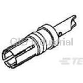
Contact SKT Solder ST Cable Mount 8AWG Bag 0-1393589-7
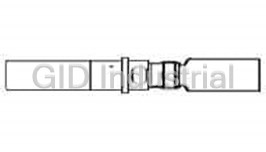
Contact SKT Solder ST Cable Mount 023589-000
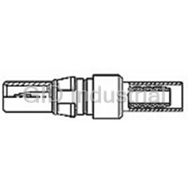
Contact PIN Solder ST Cable Mount Loose 100080-2
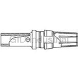
Contact SKT Solder ST Cable Mount 8AWG Loose 100081-1
Contact SKT Solder ST Cable Mount Loose 100082-1
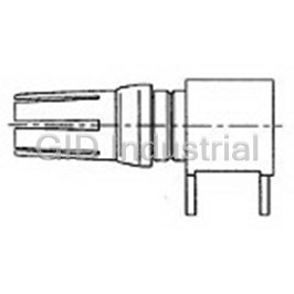
Contact SKT Solder RA Thru-Hole 100092-1
Request a Quote

The quote request has been received
Close

Facing challenges or have inquiries? Feel free to contact us!
Call Us +1-469-283-2440
What they say about us
FANTASTIC RESOURCE
One of our top priorities is maintaining our business with precision, and we are constantly looking for affiliates that can help us achieve our goal. With the aid of GID Industrial, our obsolete product management has never been more efficient. They have been a great resource to our company, and have quickly become a go-to supplier on our list!
Bucher Emhart Glass
EXCELLENT SERVICE
With our strict fundamentals and high expectations, we were surprised when we came across GID Industrial and their competitive pricing. When we approached them with our issue, they were incredibly confident in being able to provide us with a seamless solution at the best price for us. GID Industrial quickly understood our needs and provided us with excellent service, as well as fully tested product to ensure what we received would be the right fit for our company.
Fuji
HARD TO FIND A BETTER PROVIDER
Our company provides services to aid in the manufacture of technological products, such as semiconductors and flat panel displays, and often searching for distributors of obsolete product we require can waste time and money. Finding GID Industrial proved to be a great asset to our company, with cost effective solutions and superior knowledge on all of their materials, it’d be hard to find a better provider of obsolete or hard to find products.
Applied Materials
CONSISTENTLY DELIVERS QUALITY SOLUTIONS
Over the years, the equipment used in our company becomes discontinued, but they’re still of great use to us and our customers. Once these products are no longer available through the manufacturer, finding a reliable, quick supplier is a necessity, and luckily for us, GID Industrial has provided the most trustworthy, quality solutions to our obsolete component needs.
Nidec Vamco
TERRIFIC RESOURCE
This company has been a terrific help to us (I work for Trican Well Service) in sourcing the Micron Ram Memory we needed for our Siemens computers. Great service! And great pricing! I know when the product is shipping and when it will arrive, all the way through the ordering process.
Trican Well Service
GO TO SOURCE
When I can't find an obsolete part, I first call GID and they'll come up with my parts every time. Great customer service and follow up as well. Scott emails me from time to time to touch base and see if we're having trouble finding something.....which is often with our 25 yr old equipment.
ConAgra Foods