


 Manufacturers
TE CONNECTIVITY 1766282-1

Description
Contact Pin Crimp Barrel
1766282-1
Part Number
1766282-1
Price
Request Quote
Manufacturer
TE CONNECTIVITY
Lead Time
Request Quote
Category
Connectors » Connector Contact
Specifications
Manufacturer
TE Connectivity
Manufacturers Part #
1766282-1
Industry Aliases
1766282-1
Sub-Category
Connector Contacts
Brand
AMP
Factory Pack Quantity
500
Datasheet

DDEController?Action=srchrtrv&DocNm=114-13206&DocType=Specification+Or+Standard&DocLang=English&DocFormat=pdf&PartCntxt=1766282-1.pdf
939 KiB

Extracted Text
Application Specification 114-13206 ELCON* Drawer Series Connectors 19 JUL 13 Rev E NOTE NOTE All numerical values are in metric units [with U.S. customary units in brackets]. Dimensions are in millimeters [and inches]. i Unless otherwise specified, dimensions have a tolerance of ±0.13 [±.005] and angles have a tolerance of ±2°. Figures and illustrations are for identification only and are not drawn to scale. 1. INTRODUCTION This specification covers the requirements for application of ELCON Drawer Series Connectors: True Hot Plug, Blind Mating Mixed Signal and Power Connectors. These connectors are designed for use in pluggable wire-to- board applications of power supplies. The connectors are available in a variety of custom configurations. The pin side connector accepts pin contacts, and the socket side connector accepts socket contacts. The contact cavities on both sides of the connector are marked for circuit identification. The high power connectors are available with or without pre-installed guide pins; mid and low power connectors are designed with molded-in guide posts to ensure positive mating of connectors. The molded-in pin protectors prevent damage to the contacts. These features (including the guide pin holes and guide post cavities) have chamfered edges for ease of mating. The connectors are designed for float-mount and fixed-mount applications to allow blind mating with misalignment. All connectors are also designed with standoffs to allow easy printed circuit (pc) board cleaning after soldering. The contacts accept wire sizes 24 through 1/0 AWG. Contact sizes 20, 16, and 12 are available in crimp type, and solder type terminations. In addition, contact size 12 is available in hot plug, specifically designed for current interruption capability. Contact size 0 and 4 is available in crimp type termination, internal thread and external thread for ring lug mounting and bus bar mounting. Pin contacts (except size 0 and 4) are available in three lengths: standard, pre mate, and post mate for flexibility in contact sequencing. The contacts contain an active element, or crown band, which ensures maximum surface contact area, allows even insertion and withdrawal forces, and provides shock and vibration resistance. The contacts are available in loose piece only. Only crimp type and threaded contacts are removable. When corresponding with TE Connectivity Personnel, use the terminology provided in this specification to facilitate your inquiries for information. Basic terms and features of this product are provided in Figure 1. Top Drawer 75 Amp Middle Drawer Socket Side Pin Side Pin Side Socket Side Chamfered Edge Chamfered Edge Mounting Flange Contact Cavities Pin Protector Standoffs Guide Pin Hole Guide Post Guide Post Cavity Guide Pin Figure 1 (Cont’d) ©2013 Tyco Electronics Corporation, a TE Connectivity Ltd. company TOOLING ASSISTANCE CENTER 1-800-722-1111 This controlled document is subject to change. 1 of 17 All Rights Reserved PRODUCT INFORMATION 1-800-522-6752 For latest revision and Regional Customer Service, *Trademark visit our website at www.te.com TE Connectivity, TE connectivity (logo), and TE (logo) are trademarks. Other logos, product and/or company names may be trademarks of their respective owners. 114-13206 Lower Drawer Mini Drawer Chamfered Edge Pin Side Socket Side Pin Side Socket Side Mounting Flange Contact Cavities Pin Protector Standoffs Guide Post Cavity Guide Post Chamfered Edge Dual Power Quad Power Pin Side Socket Side Pin Side Socket Side Mounting Flange Contact Cavities Pin Protector 125 Amp Middle Drawer Double Drawer Socket Side Pin Side Pin Side Socket Side Mounting Flange Contact Cavities Pin Protector Crimp Type Contact Size 0 Solder Type Contact Contact Crimp Type Internal Thread External Thread Figure 1 (End) 2. REFERENCE MATERIAL 2.1. Revision Summary • Updated document to corporate requirements and added new logo Rev E 2 of 17 114-13206 2.2. Customer Assistance Reference Product Base Part Number 1648578 and Product Code D033 are representative of the ELCON Drawer Series Connectors. Use of these numbers will identify the product line and help you to obtain product and tooling information. Such information can be obtained through a local TE Representative, by visiting our website at www.te.com, or by calling PRODUCT INFORMATION or the TOOLING ASSISTANCE CENTER at the numbers at the bottom of page 1. 2.3. Drawings Customer Drawings for product part numbers are available from the service network. If there is a conflict between the information contained in the Customer Drawings and this specification or with any other technical documentation supplied by TE, call Product Information at the number at the bottom of page 1. 2.4. Specifications Product Specification 108-2285 provides product performance and test information. Workmanship Specification 101-654 is a guide for evaluating installed connectors for conditions which effect the cosmetics and/or function of the connector. 2.5. Manuals Manual 402-40 is available upon request and can be used as a guide in soldering. This manual provides information on various flux types and characteristics along with commercial designations and flux removal procedures. A checklist is included in the manual as a guide for information on soldering problems. 2.6. Instructional Material Instruction sheets (408-series) contain detailed assembly instructions and repair procedures for product and tooling. Documents available which pertain to this product are: Document Number Document Title 408-7526 Screw Machine Contacts and Application Tooling 408-10159 Insertion/Extraction Tools for ELCON Circular Contacts 3. REQUIREMENTS 3.1. Material Crimp type contacts are made of copper alloy plated with silver or gold. Solder type contacts are made of brass or copper alloy plated with silver or gold. The crown band is made of copper alloy plated with gold over nickel. Hot plug contacts are made of copper alloy plated with gold. Connector housings are made of polyester, 30% glass filled, UL94-V0. 3.2. Storage A. Ultraviolet Light Prolonged exposure to ultraviolet light may deteriorate the chemical composition used in the connector material. B. Shelf Life The connectors should remain in the shipping containers until ready for use to prevent deformation to the contacts. The connectors should be used on a first in, first out basis to avoid storage contamination that could adversely affect signal transmissions. The shelf life is six months from date of shipment. NOTE NOTE i Silver-plated contacts are shipped in silver-saver packaging to prevent tarnishing until opened. 3.3. Chemical Exposure Do not store connectors near any chemical listed below as they may cause stress corrosion cracking in the contacts. Alkalies Ammonia Citrates Phosphates Citrates Sulfur Compounds Amines Carbonates Nitrites Sulfur Nitrites Tartrates Rev E 3 of 17 114-13206 3.4. Special Features The length of the pin contacts (except size 0 and 4), designated by standard, pre-mate, and post-mate, varies among contact sizes and applies to the portion of the contact that protrudes from the connector after insertion (socket length does not include depth of the connector standoff). Mating socket contacts accept all pin lengths of the same contact size. The length of pin and socket contacts, as described, are shown in Figure 2. Pin Contact Socket Contact “A” “A” Connector Connector CONTACT LENGTH (DIMENSION “A”) PIN CONTACT SIZE SOLDER TYPE PROBE PROOF CRIMP TYPE AND SOLDER TYPE CONTACT (STANDARD) PRE-MATE POST-MATE 20 8.12 [.320] 11.93 [.470] 6.85 [.270] 4.06 [.160] 16 8.38 [.330] 12.19 [.480] 7.36 [.290] 4.06 [.160] 12• 10.92 [.430] 11.68 [.460] 9.90 [.390] 5.33 [.210] 8 10.92 [.430] 12.19 [.480] --- 6.85 [.270] 4 12.95 [.510] --- --- --- 10.92 [.430] Probe Proof Probe Proof 0 --- --- 12.57 [.495] --- •Includes hot plug contacts Figure 2 Probe-proof socket contacts size 0 are designed with a protective cap to provide additional probe-proof protection along with the crown band. This cap must not be removed from the contact. See Figure 3. Some crimp type contacts feature a sight hole located on the side of the wire barrel or in the center of the inside of the wire barrel. See Figure 3. Crimp contacts are rear-insertable and removable. PC board tail are rear- insertable and non-removable. The connector contact cavities contain retention clips. The retention clip is an important feature in holding the crimped contact in the connector. When the contact is fully inserted, the retention clips engage the shoulder of the contact and prevent backing out during mating of the connector. Typical Socket Typical Probe-Proof Crimp Type Pin Contact Contact Size 0 Socket Contact Size 0 with Sight Hole Protective Sight Hole Cap Crown Band Figure 3 3.5. Wire Selection and Preparation The contacts will accept stranded wire sizes 24 through 1/0 AWG. Proper strip length is necessary to properly insert the wire into the contact. The strip length of the wire is shown in Figure 4. CAUTION Reasonable care must be taken not to nick, scrape, or cut any strands during the stripping operation. ! Rev E 4 of 17 114-13206 WIRE SIZE WIRE STRIP WIRE SIZE NOTE: Not to Scale CONTACT RANGE LENGTH 2 SIZE RANGE (mm ) (AWG) ±0.51 [.020] 20 24-20 0.241-0.616 5.33 [.210] 16 18-16 0.963-1.23 6.86 [.270] Wire Strip Length 12 14-12 1.94-2.98 6.86 [.270] 8 10-8• 4.74-8.61 12.7 [.500] 4 6-4• 21.60 12.7 [.500] •Refer to MS 3348, “Contact Bushing, Electrical, Wire Barrel” 0 1/0 53.00 15.2 [.600] Figure 4 3.6. Crimp Type Contacts Crimp contact to wire according to instructions packaged with applicable tooling. These requirements apply equally to the pin contact and the socket contact. A. Wire Barrel Crimp The crimp applied to the wire barrel portion of the contact is the most compressed area and is most critical in ensuring optimum electrical and mechanical performance of the crimped contact. The wire insulation must not enter the contact wire barrel. The crimp height is controlled by proper use of MIL-DTL-22520 crimp tooling. Refer to Section 5, TOOLING for tooling information. CAUTION Reasonable care must be taken not to cut or break the wire insulation during the crimping operation. ! B. Tensile Strength Crimped splices must hold the wire firmly and have a crimp pull-out test value meeting that specified in Figure 5 (the test value is that of the smallest wire size used in the contact). NOTE NOTE i Adjust tensile testing machine for head travel of 25.4 mm [1.0 in.] per minute. Directly and gradually apply force for one minute. Crimped Wire Barrel Wire Conductor Location (Visible in Sight Hole) (Ref) Sight Hole (Ref) WIRE SIZE TENSILE STRENGTH WITH SILVER PLATED WIRE BARREL EFFECTIVE TOOL SELECTOR (AWG) COPPER WIRE (N [lbs]) CRIMP LENGTH (Max) 20 89 [20] 4 16 222 [50] 6 3.30 [.130] 12 489 [110] 8 8 979 [220] 4 1779 [400] --- 5.33 [.210] 1/0 3114 [700] Figure 5 Rev E 5 of 17 114-13206 NOTE NOTE Each crimp dimension represents the functional range of wire and contact combination. The developed crimp configuration is i unique for each tool design and is acceptable provided the crimp height is within the functional range. For crimp dimensions relating to a specific tool, refer to the instruction sheet packaged with manual tools and the applicator log packaged with power tools. C. Conductor Location After crimping, the conductor ends must be flush to the end of the wire barrel. In contacts having a sight hole, this can be verified by checking that the conductor ends are visible in the sight hole. See Figure 5. D. Effective Crimp Length The effective crimp length is the area where the crimp pressure is applied over the length of the wire barrel. E. Straightness After crimping the wire to the contact, the contact must be chucked, and rotated a minimum of 360°. The point of TIR (total indicator reading) measurement must not exceed the dimensions shown in Figure 6. WIRE SIZE RANGE TIR MEASUREMENT Chucking Area Dial Indicator Probe Placed Here (AWG) (Max) for Measurement of TIR 20 0.279 [.011] 28-12 0.305 [.012] 10-4 Wire 0.762 [.030] 1/0 Figure 6 3.7. Threaded Contacts and Guide Posts and Threaded Contacts • Threaded guide posts should not exceed a torque limit of 1.7 Nm [15 in.-lb] • Threaded contacts with M6 threading should not exceed a torque limit of 4.5 Nm [40 in.-lb] • Threaded contacts with 1/4-20 threading should not exceed a torque limit of 6.8 Nm [60 in.-lb] • Threaded contacts with M5 threading should not exceed a torque limit of 2.9 Nm [26 in-lb] 3.8. Connector Spacing Care must be taken to avoid interference between adjacent connectors and/or other components. There is no required spacing between connectors, however spacing may be dependent on variable hardware used and the clearance required for mating connectors. 3.9. Panel Cutout The pin side connector and socket side connector can be installed or removed from either the back or the front of the panel (front of the panel is recommended). Usually, the socket side connector is mounted in the cabinet (energized) panel, while the pin side connector is mounted in the drawer (passive) panel. Dimensions for mounting holes, guide pins (if applicable), and panel cutouts, and maximum panel thickness for rear mounting are shown in Figure 7. 3.10. Contact Insertion and Extraction Normally an insertion tool is not required to insert contacts into connectors, but if the wire bundle is large or individual wires are fragile, using an insertion tool is recommended. Push contact straight into the contact cavity until it bottoms (an audible click). After inserting contact into connector, pull back lightly on the wire to ensure contact is fully seated. The contacts are rear-insertable and rear-releasable; an extraction tool is needed to disengage the connector retention clips and remove the contact from the back of the connector. Only crimp type and threaded contacts are removable. Refer to Section 5 for tooling information. 3.11. PC Board Connectors A. PC Board Material and Thickness The pc board material shall be glass epoxy (FR-4 or G-10). The pc board thickness range shall be 1.38 through 5.08 mm [.054 through .200 in.]. Rev E 6 of 17 114-13206 NOTE NOTE Contact the Product Information Center at the number listed at the bottom of page 1 for suitability of other board materials and i thicknesses. B. PC Board Tolerance Maximum allowable bow of the pc board shall be 0.03 mm [.001 in.] over the length of the connector. C. Connector Placement The connector number one position must be aligned with the number one position board hole. When placing connectors on the pc board, make sure that the contact solder tails are aligned and started into the matching holes before seating the connector onto the pc board. CAUTION Connectors should be handled only by the housing to avoid deformation, contamination, or damage to the contact solder tails. ! Recommended Panel Cutout 6.35 mm [.250 in.] Mounting Hole Dia (4 Places) A B D Threaded Hole for Applicable Shoulder Screw (2 Places) E C Panel Thickness: 4.76 mm [.188 in.] (Max) CONNECTOR ABCD E QUADPOWER 53.98 [2.125] 43.18 [1.700] 43.18 [1.700] 50.80 [2.000] 24.89 [.980] DUALPOWER 35.56 [1.400] 25.40 [1.000] 43.18 [1.700] 33.02 [1.300] 24.89 [.980] TOP DRAWER, DOUBLE DRAWER 98.29 [3.870] 88.90 [3.500] 43.18 [1.700] 95.25 [3.750] 24.89 [.980] 125A MIDDLE DRAWER 72.01 [2.835] 62.99 [2.480] 35.56 [1.400] --- --- 75A MIDDLE DRAWER 76.20 [3.000] 67.31 [2.650] 36.83 [1.450] --- --- LOWER DRAWER 76.20 [3.000] 66.67 [2.625] 25.40 [1.000] --- --- MINI DRAWER 69.75 [2.746] 58.55 [2.305] 23.62 [.930] --- --- Figure 7 CAUTION For applications using panel mounted threaded fasteners, care must be taken that the threaded hole does not compromise the ! shoulder area of the shoulder screw used to fasten the float mount connector. Rev E 7 of 17 114-13206 D. PC Board Layout The mounting holes and contact holes in the pc board must be precisely located to ensure proper placement and optimum performance of the connector. Design the pc board using the dimensions provided in Figure 8. Figure 8 (Cont’d) Rev E 8 of 17 114-13206 Figure 8 (Cont’d) Rev E 9 of 17 114-13206 Figure 8 (Cont’d) Rev E 10 of 17 114-13206 Figure 8 (End) Rev E 11 of 17 114-13206 E. PC Board Hole Dimensions The solder type contacts may be used with or without plated through holes. If plated, the drilled hole size, plating types, and plating thickness are dependent on the application requirements. The finished hole size must be as stated to provide unrestricted insertion and ensure adequate application of solder to the solder tines. See Figure 9. Trace Width (As Required) Pad Width (As Required) Plating Recommendations: Drilled Hole Diameter Tin Plate 0.005 mm [.0002 in.] Min. Thick (As Required) Over Copper 0.025 mm [.0010 in.] Thick Copper Plating (Ref) (Max Hardness 150 Knoop) Finished Hole Diameter After Plating (Refer to Table) Tin-Lead Plating (Ref) CONTACT SIZE FINISHED HOLE DIAMETER (+0.08 [+.003]) 20 1.20 [.047] 16 1.80 [.070] 12• 2.65 [.104] 8 3.82 [.152] •Includes hot plug contacts Figure 9 3.12. Connector Seating The connector standoffs must be seated on the pc board or panel not exceeding the dimension shown in Figure 10. NOTE NOTE i Hold-downs may be used to ensure stability during the soldering procedure. 0.51 0.51 [.020] [.020] PC Board (Ref) Connector Standoffs Wire Figure 10 3.13. Soldering Observe guidelines and procedures when soldering contacts is required. All solder joints should conform to those specified in Workmanship Specification IPC-A-610 and all other requirements specified in this document. Contacts must be stabilized during soldering with a non-metallic material. Solder, clean, and dry all wire leads to contacts according to the following: Rev E 12 of 17 114-13206 A. Flux Selection Wire lead and contact wire barrel interior shall be fluxed prior to soldering using a mildly active rosin. Flux must be compatible with manufacturing, safety, and health guidelines. B. Cleaning After cleaning, removal of fluxes, residues, and activators is mandatory. Cleaning procedures and solvents depend on the type of flux used. See Figure 11. DANGER Consideration must be given to toxicity and other safety and health requirements as recommended in the Material Safety Data ! Sheet supplied by the solder cleaning solvent manufacturer. CLEANER TIME TEMPERATURE (Minutes) (Maximum) NAME TYPE ALPHA 2110 Aqueous 1 132°C [270°F] BIOACT EC-7 Solvent 5 100°C [212°F] Butyl CARBITOL Solvent 1 Ambient Room Isopropyl Alcohol Solvent KESTER 5778 Aqueous KESTER 5779 Aqueous 5 100°C [212°F] LONCOTERGE 520 Aqueous LONCOTERGE 530 Aqueous Terpene Solvent Figure 11 C. Drying When drying cleaned connector assemblies, make certain that the recommended temperature limitations of -40 to +105°C [-40 to +221°F] are not exceeded. Excessive temperatures may cause housing degradation. 3.14. Connector Loading These connectors provide optimum mapping of pin to function, and ease of routing in the system by accepting various contact sizes, quantities, and types. All connector contact positions accept crimp type and solder type terminations. In addition, high power connectors accept threaded contacts (size 0 only). Possible contact options for loading individual connectors are shown in Figure 12. CONTACTS CONNECTOR CONNECTOR RATING 04 8 12 16 20 DOUBLE DRAWER 4 --- --- 11 --- 24 150A/200A† TOP DRAWER 2 --- --- 6 12 32 150A/200A† 125A MIDDLE DRAWER --- 2 --- 6 --- 32 125A 75A MIDDLE DRAWER --- --- 4 9 --- 24 75A --- --- --- 8 --- 21 LOWER DRAWER‡ --- --- --- 4 4 21 35A --- --- --- --- 8 21 --- --- --- 6 --- 16 MINI DRAWER• --- --- --- 3 3 16 35A --- --- --- --- 6 16 DUALPOWER 2 --- --- --- --- --- 150A/200A† QUADPOWER 4 --- --- --- --- --- 150A/200A† †200A when mounted on bus bar. ‡Three Lower Drawer housing variations with different combinations of contact size 12 and 16 are available. •Three Mini Drawer housing variations with different combinations of contact size 12 and 16 are available. Figure 12 ALPHA, BIOACT, CARBITOL, LONCOTERGE, and KESTER are trademarks of their respective owners. Rev E 13 of 17 114-13206 3.15. Mounting Hardware The connectors can be float mounted or fixed mounted to a backplane or chassis. The float mount shoulder screws are designed to secure a connector to a panel. The panel must flex and be of sufficient gauge to support mating loads. These screws allow some movement of the assembly for easier mating. Connectors can be fixed mounted using commercially available screws with a head that will not interfere with connector mating. Washers can also be used to make up the difference for the required hardware diameter. High power connectors are fixed mounted using the mounting flange or, if available, the guide pins (which have internal 6-32 threads). Hardware for specific connector types is shown in Figure 13. NOTE NOTE i PC board connectors must be fixed mounted. Float Mounting Mounting Flange Float Mount Shoulder Screw 10-32 or M5 Top Drawer and Double Drawer Panel (Ref) 6-32, 8-32 or M4 Mini Drawer, Lower Drawer, and 75A/125A Middle Drawer Fixed Mounting Optional Fixed Mounting for High Power Connectors Only Internally Threaded (6-32) Guide Pin Commercially Available Screw and Washer‡ Commercially Available Screw and Washer‡ ‡Hardware Diameter 9.52 mm [.375 in.] Top Drawer, Double Drawer 12.7 mm [.500 in.] 75A, 125A Middle Drawer, Lower Drawer and Mini Drawer Figure 13 Rev E 14 of 17 114-13206 3.16. Connector Mating and Alignment The pre-installed guide pins and molded-in guide posts ensure positive mating of connectors. In addition, because of their symmetrical design, the low power connectors have a polarizing feature: a rib in the guide post cavity that fits into a notch in the guide post. When fully engaged, the dimension between the pin side connector and socket side connector must be within the limit provided to ensure full mating. See Figure 14. When mounted, the float mount design allows blind mating with gatherability up to 2.54 mm [.100 in.]. “A” Low Power Connectors Polarizing Feature Rib in Guide Post Cavity MATING DIMENSION CONNECTOR “A” (MAX) Notch in Guide Post Double Drawer, Top Drawer, 75A and 125A Middle Drawer, 12.70 mm [.500 in] Mini Drawer Lower Drawer 10.16 mm [.400 in.] Figure 14 3.17. Special Assembly Consideration The system into which the connectors are installed must support the weight of the drawer when connectors are engaged (for example, the drawer must bottom on a built-in stop, not on the connector). 3.18. Strain Relief and Wire Dress If required, wires can be bundled together and supported with cable ties. Wires must not be stretched or confined in any way that would restrict the floating action of the connectors. Therefore, the wires must remain perpendicular to the connector and avoid an excessively sharp bend radius. The minimum distance for the cable tie, measured from the wire end of the connector to the cable tie, and the minimum bend radius of a wire bundle is shown in Figure 15. 152.4 [6.0] (Min) 10 Times Diameter Connector of Largest Cable Cable Tie Figure 15 Rev E 15 of 17 114-13206 3.19. Repair Damaged connectors must be removed, discarded, and replaced. Connectors with solder type contacts will require desoldering of all contact solder tails. Solder type contacts are not removable from the housing assembly. Damaged crimp type contacts must be removed from the connector, discarded, and replaced with new ones. CAUTION Damaged product should not be used. If a damaged contact is evident before the contact is inserted into the housing, cut the ! wire in back of the contact and re-terminate the wire end. If contact is damaged after insertion, remove the contact with the extraction tool and cut the wire in back of the contact and re-terminate wire end. 4. QUALIFICATIONS ELCON Drawer Series Connectors and Contacts are Recognized by Underwriters Laboratories Inc. (UL)/CSA International in File E28476. 5. TOOLING Hand and pneumatic crimping tools that accommodate the full wire size range are designed for terminating crimp type contacts. The insertion/extraction tools are designed to insert and remove crimp type and threaded contacts from connectors. The tool depresses the connector internal retention clips without deforming them. Tooling part numbers and instructional material packaged with the tooling are shown in Figure 16. NOTE NOTE i Military standard Daniels bench mount crimping machine is applicable for terminating crimp type contacts. This machine has been designed to form indents to the proper depth in the contact wire barrel. It requires a specially designed funnel which helps gather wire strands and guide them into the closed barrel of the contacts. It is designed for production requirements. Refer to Figure 16. For Wire Sizes 12-24 AWG Hand Crimping Tool 601967-1 with Turret Head 601967-2 (408-7516) Insertion/Extraction Tool (Typ) (408-10159) For Wire Sizes 1/0 and 8 AWG Daniels Heavy Duty Pneumatic Bench Machine M22520/23-01 with: TOOL CONTACT Wire Size 8 AWG INSERTION EXTRACTION SIZE Daniels Indentor Head M22520/23-02 PN TIP COLOR TIP COLOR Daniels Locator M22520/23-09 1643914-1 --- Red 8 Wire Size 1/0 AWG 1643915-1 Yellow White 12 Daniels Indentor Head M22520/23-05 1643916-1 Blue White 16 Daniels Locator M22520/23-13 1643917-1 Red White 20 Wire Size 4 AWG 1643921-1 --- Yellow 0 Daniels Indentor Head M22520/23-04 Daniels Locator M22520/23-11 1643922-1 --- Blue 4 Figure 16 Rev E 16 of 17 114-13206 6. VISUAL AID The illustration below shows a typical application of this product. This illustration should be used by production personnel to ensure a correctly applied product. Applications which DO NOT appear correct should be inspected using the information in the preceding pages of this specification and in the instructional material shipped with the product or tooling. FIXED MOUNTING SOLDER MUST BE EVENLY SCREWS MUST BE FORMED AROUND ALL SECURE CONTACT TAILS CRIMP MUST BE CENTERED ON CONTACT WIRE WIRE CONDUCTOR BARREL ENDS MUST BE VISIBLE IN CONTACT SIGHT HOLE WIRE INSULATION FLOAT MOUNTING MUST NOT ENTER SCREWS MUST CONTACT WIRE ALLOW MOVEMENT BARREL OF CONNECTOR WIRE INSULATION AND CONDUCTORS MUST BE UNDAMAGED CONNECTOR MUST BE SEATED ON PC BOARD CONNECTOR MUST BE SEATED ON PANEL CONTACTS MUST BE LOCKED IN PLACE FIGURE 17. VISUAL AID Rev E 17 of 17
Frequently asked questions
How does Electronics Finder differ from its competitors?

Is there a warranty for the 1766282-1?
Which carrier will Electronics Finder use to ship my parts?
Can I buy parts from Electronics Finder if I am outside the USA?
Which payment methods does Electronics Finder accept?
Why buy from GID?

Quality
We are industry veterans who take pride in our work

Protection
Avoid the dangers of risky trading in the gray market

Access
Our network of suppliers is ready and at your disposal

Savings
Maintain legacy systems to prevent costly downtime

Speed
Time is of the essence, and we are respectful of yours
Related Products
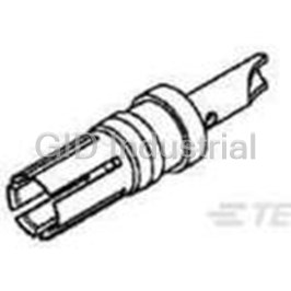
Contact SKT Solder ST Cable Mount 8AWG Bag 0-1393589-7
Contact SKT Solder ST Cable Mount 023589-000
Contact PIN Solder ST Cable Mount Loose 100080-2
Contact SKT Solder ST Cable Mount 8AWG Loose 100081-1
Contact SKT Solder ST Cable Mount Loose 100082-1
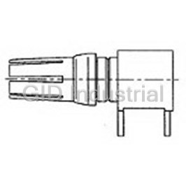
Contact SKT Solder RA Thru-Hole 100092-1


Request a Quote

The quote request has been received

Close

Facing challenges or have inquiries? Feel free to contact us!
Call Us +1-469-283-2440
What they say about us
FANTASTIC RESOURCE
One of our top priorities is maintaining our business with precision, and we are constantly looking for affiliates that can help us achieve our goal. With the aid of GID Industrial, our obsolete product management has never been more efficient. They have been a great resource to our company, and have quickly become a go-to supplier on our list!
Bucher Emhart Glass
EXCELLENT SERVICE
With our strict fundamentals and high expectations, we were surprised when we came across GID Industrial and their competitive pricing. When we approached them with our issue, they were incredibly confident in being able to provide us with a seamless solution at the best price for us. GID Industrial quickly understood our needs and provided us with excellent service, as well as fully tested product to ensure what we received would be the right fit for our company.
Fuji
HARD TO FIND A BETTER PROVIDER
Our company provides services to aid in the manufacture of technological products, such as semiconductors and flat panel displays, and often searching for distributors of obsolete product we require can waste time and money. Finding GID Industrial proved to be a great asset to our company, with cost effective solutions and superior knowledge on all of their materials, it’d be hard to find a better provider of obsolete or hard to find products.
Applied Materials
CONSISTENTLY DELIVERS QUALITY SOLUTIONS
Over the years, the equipment used in our company becomes discontinued, but they’re still of great use to us and our customers. Once these products are no longer available through the manufacturer, finding a reliable, quick supplier is a necessity, and luckily for us, GID Industrial has provided the most trustworthy, quality solutions to our obsolete component needs.
Nidec Vamco
TERRIFIC RESOURCE
This company has been a terrific help to us (I work for Trican Well Service) in sourcing the Micron Ram Memory we needed for our Siemens computers. Great service! And great pricing! I know when the product is shipping and when it will arrive, all the way through the ordering process.
Trican Well Service
GO TO SOURCE
When I can't find an obsolete part, I first call GID and they'll come up with my parts every time. Great customer service and follow up as well. Scott emails me from time to time to touch base and see if we're having trouble finding something.....which is often with our 25 yr old equipment.
ConAgra Foods