


 Manufacturers
TE CONNECTIVITY 47237-1

Description
Contact SKT Crimp ST Cable Mount
47237-1
Part Number
47237-1
Price
Request Quote
Manufacturer
TE CONNECTIVITY
Lead Time
Request Quote
Category
Connectors » Connector Contact
Specifications
Manufacturer
TE Connectivity
Manufacturers Part #
47237-1
Industry Aliases
47237-1
Sub-Category
Connector Contacts
Brand
AMP
Factory Pack Quantity
1
Datasheet

DDEController?Action=showdoc&DocId=Specification+Or+Standard%7F408-1724%7FN%7Fpdf%7FEnglish%7FENG_SS_408-1724_N.pdf
355 KiB

Extracted Text
37869(8.43-**8 /)+.),’)%01(/-2’( &-/",$ %/+),"*0"*: 41464)*48 "41464)*48 ! "4 $%*)*)48 $%19*19*48 $%*114;#*114;#48 $%*)*)48 Figure 1 2. Remove latch pin on head, then open yoke. See Figure 2. This instruction sheet provides information on product application and a maintenance and inspection 3. Loosen set screw in yoke. procedure for the crimping dies listed in Figure 1. The dies are used in Hydraulic Crimping Heads 58422–1, 4. Insert stationary die into well of yoke as shown 69066, 1752877–1, and 1752787–1. For detailed in Figure 2. Tighten set screw. information on the hydraulic power unit and hydraulic crimping head, refer to the instructions packaged with 5. Activate power unit to advance ram until set these tools. screw is visible. These dies are designed to crimp AMPLI–BOND and PLASTI–GRIP terminals on wire sizes 8 AWG to40*#*87(6*; &8(-.3*24:*) 2 AWG. Dies are coated with a preservative to prevent rust and corrosion. Wipe preservative from 8&8.43&6< dies, particularly from crimping areas. .* 4:.3,.* " Reasons for reissue are provided in Section 6, REVISION SUMMARY. "! 8451&8* " " &2 )%,01"**"1)-,*87(6*; 1. Refer to the chart in Figure 1 and verify that you have the proper die set for the terminal and wire Figure 2 size being used. -.7(4386411*))4(92*38.779’/*(884(-&3,*1*(8643.(746546&8.43&66.7’96,4+ 1138*63&8.43&1.,-87*7*6:*)! 461&8*786*:.7.43&3)*,.43&197842*6*6:.(* 14,4&3)<(4 1*(8643.(7&6*86&)*2&607:.7.8496;*’7.8*&815#-%*%#1/-,)#0#-+333 8-*6564)9(8714,47&3)(425&3<3&2*797*)&6*8-*5645*68<4+8-*.66*75*(8.:*4;3*67 6&)*2&60 <(4 0),/)-’)&12(0.3’( 6. Loosen set screw in ram and insert moving die *..*(*# into ram well as shown in Figure 2. Tighten set ",(&)’*)$/" screw. "-..&*),2&" ! ! 7. Activate power unit to allow ram to return to the “down” position. )&&,.4#+ ..&*),2&" 1. Remove latch pin and open yoke. *0&)$&" 2. Loosen set screw in yoke and remove stationary die. 3. Raise ram to “full up” position. Loosen set screw and remove moving die. ",(&)’&,",,"’ "-.-$&)-. .*+’." 20)//)-’#-%0),/)-’0.$&%30& Figure 4 ! 3. With yoke open, place terminal on dies. See Figure 4.! 4. Bottom of terminal tongue should face stationary die and terminal wire barrel should rest against 1. Strip wire to dimensions listed in Figure 3. Do stop plate as shown in Figure 4. NOT nick or cut conductor strands. 5. Close yoke and insert latch pin. 2. Insert stripped wire in terminal. End of wire must be flush with or extend beyond edge of terminal! wire barrel.!! 6. Hold terminal in place and activate power unit to complete crimp. Open yoke and remove crimped terminal. &,".,&+ ")$.%2+! -13+#2).-0),/%*312,&-2 &,"/-."’/-%*,1.")! This adjustment is made to both stationary and "2*)!!$"*#&,",,"’ moving dies after they have been placed in crimping head. "1. The dies have three insulation crimp positions. The adjustment is made by moving a pin–key (see !! Figure 5). When the pin–key is pushed all the way in, the insulation crimping section of the die is in the loose position; when the pin–key is halfway out, the insulation crimping section of the die is in the medium position; when the pin–key is all the way out, the insulation crimping section of the die Figure 3 is in the tight position. *#2 *’" .,*)& -*,+*,.&*)"0 )0& 2. To adjust the insulation crimp, loosen socket 3. Press and hold insulation die down against the head cap screws and push pin–key all the way in pin–key. This will prevent the spring–loaded so that insulation crimp section of the die is in the pin–key from popping back. loose position. 4. Tighten socket head cap screws. 2!2).-!07 .+.0.$%"$#%$ "!#$ # )% &#$$ "(#" $%#$$ $#! #$ )-%7 5. Perform a test crimp (refer to Paragraph 3.1). $"#!" &)"! ’" #%$ $"#!" & ( .#*%2%!$ )0%!00%+)#%!! "$ "$’" !/#0%51-13+!2).-!00%+0),/)-’%#2).- 0),/)-’%#2).- 6. Remove crimped terminal from dies and visually inspect the insulation crimp portion of terminal. The insulation crimp should “grip” wire insulation (when using AMPLI–BOND terminals) or provide.#*%2%!$ “support” for wire insulation (when using!/#0%51 .4)-’PLASTI–GRIP terminals). )% 7. If the insulation crimp does not grip or support wire insulation as described in step 6, loosen )-%7 socket head cap screws and set the pin–keys in -13+!2).-!00%+ the medium position. Then follow Steps 3 and 4. 0),/)-’%#2).- .+.0.$% 8. Make another test crimp over previously Figure 5 crimped terminal. )0%-.2&3++7)-1%02%$ )0%&3++7)-1%02%$ 0),/-.2#%-2%0%$.-5)0%"!00%+%0,)-!+5!1-.2"322%$ !’!)-1212.//+!2%%%)’30% 0),/#%-2%0%$.-5)0%"!00%+ $)%!-$2%0,)-!+#.+.0#.$%#.,")-!2).-%%)’30% .00%#2#.+.0#.$%!-$$)%#.,")-!2).-%0,)-!+)-13+!2).- #.+.0,!2#(%1#.+.0$.21.-$)%1 6#%11)4%&+!1(.0%6203$%$)-13+!2).-1)8%.0$!,!’%$ $)%1 )0%1)8%"%)-’31%$)11!,%!15)0%1)8%%,".11%$.- 2%0,)-!+)-13+!2).-!-$12!,/%$.-2%0,)-!+2.-’3% -$.&#.-$3#2.0)1-.2&+31(5)2(.0%62%-$)-’"%7.-$%-$.& 5)0%"!00%+.&2%0,)-!+-$.&#.-$3#2.0)1&+31(5)2(.0%62%-$1"%7.-$%-$.& 5)0%"!00%+.&2%0,)-!+ )0%)-13+!2).-/)-#(%$-13+!2).-#0),/2..2)’(2.- 2%0,)-!+1-13+!2).-"!00%+)1)-#.-2!#25)2(5)0%)-13+!2).- 2%0,)-!+1(!4%)-13+!2).-9’0)/!-$ )#*%$.0,)11)-’#.-$3#2.0120!-$1 2%0,)-!+1(!4%)-13+!2).-913//.02 Figure 6 %47#.+%#20.-)#1.0/.0!2).-.& 0.-’ 0.-’ ’!#&!$!() ’%* 9. Remove crimped terminal from dies and visually may gage within permissible limits, worn or damaged inspect insulation crimp. die closure surfaces can affect the quality of the crimp. Examples of possible damaged die surfaces 10. Repeat adjustment as necessary until desired are shown in Figure 7. insulation crimp is obtained. Do NOT use a tighter setting than required. "*$(&)!%$ 11. Refer to Paragraph 3.4 and Figure 6 for crimp Every die set is inspected and tested for proper die inspection procedure. closure dimensions before packaging. An inspection should be performed periodically to check the die %"%’% closure for excessive wear. Terminals and dies are color coded as listed in Figure 1 and shown in Figure 5. The dies have the terminal size stamped in the wire barrel crimp sections of both the moving and stationary dies. When crimped, the wire size will appear on both sides of the terminal wire barrel. The wire size appearing on the crimped wire barrel should always agree with the wire size stamped on the terminal tongue. ’!#&$(&)!%$ Inspect crimped terminals by checking the features described in Figure 6. " ! !$# !" # !"! " ! Figure 7 Use only the terminals that meet the conditions The die closure inspection is accomplished using plug shown in the “ACCEPT” column. “REJECT” terminals gages. A suggested gage design and the GO and can be avoided through careful use of instructions in NO–GO dimensions of the plug gage elements are Paragraphs 3.1 and 3.2, and by performing regular shown in Figures 8 and 9. The following procedure is die maintenance described in Section 4. recommended for inspecting the die closures. 1. Clean oil or dirt from the bottoming surfaces, die closure surfaces, and plug gage elements. Regular inspections should be performed by quality control personnel. A record of scheduled inspections 2. Remove two socket head cap screws and stop should remain with the dies and/or be supplied to the plate from moving die. See Figure 10, Detail A. supervisory personnel responsible for the dies. This will provide access to the wire barrel dies for Though recommendations call for at least one plug gaging. inspection a month, the inspection frequency should be based on the amount of use, ambient working 3. Assemble stationary and moving dies so that wire barrel dies are bottomed, but not under conditions, operator training and skill, and established pressure. See Figure 10. company standards. These inspections should be performed in the following sequence: 4. With wire barrel dies bottomed, inspect the wire "$!$barrel crimp die closure using the proper plug gage. Hold gage in straight alignment with the die Do not allow deposits of dirt, grease, or foreign matter closure and carefully try to insert, without forcing, to accumulate in the die closure area, or on the the GO element. See Figure 10, Detail A. The GO bottoming surfaces of the dies. These deposits may element must pass completely through the wire prevent the dies from bottoming fully and may also barrel crimp die closure. cause excessive wear in the die closure surfaces, thereby affecting the quality of the crimp. The dies 5. Try to insert the NO–GO element. The NO–GO should be wiped clean frequently with a clean cloth. element may enter partially, but must not pass completely through the wire barrel die closure. !(*"$(&)!%$ Visually inspect the die closure surfaces for flattened, 6. Re–install stop plate and secure with the two broken, pitted, or chipped conditions. Although dies socket head cap screws. (#$’#%!# )*"(&+!" !#)’!#)’ !$+& Figure 8 !#$(!%$,!#$(!%$, !#$(!%$,+& !#$(!%$, !$+& , ,, Figure 9 7. Loosen socket head cap screws from both and controlled to prevent lost time when replacement stationary and moving insulation dies and move of parts is necessary. Order replacement parts pin–keys all the way out so that insulation crimping through your Tyco Electronics Representative, or call sections of dies are in the tight position. 1–800–526–5142, or send a facsimile of your See Figure 10, Detail B. purchase order to 1–717–986–7605, or write to: 8. Press and hold insulation die down against CUSTOMER SERVICE (38–35) pin–key, and tighten the socket head cap screws. TYCO ELECTRONICS CORPORATION P.O. BOX 3608 9. With wire barrel dies bottomed, inspect the HARRISBURG, PA 17105–3608 insulation crimp die closure using the proper plug gage in the same manner as steps 3 through 5. Dies may be returned for evaluation and repair. For See Figure 10, Detail B. die repair service, contact a representative at 10. If both wire barrel and insulation die closures 1–800–526–5136. meet the plug gage conditions, the dies are considered to be dimensionally correct. Updated document to corporate requirements The parts listed in Figure 11 are customer– New format replaceable. A complete inventory can be stocked *+%")’%$!(%’&%’)!%$% $ #!%&$"’ )1%!11%,)%2/33/-%$ 43/3.$%11%2241% /#+%3%!$ !0#1%62 !0#1%62!.$ )1%!11%,)%2/33/-%$ 3/0,!3%%-/5%$).%72).)’(3/2)3)/. 43/3.$%11%2241% %,%-%.3-4230!22#/-0,%3%,73(1/4’( 3(%$)%#,/241% %,%-%.3-!7%.3%10!13)!,,7"43-423 ./30!22#/-0,%3%,73(1/4’(3(%$)%#,/241% Figure 10 3!3)/.!17)% #1%6 /5).’)% .2%13.24,!3)/. %722%-",7$*423!",% 01).’ 3/0,!3% 01).’ #1%6 ,%%5% Figure 11 /&7#/,%#31/.)#2/10/1!3)/.%5 !2(%1 !2(%1
Frequently asked questions
How does Electronics Finder differ from its competitors?

Is there a warranty for the 47237-1?
Which carrier will Electronics Finder use to ship my parts?
Can I buy parts from Electronics Finder if I am outside the USA?
Which payment methods does Electronics Finder accept?
Why buy from GID?

Quality
We are industry veterans who take pride in our work

Protection
Avoid the dangers of risky trading in the gray market

Access
Our network of suppliers is ready and at your disposal

Savings
Maintain legacy systems to prevent costly downtime

Speed
Time is of the essence, and we are respectful of yours
Related Products
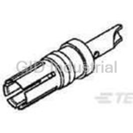
Contact SKT Solder ST Cable Mount 8AWG Bag 0-1393589-7
Contact SKT Solder ST Cable Mount 023589-000
Contact PIN Solder ST Cable Mount Loose 100080-2
Contact SKT Solder ST Cable Mount 8AWG Loose 100081-1
Contact SKT Solder ST Cable Mount Loose 100082-1
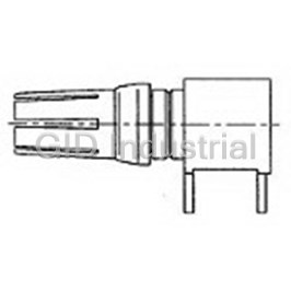
Contact SKT Solder RA Thru-Hole 100092-1


Request a Quote

The quote request has been received

Close

Facing challenges or have inquiries? Feel free to contact us!
Call Us +1-469-283-2440
What they say about us
FANTASTIC RESOURCE
One of our top priorities is maintaining our business with precision, and we are constantly looking for affiliates that can help us achieve our goal. With the aid of GID Industrial, our obsolete product management has never been more efficient. They have been a great resource to our company, and have quickly become a go-to supplier on our list!
Bucher Emhart Glass
EXCELLENT SERVICE
With our strict fundamentals and high expectations, we were surprised when we came across GID Industrial and their competitive pricing. When we approached them with our issue, they were incredibly confident in being able to provide us with a seamless solution at the best price for us. GID Industrial quickly understood our needs and provided us with excellent service, as well as fully tested product to ensure what we received would be the right fit for our company.
Fuji
HARD TO FIND A BETTER PROVIDER
Our company provides services to aid in the manufacture of technological products, such as semiconductors and flat panel displays, and often searching for distributors of obsolete product we require can waste time and money. Finding GID Industrial proved to be a great asset to our company, with cost effective solutions and superior knowledge on all of their materials, it’d be hard to find a better provider of obsolete or hard to find products.
Applied Materials
CONSISTENTLY DELIVERS QUALITY SOLUTIONS
Over the years, the equipment used in our company becomes discontinued, but they’re still of great use to us and our customers. Once these products are no longer available through the manufacturer, finding a reliable, quick supplier is a necessity, and luckily for us, GID Industrial has provided the most trustworthy, quality solutions to our obsolete component needs.
Nidec Vamco
TERRIFIC RESOURCE
This company has been a terrific help to us (I work for Trican Well Service) in sourcing the Micron Ram Memory we needed for our Siemens computers. Great service! And great pricing! I know when the product is shipping and when it will arrive, all the way through the ordering process.
Trican Well Service
GO TO SOURCE
When I can't find an obsolete part, I first call GID and they'll come up with my parts every time. Great customer service and follow up as well. Scott emails me from time to time to touch base and see if we're having trouble finding something.....which is often with our 25 yr old equipment.
ConAgra Foods