

 Manufacturers
THOMAS & BETTS FSA12

Description
Connector Accessories Conduit Adapter Cast Aluminum
FSA12
Part Number
FSA12
Price
Request Quote
Manufacturer
THOMAS & BETTS
Lead Time
Request Quote
Category
Connectors » Connector Accessories
Specifications
Manufacturer
Thomas & Betts
Manufacturers Part #
FSA12
Sub-Category
Connector Accessories
Factory Pack Quantity
1
Datasheet

Extracted Text
Electrical Interconnection Systems for Heavy-Duty Applications ® MaxGard ™ J-Line ® DuraGard ™ FS/FD ® UniGard ® DuraTite ® Ever-Lok Control Circuit Industrial Interlock United States Tel: 901.252.8000 www.tnb.com 800.326.5282 Fax: 800.888.0690 ® Russellstoll Interconnection Systems Stand Up to Your Toughest Environments. When you’re dealing with electrical connections in wet, corrosive or hazardous environments, performance, safety and durability ® ® ® are of paramount importance. Russellstoll MaxGard and DuraGard interconnection systems provide superior waterproof ® connections in rugged, corrosion-resistant, waterproof, UL 94-V0 rated housings. You can rely on Russellstoll plugs, connectors and receptacles to safely provide power where you need it — even under the harshest indoor and outdoor conditions. Heavy Industrial/Marine Washdown and Light Marine Industrial and Commercial Control Circuit and Industrial/ Hazardous Location Applications Applications Applications Interlock Applications Applications At T&B, we’re committed to: Convenience of single-order, single-shipment to your site for thousands of stocking items Expert local point of contact for clear, consistent information regarding training, codes and standards Quality brands that have proven themselves over time Inventive design and manufacture of problem-solving products Offering a best-of-class warranty and returns policy Uniform carton labeling with additional bar-coding for convenient inventory management Nationwide network of stocking electrical distributors Outstanding customer service capability Supplying you with the right products, convenient packaging, on-time delivery and competitive pricing We deliver the solutions that make your job easier and offer the power to bring it all together in one package. Call us today and let us help you profit from sourcing your electrical products from the leader, Thomas & Betts. ® Russellstoll Electrical Interconnection Systems Call 1-800-326-5282 for Immediate, Heavy Industrial/Marine..............................5–66 Knowledgeable Assistance. ® MaxGard Interconnection Systems..........6–53 ™ J-Line Interconnection Systems............54–65 Every Thomas & Betts Customer Service Representative is Washdown Industrial/Light Marine ........67–118 ® right where the action is — DuraGard Waterproof Connections ........68–85 ™ FS/FD Metallic Connections ..................86–98 surrounded by all the support ® UniGard Pin & Sleeve IEC Connections ....99–118 and information they need to answer your questions and Industrial and Commercial....................119–142 ® ® fill your orders faster than DuraTite and Ever-Lok Locking Connections ..........................120–142 ever. Your calls and faxes are automatically routed to Control Circuit and Industrial account specialists who personally serve your region and can answer Interlock Applications ..........................143–162 Control Circuit Connectors....................144–153 in-depth questions about products, provide pricing information and Industrial Interlocked Receptacles ........154–162 process orders accurately and efficiently. Hazardous Locations ............................163–174 For Customer Service and Order Inquiries, call: 1-800-326-5282 or fax 1-800-888-0690. Computer Systems ................................175–185 Index ......................................................186–200 ® T&B Access for Online 24/7 Information at Your Fingertips. T&B Access is an online tool that provides distributors with a “real-time” solution for the most frequent inquiries and order requests. Now distributors can obtain a faster answer without having to make a phone call to T&B. Through T&B Access, you can check order status, price and availability, retrieve an electronic copy of an invoice and packing slip and use our online competitor cross reference. You also take advantage of our Express Order Service, verify delivery service options, arrange for returns and send an automated expedite e-mail directly to your CSR — no phone call required. In a real hurry? Go to www.tnb.com today and discover the advantages T&B Access provides for T&B Distributor partners, day or night. Call 1-800-858-6022 for our toll-free, 24-hour Fax-On-Demand service, technical documentation, brochures and product literature, or visit our website at www.tnb.com. United States United States Canada T Tel: echnical Ser 901.252.8000 vices Tel: 901.252.8000 Tel: 450.347.5318 Tel: 888.862.3289 800.326.5282 1 www.tnb.com Fax: 901.252.1354 Fax: 450.347.1976 Fax: 800.888.0690 Russellstoll Application Guide This catalog has been divided into sections based on standard application groups. Below is a description of each of the six general categories in which Russellstoll products appear. Applications are not limited to those listed below. Heavy Industrial/Marine Applications: Outdoor, Severe or High Abuse Environments Industrial hook-upsAgricultureIrrigation and wastewater equipment Shore-to-ship power connections stationsPortable power connectionsIndustrial and shipyard welding Portable generator setsAerospace manufacturing and airportsPower distribution centers Mills and process plantsLift stationsJob site power: For telephone power and communications equipment Washdown and Light Marine Applications: Watertight/Waterproof Food processing plantsBottling and beverage plantsPulp and paper factories Pharmaceutical manufacturingBarge and workboat applicationsOutdoor construction sites Industrial and Commercial Applications Entertainment (lighting and sound systems)Computer-related equipmentConstruction sites MachineryWelding installationsFacilities’ electrical power Control Circuit and Industrial Interlock Applications Automotive/Industrial Interlock systemsAutomatic pressBattery chargers were designed for the needs of the Heavy-duty portable weldingAutomated welder applications manufacturing industry. These devices Portable systemsFood processing are used where safety requirements mandate a mechanically interlocked Machine tool control or Servo systemsTemporary power connections system for connection and removal Shipyard maintenance power of plugs under full load. Hazardous Location Applications: Class I, Div. 1/Class II, Div. 1 AerospacePetroleumFood processing Steel mills and miningChemicalWaste treatment Computer Systems: Data Center and OEM Products Raised floor applicationsMain power connectionsCritical power for test, instrumentation, telephone and medical equipment United States Tel: 901.252.8000 2 800.326.5282 www.tnb.com Fax: 800.888.0690 Application Guide Application Guide Russellstoll Application Guide AMPERAGE 20 30 50 60 100 200 400 Heavy Industrial/Marine (pages 5–66) ® MaxGard ✔ — ✔✔ ✔ ✔ ™ J-Line ✔ — ✔✔ ✔ — Washdown and Light Marine (pages 67–118) ® DuraGard ✔✔ ✔ ✔ —— — ™ FS/FD ✔✔ —— — — — Mechanically Interlocked Receptacles ✔✔ ✔ —— — — ® UniGard (IEC 309) IP67 ✔✔ — ✔✔ —— Industrial and Commercial (pages 119–142) ™ DuraTite ✔✔ —— — — — ® Standard Ever-Lok (+Midget) ✔✔ ✔ —— — — ® Heavy Service Ever-Lok — ✔ — ✔✔ —— ® UniGard (IEC 309) IP44 ✔✔ — ✔✔ —— Control Circuit and Industrial Interlock (pages 143–162) Control Circuit Connectors ✔ —— — — — — Industrial Interlock Systems (Custom Products) ✔✔ — ✔✔ ✔ ✔ Hazardous Location (pages 163–174) ® MaxGard — ✔ — ✔✔ —— Interlocked Switch Receptacles ✔✔ —— — — — Delayed Action Circuit Breaking Receptacles ✔✔ —— — — — Safe Ground Indicator System —— — — — — — Computer Systems (pages 175–185) FS/FD and Angle Type DP ✔✔✔ ✔ —— — Spec Grade ✔✔✔ —— — — ® DuraGard ✔✔✔ ✔ —— — ® UniGard (IEC) ✔✔ — ✔ —— — United States Tel: 901.252.8000 800.326.5282 3 www.tnb.com Fax: 800.888.0690 Russellstoll Fax Quote Request Form Fax Quote T&B Russellstoll Specification Project Information: RFQ Request Form (Copy and Fax) Regional Office: ______________________________________________ Inquiry Date: __________________________________________ File or Quote (T&B): ______________________________________________ Response Date: __________________________________________ Customer Name: ______________________________________________ Project Contact: __________________________________________ Installation Site: ______________________________________________ Position/Company: __________________________________________ Customer Contact: ______________________________________________ Contact Phone: __________________________________________ Position: ______________________________________________ Contact Fax/Email: __________________________________________ Customer Phone: ______________________________________________ Other: __________________________________________ T&B Rep. and Phone: ______________________________________________ __________________________________________ T&B Rep. Fax/Email: ______________________________________________ __________________________________________ Please fill out as much information as possible; better information makes a better bid! Project Type: (circle) [New/Expanded Facility] [New Equipment] [Competitive Replacement] Other/Note: ________________________________________________________________________________________________ Specification Definition Information 1. Application/Usage or System How used, connectors for… What is needed or requested? Heavy-duty or standard service? 2. Environment and Operational Indoor or outdoor; Washdown? Chemical, XP or other needs Temperature range service issues 3. Amperage and Voltage Full load motor amps (3 phase?) System amperage or request Note any DC apps./specials 4. Poles/Wires and Cable XpYw and cable type and O.D. and Control Contacts? Control contacts? And why needed? Conductor stranding — Superflex? 5. Enclosure Specs and Switched, fused, circuit breaker Mounting (Interlocks) NEMA style and cast aluminum/brass Environmental/usage issues 6. Competitive Issues Competitor ratings or specs List Cat. #’s, quantities, prices Direct mate or crossover OK? 7. Response Type and Timing Quantities, pricing issues Budget info or formal quote Project schedule for bids 8. Other Requirements: Specs or drawings needed Issues or Drawings Other competitive/channel issues Special colors, coatings, specs Added device features requests Fax this form to: 800-888-0690 Thanks for specifying Russellstoll: The Maximum in Safety, Durability and Performance! United States Tel: 901.252.8000 4 800.326.5282 www.tnb.com Fax: 800.888.0690 Fax Quote Request Form Heavy Industrial/Marine Heavy Industrial/Marine Applications: Outdoor, Severe or High-Abuse Environments ® MaxGard Interconnection Systems Overview .................................................................................6–11 Competitive Checklist ..................................................................12 Catalog Numbering System .........................................................13 Load-Breaking Plugs, Receptacles and Connectors — 30 Amp ...................................................14–19 Load-Breaking Plugs, Receptacles and Connectors — 60 Amp ...................................................20–25 Load-Breaking Plugs, Receptacles and Connectors — 100 Amp .................................................26–31 Load-Breaking Plugs, Receptacles and Connectors — 200 Amp .................................................32–37 Load-Breaking Plugs, Receptacles and Connectors — 400 Amp .................................................38–43 Accessories ...........................................................................44–47 Engineering Specifications.....................................................48–49 Voltage Selection .........................................................................50 Dimensions............................................................................51–52 Circuit Breakers...........................................................................53 ™ J-Line Interconnection Systems Overview ...............................................................................54–57 Plugs, Connectors and Receptacles .......................................58–59 Construction ................................................................................60 Dimensions............................................................................61–62 Accessories ...........................................................................63–65 United States Tel: 901.252.8000 800.326.5282 5 www.tnb.com Fax: 800.888.0690 ® MaxGard Interconnection Systems Overview Defined Any application where electrical connections need protection fromCable-to-connector sealing and watertight device locking water and/or dust ingress to contacts or wiring compartment designs are critical Metal connectors are usually preferred for long service life Russellstoll Line Selections for Outdoor (and Indoor) Applications ® The widest range and toughest construction. Safety, durability and performance MaxGard by design in copper-free, cast aluminum, epoxy powder-coated housings. 4P5W + 2 Opt. Built to last, from 30 through 400 amp application, with a full interlock line, 30 through 400A too. Optional 2-control contacts and more than 200 individual voltage polarization options through 600VAC/250VDC, 4P5W. O-ringed sealed pins, sleeves and interiors. Typical Application Groups Marine Lighting Systems Shore-to-Ship Power Welding Stations Power Distribution Centers Shipboard Power Outlets Barge Power Connection Construction and Agricultural Generator Sets and Systems Portable Tools and Equipment Irrigation Systems Panels Portable Lighting and Equipment Government Municipal and Utilities Portable Building Power Army Corps of Engineers Utilities Panels Emergency Power Systems Sewage Pumping Stations Light and Controls Telephone Vault Systems Cellular Telephone Masts OEMs GenSet and Welding Systems Transportable Equipment United States Tel: 901.252.8000 6 800.326.5282 www.tnb.com Fax: 800.888.0690 ® Heavy Industrial/Marine — MaxGard ® Heavy Industrial/Marine — MaxGard ® MaxGard Interconnection Systems Overview 30A–400A (30–200A Load Breaking), Maximum 600VAC/250VDC Receptacles, Inlets, Plugs, Connectors, Interlocked Receptacles, Explosion-Proof Interlocked Receptacles Benefits Durability At last — durability: Rugged cast aluminum housings with two Russellstoll builds a variety of benefits into one plug, receptacle and interlock layers of electrostatic epoxy coating are standard, along with stainless system for your application. The MaxGard system: Maximum Safety, steel hardware. Available with flap or screw covers. Interiors are Durability and Performance in electrical interconnections . molded from a tough reinforced UL94-V0 thermoset polyester The best connections for life: Pins and sleeves are made from Safety CDA 360 and Marine-grade CDA 485 brass; 200 and 400 amp lines are silver-plated as well.Waterproof construction: Standard Neoprene O-ringed interior components provide environ mental separation at the front of The most power available in the most pack ages : 30, 60, 100, each device; they don’t have to be connected together just 200- and 400-amp lines in one system with cast aluminum NEMA 4X to be called “watertight” interlocks; steel 30, 60 and 100 amp NEMA 12 interlocks or cast aluminum XP interlocks in 30, 60 and 100 amp rangesDifferent power supply ratings can’t mix: 24 single-rate device polarizations ensure exact voltage, frequency and phase Performance differentiation plus a few specials, too. In every current range Plugs stay in: Standard delayed action pull and turn withdrawalAny configuration you need: Through 4-pole 5-wire configurations, offers all plugs an XP rating (30–100 amps). All system components all have a safety center earth ground pin design that makes first and use mating screw collars breaks last. This applies to all of our plugs, connectors, receptacles, male inlets and interlock systems Foreign objects stay out: All receptacles and connectors have a gated rotating disk on the face of the interior, engaged on insertionMore control available: Two optional pilot/control pins for contactors, load monitor circuits, shunt trip or any other communication functions you need Ease of assembly: Solderless pressure-type screw terminals with hex socket heads and rear-access, take-apart housings provide quick wiring access. No interior removal required for wiring receptacles and connectors More power: 150% non-UL ratings allow extending MaxGard installations to 600 amp custom loads, with separate disconnect service United States Tel: 901.252.8000 800.326.5282 7 www.tnb.com Fax: 800.888.0690 ® MaxGard Interconnection Systems Overview 30A–400A (30–200A Load Breaking), Maximum 600VAC/250VDC Receptacles, Inlets, Plugs, Connectors, Interlocked Receptacles, Explosion-Proof Interlocked Receptacles Plug and Receptacle with Angle Adapter and Junction Box Electrostatic epoxy powder coat finish Extra thick-wall for maximum corrosion resistance back boxes 300 series stainless steel hardware for corrosion resistance (entire line) CDA 485 Marine-grade brass pins and sleeves Copper-free cast aluminum housings Neoprene O-rings on pins, sleeves and interiors provide environmental separation and true waterproof integrity Optional pilot contacts available for control or electrical interlocking Extra-long current contacts with deep-well arc containment Acme threads prevent “freezing ” of screw collars and covers Gated deadfront construction Padlock-out access hole in plug shroud provided as standard safety feature Delayed insertion/removal keyways provide XP approval for standard 30, 60 and 100 amp plugs. Compression-type gland bushing for optimal cable seal Hex-type pressure terminals to ensure tighter connections Center Ground Contacts: Make First, Break Last Available up to 4P5W + pilot; Circuit Interrupting/Load Optional Control/Pilot Contacts: Breaking 30 to 200 amps. Make Last, Break First United States Tel: 901.252.8000 8 800.326.5282 www.tnb.com Fax: 800.888.0690 ® Heavy Industrial/Marine — MaxGard ® Heavy Industrial/Marine — MaxGard ® MaxGard Interconnection Systems Overview 30A–400A (30–200A Load Breaking), Maximum 600VAC/250VDC Receptacles, Inlets, Plugs, Connectors, Interlocked Receptacles, Explosion-Proof Interlocked Receptacles Cast Aluminum Circuit Breaker Interlocked Receptacle (Cutaway View) Thick-wall cast copper-free Standard conduit openings through top aluminum housing with or side (cutaway shown), optional sizes epoxy powder coat finish and locations NEMA 4X interlocks avail able in 30–400 amp ranges through 4P5W, with 2 optional pilot/ control contacts. Standard, high A/C or NA breaker switch (cutaway shown) Options include: Shunt Trip Auxiliary Switch Trip Ratings Heavy On/Off handle adds mechanical- to-electrical interlock function (External lockout option kit available) Gated, rotating deadfront receptacle Watertight = Screw cap cover Splashproof = Flap cover Heavy-duty sliding bar interlock mechanism (mates with plug padlock-out access hole) Protective screw cap (flap cap also available) United States Tel: 901.252.8000 800.326.5282 9 www.tnb.com Fax: 800.888.0690 ® MaxGard Interconnection Systems Overview 30A–400A (30–200A Load Breaking), Maximum 600VAC/250VDC Receptacles, Inlets, Plugs, Connectors, Interlocked Receptacles, Explosion-Proof Interlocked Receptacles Fused-Disconnect Switch* Interlocked Receptacle Available in 30, 60 and 100 amp sizes, all polarizations through 600VAC. Standard 600V cartridge Clear shield for test probes fuse clips and spacing Safety fuse pulls Backup door safety latch Three external lockout points Door safety switch Heavy .060 steel galvaneel with baked enamel, NEMA 3R/12 construction Consult Technical Services for additional options Fully interlocked MaxGard receptacle Meets Federal specification WS865C, UL File #E5239 Meets UL 98, 50, 1682, 508, 231 ® Meets NEC Table 373-6(b) Meets major automotive specs * Also available as switch only Angled front receptacle for easier access United States Tel: 901.252.8000 10 800.326.5282 www.tnb.com Fax: 800.888.0690 ® Heavy Industrial/Marine — MaxGard ® Heavy Industrial/Marine — MaxGard ® MaxGard Interconnection Systems Overview 30A–400A (30–200A Load Breaking), Maximum 600VAC/250VDC Receptacles, Inlets, Plugs, Connectors, Interlocked Receptacles, Explosion-Proof Interlocked Receptacles Explosion-Proof Waterproof Circuit Breaker Interlocked Receptacle Available in 30, 60 and 100 amp sizes, all polarizations. Standard, high AIC and NA (switched only) breakers available Threaded access (cover not shown) with Heavy-duty XP cast aluminum housing, O-ring for XP and waterproof integrity electrostatic epoxy coat finish Gated deadfront safety Drain plug UL and CSA listed for hazardous locations Class I, Division 1, Groups B, C and D Class II, Division 1, Groups F and G UL File E10919 NEMA 7, 8, 9 CSA Factory-sealed receptacle interior — DOT shipboard used above deck “green water” accepts standard XP-rated MaxGard plugs NEMA 4X USCG approved ® MaxGard DBRE and DSRE series interlocks are explosion proof and waterproof, (O-ring sealed) along with optional control contacts, fully UL Listed. Explosion-Proof Waterproof Non-Interlocked Receptacle Threaded access (cover not shown) Available in 30A 480VAC max., all polarizations. with O-ring for XP and waterproof integrity Factory-sealed interior (no filled conduits) Easy low-cost installation Gated deadfront for safety All standard polarizations available to 480VAC Heavy-duty XP cast aluminum housing, electrostatic epoxy coat finish Factory-sealed receptacle interior — accepts standard XP-rated MaxGard plugs UL and CSA Listed for hazardous locations Class I, Division 1, C and D Class II, Division 1, Groups F and G UL File E10919 NEMA 7, 8, 9 CSA DOT shipboard used above deck “green water” NEMA 4X USCG approved United States Tel: 901.252.8000 800.326.5282 11 www.tnb.com Fax: 800.888.0690 ® MaxGard Competitive Checklist 30A–400A Plugs, Connectors, Receptacles, Inlets and Interlocked Receptacles Receptacles, Plugs and Connectors Russellstoll Crouse-Hinds Appleton ® ® ® Feature MaxGard Arktite ** Powertite *** Center ground contact Yes No No 24 single-rated factory polarizations Yes No No Gated deadfront construction Yes No No Two optional control contacts Yes No No Marine-grade CDA485 brass pins/sleeves Yes No No (200–400 amp silver-plated) O-rings/environmental separation, full line Yes No No Available to 5-wire (4-pole, 5-wire) Yes 30 and 60 amp only No Complete line epoxy powder coated — standard Yes No Some Interlocked XP Receptacles Russellstoll Appleton DBRE/DSRE Crouse-Hinds EBR Series Feature Series EPC Series (with FB breaker) ™ Waterproof (DurORing ) O-ring sealing Yes No No Available to 5-wire (4-pole, 5-wire) through 100 amp Yes No No Gated deadfront Yes No No Center ground sleeve contact Yes No No 24 single-rated factory polarizations Yes No No Class I, Div. 1, Groups B, C, D Yes Yes Yes Class II, Div. 1, Groups F and G Yes Yes Yes* Meets Coast Guard (was CG259) approvals Yes No No * Group F excepting electrically conductive dusts ** Crouse-Hinds and Arktite are trademarks of Cooper Industries, Inc. *** Appleton and Powertite are trademarks of Appleton Electric Inc. United States Tel: 901.252.8000 12 800.326.5282 www.tnb.com Fax: 800.888.0690 ® Heavy Industrial/Marine — MaxGard ® Heavy Industrial/Marine — MaxGard ® MaxGard Catalog Numbering System 30A–400A Plugs, Connectors, Receptacles, Inlets and Interlocked Receptacles Receptacles, Plugs and Connectors D F 3 414 F R A B K Ø = Standard Configuration, K = 2 Control Contacts B = Junction Box, E = Angle Enclosure, Ø = No Box Ø = Without Adapter, A = Angle, S = Straight Adapter R = Receptacle, P = Plug M = Male Pins, F = Female Sleeves (contacts) Ex: FP = Connector } MR = Motor Inlet Voltage Assignment Number See page 50 (voltage selection chart) (Last 3 positions above: Amperage Rating Ø can appear in any position — standard plugs, 3 = 30A, 6 = 60A, 1 = 100A, 2 = 200A, 4 = 400A etc. will have a ØØØ suffix, e.g., “DS2404MPØØØ”) F = Flap Cover, S = Screw Cover (screw collar for male plugs and male inlets) D = Gated Deadfront Interlocks (Standard or Explosion-Proof) D S R E 6 414 060 K S Ø = Standard Configuration, S = Auxiliary Switch, Z = Shunt Trip Ø = Standard Configuration, K = 2 Control Contacts Breaker Rating code: (page 40 Breaker Rating Trip Charts) *NAO = Non-Automatic Switch Voltage Assignment Number (page 50 Voltage Selection Chart) Amperage Rating 3 = 30A, 6 = 60A, 1 = 100A, 2 = 200A, 4 = 400A E = Explosion-Proof, F = Flap Cap (weathertight), S = Screw Cap (watertight) R = Receptacle * With S in position 2, positions 9, 10 and 11 must be NAO *S = Switch, B = Circuit Breaker D = Gated Deadfront United States Tel: 901.252.8000 800.326.5282 13 www.tnb.com Fax: 800.888.0690 ® MaxGard Load-Breaking Plugs, Receptacles and Connectors — 30 Amp 30 AMP STANDARD SERVICE If receptacle is desired with a Straight Adapter instead of standard ** Angle Adapter, substitute “S” for the “A” in the catalog number of the Receptacle with Angle Adapter or Adapter and Box. † Standard cable bushings shown; see page 44 for other sizes available at no extra cost if specified on order. †† Always furnished with screw collar. We recommend cup cap with male plug; order catalog number DS3CC. Maximum lug wire 8 AWG 7-strand or flexible, cable entrance .187" diameter. Receptacles furnished with flap cap also have screw thread to accept male collar on plug. Catalog numbers shown are for flap cap receptacles; change “DF” to “DS” for ordering screw cap. Boldface figures are for voltage assignment. For different ratings, see page 50. †† Male Plug Female Connector Outlet furnished at location “B” unless otherwise specified. 1" NPT. ▼Control contacts for plug/receptacles: 3 4⁄4" Use “K” where noted. Ex: DS3104MP00K 3 8⁄4" For Adapters, Junction Boxes and Accessories, see pages 44–47. 7 7⁄8" Device Ratings and Polarizations Maximum 600VAC or 250VDC (For full polarization, see page 50) 1 5⁄8" CONDUCTOR VOLTAGE POLE WIRE PLACEMENT 60HZ CAT. NO. CAT. NO. ▼ ▼ 7 7 2 3 277 DS3104MPØØØ DF3104FPØØØ G ⁄8" ⁄8" 2 3 1 N 125 DS3107MPØØØ DF3107FPØØØ 2 3 2 480 DS3204MPØØØ DF3204FPØØØ 7 7 2 3 250 DS3207MPØØØ DF3207FPØØØ ⁄8" ⁄8" G 2 3 600 DS3214MPØØØ DF3214FPØØØ 1 2 3 208 DS3216MPØØØ DF3216FPØØØ 2 3 4 277/480 DS3304MPØØØ DF3304FPØØØ 1" 1" G 3 4 125/250 DS3307MPØØØ DF3307FPØØØ 1 N 3 4 120/208 DS3316MPØØØ DF3316FPØØØ 3 4 3Ø 480 DS3404MPØØØ DF3404FPØØØ 2 3 3 4 3Ø 250 DS3407MPØØØ DF3407FPØØØ 1" 1" G 3 4 3Ø 600 DS3414MPØØØ DF3414FPØØØ 1 3 4 3Ø 208 DS3416MPØØØ DF3416FPØØØ 3 4 3Ø 440 DS3421MPØØØ DF3421FPØØØ 4 5 3ØY 277/480 DS3504MPØØØ DF3504FPØØØ 2 3 4 5 3ØY 347/600 DS3514MPØØØ DF3514FPØØØ 3 3 1 ⁄16" 1 ⁄16" G 4 5 3ØY 120/208 DS3516MPØØØ DF3516FPØØØ 1 N 4 5 3ØY 250/440 DS3521MPØØØ DF3521FPØØØ United States Tel: 901.252.8000 14 800.326.5282 www.tnb.com Fax: 800.888.0690 ® Heavy Industrial/Marine — MaxGard Standard Bushing I.D.† Standard Bushing I.D.† ® Heavy Industrial/Marine — MaxGard ® MaxGard Load-Breaking Plugs, Receptacles and Connectors — 30 Amp Female Receptacle Female Receptacle Female Receptacle Female Receptacle with Angle Enclosure with Angle Adapter** with Angle Adapter** and DJB3 Junction Box 7 2⁄8" 1 9⁄8" 3 6⁄8" 1 6⁄8" 1 3⁄8" 5 9 ⁄8" 5 9⁄8" 1 4⁄2" 7 9⁄8" 3" CAT. NO. CAT. NO. CAT. NO. CAT. NO. ▼ ▼ ▼ ▼ DF3104FRØEØ DF3104FRABØ DF3104FRAØØ DF3104FRØØØ DF3107FRØEØ DF3107FRABØ DF3107FRAØØ DF3107FRØØØ DF3204FRØEØ DF3204FRABØ DF3204FRAØØ DF3204FRØØØ DF3207FRØEØ DF3207FRABØ DF3207FRAØØ DF3207FRØØØ DF3214FRØEØ DF3214FRABØ DF3214FRAØØ DF3214FRØØØ DF3216FRØEØ DF3216FRABØ DF3216FRAØØ DF3216FRØØØ DF3304FRØEØ DF3304FRABØ DF3304FRAØØ DF3304FRØØØ DF3307FRØEØ DF3307FRABØ DF3307FRAØØ DF3307FRØØØ DF3316FRØEØ DF3316FRABØ DF3316FRAØØ DF3316FRØØØ DF3404FRØEØ DF3404FRABØ DF3404FRAØØ DF3404FRØØØ DF3407FRØEØ DF3407FRABØ DF3407FRAØØ DF3407FRØØØ DF3414FRØEØ DF3414FRABØ DF3414FRAØØ DF3414FRØØØ DF3416FRØEØ DF3416FRABØ DF3416FRAØØ DF3416FRØØØ DF3421FRØEØ DF3412FRABØ DF3421FRAØØ DF3421FRØØØ DF3504FRØEØ DF3504FRABØ DF3504FRAØØ DF3504FRØØØ DF3514FRØEØ DF3514FRABØ DF3514FRAØØ DF3514FRØØØ DF3516FRØEØ DF3516FRABØ DF3516FRAØØ DF3516FRØØØ DF3521FRØEØ DF3521FRABØ DF3521FRAØØ DF3521FRØØØ United States Tel: 901.252.8000 800.326.5282 15 www.tnb.com Fax: 800.888.0690 ® MaxGard Load-Breaking Plugs, Receptacles and Connectors — 30 Amp 30 AMP Notes to Catalog Numbers * Control Contacts (position 12) use “K” example: DBRF3104030K0 Shunt Trip Breaker (position 13) add “Z” to above: DBRF3104030KZ Breaker Trip Ratings (positions 9, 10, 11) 15 amp use 015 25 amp use 025 20 amp use 020 30 amp use 030 Non-Auto Sw. NAO (repl. “DBRF” with “DSRF”) Conduit Hubs: NEMA 4X Conduit Hubs: XP 1 1 Std. 1 ⁄2" NPT-thread Std. 11 ⁄2" -thread outlets outlet at B (or E) provided at A, B or C 30 amp — 30 amp — 1.25"/32mm 1 Max. 2 ⁄2"/64mm B - std. 3 8 ⁄4" B - std. 3 8 ⁄4" 1 Explosion- ⁄2" Interlocked 1 3 1 ⁄8" 6 ⁄2" 7 ⁄2" Proof E Receptacle AC Interlocked with Circuit 1 1⁄2" Receptacle Breaker †† Non-fused version available. Replace DFRF with DNRF. Class I, NEMA 4X Boldface figures are for voltage assignment. Class II 1 3 ⁄8" 3 14 ⁄4" For different ratings, see page 50. ▼Control contacts “K” designation. 20" 1 16 ⁄4" 1 15 ⁄8" Device Ratings and Polarizations Maximum 600VAC or 250VDC (For full polarization, see page 50.) CONDUCTOR VOLTAGE POLE WIRE PLACEMENT 60HZ CAT. NO. CAT. NO. ** 2 3 277 DBRF3104Ø3ØØØ DBRE3104Ø3ØØØ G 2 3 1 N 125 DBRF3107Ø3ØØØ DBRE3107Ø3ØØØ 2 3 480 DBRF3204Ø3ØØØ DBRE3204Ø3ØØØ 2 2 3 250 DBRF3207Ø3ØØØ DBRE3207Ø3ØØØ G 2 3 600 DBRF3214Ø3ØØØ DBRE3214Ø3ØØØ 1 2 3 208 DBRF3216Ø3ØØØ DBRE3216Ø3ØØØ 2 3 4 277/480 DBRF3304Ø3ØØØ DBRE3304Ø3ØØØ G 3 4 125/250 DBRF3307Ø3ØØØ DBRE3307Ø3ØØØ 1 N 3 4 120/208 DBRF3316Ø3ØØØ DBRE3316Ø3ØØØ 3 4 3Ø 480 DBRF3404Ø3ØØØ DBRE3404Ø3ØØØ 2 3 3 4 3Ø 250 DBRF3407Ø3ØØØ DBRE3407Ø3ØØØ G 3 4 3Ø 600 DBRF3414Ø3ØØØ DBRE3414Ø3ØØØ 1 3 4 3Ø 208 DBRF3416Ø3ØØØ DBRE3416Ø3ØØØ 3 4 3Ø 440 DBRF3421Ø3ØØØ DBRE3412Ø3ØØØ 4 5 3ØY 277/480 DBRF3504Ø3ØØØ DBRE3504Ø3ØØØ 2 3 4 5 3ØY 347/600 DBRF3514Ø3ØØØ DBRE3514Ø3ØØØ G 4 5 3ØY 120/208 DBRF3516Ø3ØØØ DBRE3516Ø3ØØØ 1 N 4 5 3ØY 250/440 DBRF3521Ø3ØØØ DBRE3521Ø3ØØØ United States Tel: 901.252.8000 16 800.326.5282 www.tnb.com Fax: 800.888.0690 ® Heavy Industrial/Marine — MaxGard ® Heavy Industrial/Marine — MaxGard ® MaxGard Load-Breaking Plugs, Receptacles and Connectors — 30 Amp †† Male Plug †† Fused Explosion-Proof Disconnect Non-Interlocked solution Interlocked Receptacle Receptacle NEMA 12/3R Access Cover 11.35" 30 AMP 1 3 to Pigtails 9 ⁄2" ⁄4" for Wiring Application: 10.16" Dulles International Airport 7.26" “People Mover.” “People Movers” are used at Dulles for shuttling 1.50" 30" 7.03" passengers from check-in to mid-field terminals 3 25 ⁄4" 25" to board their flight. These vehicles require air Conduit Location “B” Fasteners Screws Ş.28 3 conditioning and heater unit power when docked 22 ⁄4" (2 places) 4 PLS at either location for maintenance and overhaul. Holes for Padlock Conduit (2 places) 4.00 Mtg. Location “A” 3 2 ⁄16" Installation: Conduit Vehicle-mounted 30 amp male 1 7 ⁄2" Conduit Location “D” Location “C” inlet with mating connector and two control contacts. ® MaxGard receptacles, plugs and connectors CAT. NO. CAT. NO. were specified for their safety, construction ▼▼ durability needed to withstand frequent DFRF3104ØDSE3104FRØ reconnections. The single-rated factory DFRF3107ØDSE3107FRØ polarization also ensured built-in protection against unsafe hookups. The control contacts DFRF3204ØDSE3204FRØ offer monitoring capabilities for the vehicle DFRF3207ØDSE3207FRØ while being overhauled. Deep insulating chambers confine and snuff out arcing when DFRF3214ØDSE3214FRØ removing devices under load. Maintenance DFRF3216ØDSE3216FRØ costs are minimal due to self-cleaning pin DFRF3304ØDSE3304FRØ and sleeve contact design, rear-loaded interior wiring access and quick pressure-screw type DFRF3307ØDSE3307FRØ wiring terminals. DFRF3316ØDSE3316FRØ DFRF3404ØDSE3404FRØ DFRF3407ØDSE3407FRØ DFRF3414ØDSE3414FRØ DFRF3416ØDSE3416FRØ DFRF3421ØDSE3421FRØ DFRF3504ØDSE3504FRØ DFRF3514ØDSE3514FRØ DFRF3516ØDSE3516FRØ DFRF3521ØDSE3521FRØ United States Tel: 901.252.8000 800.326.5282 17 www.tnb.com Fax: 800.888.0690 ® MaxGard Load-Breaking Plugs, Receptacles and Connectors — 30 Amp 30 AMP REVERSE SERVICE If receptacle is desired with a Straight Adapter instead of standard ** Angle Adapter, substitute “S” for the “A” in the catalog number of the Receptacle with Angle Adapter or Adapter and Box. † Standard cable bushings shown; see page 44 for other sizes available at no extra cost if specified on order. †† Always furnished with screw collar. We recommend cup cap with male plug; order catalog number DS3CC. Maximum lug wire 4 AWG 7-strand or flexible, cable entrance .187" diameter. Receptacles furnished with flap cap also have screw thread to accept male collar on plug. Catalog numbers shown are for flap cap receptacles; change “DF” to “DS” for ordering screw cap. Boldface figures are for voltage assignment. †† Female Connector Male Plug For different ratings, see page 50. Outlet furnished at location “B” unless otherwise specified. 1" NPT. 3 4 ⁄4" 3 ▼Control contacts for plug/receptacles: Use “K” where noted. 8 ⁄4" Ex: DS3104MR00K For Adapters, Junction Boxes and Accessories, see pages 44–47. Device Ratings and Polarizations Maximum 600VAC or 250VDC 1 5 ⁄8" (For full polarization, see page 50) CONDUCTOR VOLTAGE POLE WIRE PLACEMENT 60HZ CAT. NO. CAT. NO. ▼▼ 2 3 277 DF3104FPØØØ 7 DS3104MPØØØ 7 G ⁄8" ⁄8" 2 3 1 N 125 DF3107FPØØØ DS3107MPØØØ 2 3 480 DF3204FPØØØ DS3204MPØØØ 2 2 3 250 DF3207FPØØØ DS3207MPØØØ 7 7 G ⁄8" ⁄8" 2 3 600 DF3214FPØØØ DS3214MPØØØ 1 2 3 208 DF3216FPØØØ DS3216MPØØØ 2 3 4 277/480 DF3304FPØØØ DS3304MPØØØ G 3 4 125/250 DF3307FPØØØ 1" DS3307MPØØØ 1" 1 N 3 4 120/208 DF3316FPØØØ DS3316MPØØØ 3 4 3Ø 480 DF3404FPØØØ DS3404MPØØØ 2 3 3 4 3Ø 250 DF3407FPØØØ DS3407MPØØØ G 1" 1" 3 4 3Ø 600 DF3414FPØØØ DS3414MPØØØ 1 3 4 3Ø 208 DF3416FPØØØ DS3416MPØØØ 3 4 3Ø 440 DF3421FPØØØ DS3421MPØØØ 4 5 3ØY 277/480 DF3504FPØØØ DS3504MPØØØ 2 3 4 5 3ØY 347/600 DF3514FPØØØ DS3514MPØØØ 3 3 G 1 ⁄16" 1 ⁄16" 4 5 3ØY 120/208 DF3516FPØØØ DS3516MPØØØ 1 N 4 5 3ØY 250/440 DF3521FPØØØ DS3521MPØØØ United States Tel: 901.252.8000 18 800.326.5282 www.tnb.com Fax: 800.888.0690 ® Heavy Industrial/Marine — MaxGard Standard Bushing I.D.† Standard Bushing I.D.† ® Heavy Industrial/Marine — MaxGard ® MaxGard Load-Breaking Plugs, Receptacles and Connectors — 30 Amp †† Male Inlet with Male Inlet with Male Inlet with Male Inlet Angle Enclosure Angle Adapter** and Angle Adapter** DJB3 Junction Box 7 1 2 ⁄8" 6 ⁄4" 9" 6" 1 3 ⁄8" 1 2 ⁄2" 5 9 ⁄8" 5 9 ⁄8" 7 10 ⁄8" 1 5 ⁄2" 3" CAT. NO. CAT. NO. CAT. NO. CAT. NO. ▼ ▼ ▼▼ DS3104MRØEØ DS3104MRABØ DS3104MRAØØ DS3104MRØØØ DS3107MRØEØ DS3107MRABØ DS3107MRAØØ DS3107MRØØØ DS3204MRØEØ DS3204MRABØ DS3204MRAØØ DS3204MRØØØ DS3207MRØEØ DS3207MRABØ DS3207MRAØØ DS3207MRØØØ DS3214MRØEØ DS3214MRABØ DS3214MRAØØ DS3214MRØØØ DS3216MRØEØ DS3216MRABØ DS3216MRAØØ DS3216MRØØØ DS3304MRØEØ DS3304MRABØ DS3304MRAØØ DS3304MRØØØ DS3307MRØEØ DS3307MRABØ DS3307MRAØØ DS3307MRØØØ DS3316MRØEØ DS3316MRABØ DS3316MRAØØ DS3316MRØØØ DS3404MRØEØ DS3404MRABØ DS3404MRAØØ DS3404MRØØØ DS3407MRØEØ DS3407MRABØ DS3407MRAØØ DS3407MRØØØ DS3414MRØEØ DS3414MRABØ DS3414MRAØØ DS3414MRØØØ DS3416MRØEØ DS3416MRABØ DS3416MRAØØ DS3416MRØØØ DS3421MRØEØ DS3412MRABØ DS3421MRAØØ DS3421MRØØØ DS3504MRØEØ DS3504MRABØ DS3504MRAØØ DS3504MRØØØ DS3514MRØEØ DS3514MRABØ DS3514MRAØØ DS3514MRØØØ DS3516MRØEØ DS3516MRABØ DS3516MRAØØ DS3516MRØØØ DS3521MRØEØ DS3521MRABØ DS3521MRAØØ DS3521MRØØØ United States Tel: 901.252.8000 800.326.5282 19 www.tnb.com Fax: 800.888.0690 ® MaxGard Load-Breaking Plugs, Receptacles and Connectors — 60 Amp 60 AMP STANDARD SERVICE If receptacle is desired with a Straight Adapter instead of standard ** Angle Adapter, substitute “S” for the “A” in the catalog number of the Receptacle with Angle Adapter or Adapter and Box. † Standard cable bushings shown; see page 44 for other sizes available at no extra cost if specified on order. †† Always furnished with screw collar. We recommend cup cap with male plug; order catalog number DS6CC. Maximum lug wire 4 AWG 7-strand or flexible, cable entrance .302" diameter. Receptacles furnished with flap cap also have screw thread to accept male collar on plug. Catalog numbers shown are for flap cap receptacles; change “DF” to “DS” for ordering screw cap. †† Boldface figures are for voltage assignment. Male Plug Female Connector For different ratings, see page 50. Outlet furnished at location “B” unless otherwise 1 specified. 1 ⁄2" NPT. 1 5 ⁄2" ▼Control contacts for plug/receptacles: 10" Use “K” where noted. Ex: DS6104MP00K For Adapters, Junction Boxes and Accessories, see pages 44–47. 1 9 ⁄8" Device Ratings and Polarizations Maximum 600VAC or 250VDC 3 5 ⁄8" (For full polarization, see page 50) CONDUCTOR VOLTAGE POLE WIRE PLACEMENT 60HZ CAT. NO. CAT. NO. ▼▼ 2 3 277 DS6104MPØØØ DF6104FPØØØ 3 3 G 1 ⁄16" 1 ⁄16" 2 3 125 DS6107MPØØØ DF6107FPØØØ 1 N 2 3 480 DS6204MPØØØ DF6204FPØØØ 2 2 3 250 DS6207MPØØØ DF6207FPØØØ 3 3 G 1 ⁄16" 1 ⁄16" 2 3 600 DS6214MPØØØ DF6214FPØØØ 1 2 3 208 DS6216MPØØØ DF6216FPØØØ 2 3 4 277/480 DS6304MPØØØ DF6304FPØØØ 5 5 3 4 G 125/250 DS6307MPØØØ DF6307FPØØØ 1 ⁄16" 1 ⁄16" 1 N 3 4 120/208 DS6316MPØØØ DF6316FPØØØ 3 4 3Ø 480 DS6404MPØØØ DF6404FPØØØ 2 3 3 4 3Ø 250 DS6407MPØØØ DF6407FPØØØ 5 5 3 4 G 3Ø 600 DS6414MPØØØ 1 ⁄16" DF6414FPØØØ 1 ⁄16" 1 3 4 3Ø 208 DS6416MPØØØ DF6416FPØØØ 3 4 3Ø 440 DS6421MPØØØ DF6421FPØØØ 4 5 3ØY 277/480 DS6504MPØØØ DF6504FPØØØ 2 3 4 5 3ØY 347/600 DS6514MPØØØ DF6514FPØØØ 1 1 G 1 ⁄2" 1 ⁄2" 4 5 3ØY 118/208 DS6516MPØØØ DF6516FPØØØ 1 N 4 5 3ØY 250/440 DS6521MPØØØ DF6521FPØØØ United States Tel: 901.252.8000 20 800.326.5282 www.tnb.com Fax: 800.888.0690 ® Heavy Industrial/Marine — MaxGard Standard Bushing I.D.† Standard Bushing I.D.† ® Heavy Industrial/Marine — MaxGard ® MaxGard Load-Breaking Plugs, Receptacles and Connectors — 60 Amp Female Receptacle Female Receptacle Female Receptacle Female Receptacle with Angle Enclosure with Angle Adapter** with Angle Adapter** and DJB3 Junction Box 3 1 3 ⁄8" 10 ⁄2" 1 7 ⁄8" 1 7 ⁄2" 4" 3 9 ⁄4" 3 9 ⁄4" 1 5 ⁄8" 1 11 ⁄8" 3" CAT. NO. CAT. NO. CAT. NO. CAT. NO. ▼ ▼▼ ▼ DF6104FRØEØ DF6104FRABØ DF6104FRAØØ DF6104FRØØØ DF6107FRØEØ DF6107FRABØ DF6107FRAØØ DF6107FRØØØ DF6204FRØEØ DF6204FRABØ DF6204FRAØØ DF6204FRØØØ DF6207FRØEØ DF6207FRABØ DF6207FRAØØ DF6207FRØØØ DF6214FRØEØ DF6214FRABØ DF6214FRAØØ DF6214FRØØØ DF6216FRØEØ DF6216FRABØ DF6216FRAØØ DF6216FRØØØ DF6304FRØEØ DF6304FRABØ DF6304FRAØØ DF6304FRØØØ DF6307FRØEØ DF6307FRABØ DF6307FRAØØ DF6307FRØØØ DF6316FRØEØ DF6316FRABØ DF6316FRAØØ DF6316FRØØØ DF6404FRØEØ DF6404FRABØ DF6404FRAØØ DF6404FRØØØ DF6407FRØEØ DF6407FRABØ DF6407FRAØØ DF6407FRØØØ DF6414FRØEØ DF6414FRABØ DF6414FRAØØ DF6414FRØØØ DF6416FRØEØ DF6416FRABØ DF6416FRAØØ DF6416FRØØØ DF6421FRØEØ DF6412FRABØ DF6421FRAØØ DF6421FRØØØ DF6504FRØEØ DF6504FRABØ DF6504FRAØØ DF6504FRØØØ DF6514FRØEØ DF6514FRABØ DF6514FRAØØ DF6514FRØØØ DF6516FRØEØ DF6516FRABØ DF6516FRAØØ DF6516FRØØØ DF6521FRØEØ DF6521FRABØ DF6521FRAØØ DF6521FRØØØ United States Tel: 901.252.8000 800.326.5282 21 www.tnb.com Fax: 800.888.0690 ® MaxGard Load-Breaking Plugs, Receptacles and Connectors — 60 Amp 60 AMP Notes to Catalog Numbers * Control Contacts (position 12) use “K” example: DBRF6104030K0 Shunt Trip Breaker (position 13) add “Z” to above: DBRF6104030KZ Breaker Trip Ratings (positions 9, 10, 11) 30 amp use 030 60 amp use 060 50 amp use 050 Non-Auto Sw. NAO (repl. “DBRF” with “DSRF”) Conduit Hubs: NEMA 4X Conduit Hubs: XP 1 Std. 2" NPT-thread Std. 11 ⁄2" -thread outlets outlet at B (or E) provided at A, B or C 60 amp — 60 amp — 1.50"/38mm 1 Max. 2 ⁄2"/64mm B - std. B - std. 3 3 8 ⁄4" 8 ⁄4" 1 AC 1 ⁄2" 3 E ⁄8" 6 ⁄2" 1 7 ⁄2" Interlocked Explosion- 1 1⁄2" Receptacle Proof †† Non-fused version available. Replace DFRF with DNRF. with Circuit Interlocked Boldface figures are for voltage assignment. 1 Breaker Receptacle 3 ⁄8" For different ratings, see page 50. 3 14 ⁄4" NEMA 4X Class I, ▼Control contacts “K” designation. 20" 1 Class II 16 ⁄4" 1 15 ⁄8" Device Ratings and Polarizations Maximum 600VAC or 250VDC (For full polarization, see page 50) CONDUCTOR VOLTAGE POLE WIRE PLACEMENT 60HZ CAT. NO. CAT. NO. * * 2 3 277 DBRF6104Ø3ØØØ DBRE6104Ø3ØØØ G G 2 3 11 N N 125 DBRF6107Ø3ØØØ DBRE6107Ø3ØØØ 2 3 22 480 DBRF6204Ø3ØØØ DBRE6204Ø3ØØØ 2 3 250 DBRF6207Ø3ØØØ DBRE6207Ø3ØØØ G G 2 3 600 DBRF6214Ø3ØØØ DBRE6214Ø3ØØØ 1 1 2 3 208 DBRF6216Ø3ØØØ DBRE6216Ø3ØØØ 22 3 4 277/480 DBRF6304Ø3ØØØ DBRE6304Ø3ØØØ G G 3 4 125/250 DBRF6307Ø3ØØØ DBRE6307Ø3ØØØ 1 N 1 N 3 4 120/208 DBRF6316Ø3ØØØ DBRE6316Ø3ØØØ 3 4 3Ø 480 DBRF6404Ø3ØØØ DBRE6404Ø3ØØØ 22 3 3 3 4 3Ø 250 DBRF6407Ø3ØØØ DBRE6407Ø3ØØØ G G 3 4 3Ø 600 DBRF6414Ø3ØØØ DBRE6414Ø3ØØØ 1 1 3 4 3Ø 208 DBRF6416Ø3ØØØ DBRE6416Ø3ØØØ 3 4 3Ø 440 DBRF6421Ø3ØØØ DBRE6412Ø3ØØØ 4 5 3ØY 277/480 DBRF6504Ø3ØØØ DBRE6504Ø3ØØØ 22 33 4 5 3ØY 347/600 DBRF6514Ø3ØØØ DBRE6514Ø3ØØØ G G 4 5 3ØY 120/208 DBRF6516Ø3ØØØ DBRE6516Ø3ØØØ 1 N 1 N 4 5 3ØY 250/440 DBRF6521Ø3ØØØ DBRE6521Ø3ØØØ United States Tel: 901.252.8000 22 800.326.5282 www.tnb.com Fax: 800.888.0690 ® Heavy Industrial/Marine — MaxGard ® Heavy Industrial/Marine — MaxGard ® MaxGard Load-Breaking Plugs, Receptacles and Connectors — 60 Amp Convention Centers †† Fused and Arenas Disconnect Interlocked Receptacle Power for Tradeshow Exhibits NEMA 12/3R and Concerts solution 1 3 9 ⁄2" ⁄4" 60 AMP 30" 4 25 ⁄5" 25" Fasteners Screws 3 22 ⁄4" (2 places) Holes for Padlock (2 places) 3 2 ⁄16" 1 7 ⁄2" CAT. NO. ▼ DFRF6104Ø DFRF6107Ø DFRF6204Ø DFRF6207Ø DFRF6214Ø DFRF6216Ø DFRF6304Ø DFRF6307Ø DFRF6316Ø DFRF6404Ø DFRF6407Ø DFRF6414Ø DFRF6416Ø DFRF6421Ø DFRF6504Ø DFRF6514Ø DFRF6516Ø DFRF6521Ø United States Tel: 901.252.8000 800.326.5282 23 www.tnb.com Fax: 800.888.0690 ® MaxGard Load-Breaking Plugs, Receptacles and Connectors — 60 Amp 60 AMP REVERSE SERVICE ** If receptacle is desired with a Straight Adapter instead of standard Angle Adapter, substitute “S” for the “A” in the catalog number of the Receptacle with Angle Adapter or Adapter and Box. † Standard cable bushings shown; see page 44 for other sizes available at no extra cost if specified on order. †† Always furnished with screw collar. We recommend cup cap with male plug; order catalog number DS6CC. Maximum lug wire 4 AWG 7-strand or flexible, cable entrance .302" diameter. Receptacles furnished with flap cap also have screw thread to accept male collar on plug. Catalog numbers shown are for flap cap receptacles; change “DF” to “DS” for ordering screw cap. Boldface figures are for voltage assignment. †† Female Connector Male Plug For different ratings, see page 50. Outlet furnished at location “B” unless otherwise 1 specified. 1 ⁄2" NPT. 1 5 ⁄2" 10" ▼Control contacts for plug/receptacles: Use “K” where noted. Ex: DS3104MR00K For Adapters, Junction Boxes and Accessories, see pages 44–47. 1 9 ⁄8" Device Ratings and Polarizations Maximum 600VAC or 250VDC 3 5 ⁄8" (For full polarization, see page 50) CONDUCTOR VOLTAGE POLE WIRE PLACEMENT 60HZ CAT. NO. CAT. NO. ▼▼ 2 3 277 DF6104FPØØØ 3 DS6104MPØØØ 3 G 1 ⁄16" 1 ⁄16" 2 3 1 N 125 DF6107FPØØØ DS6107MPØØØ 2 3 480 DF6204FPØØØ DS6204MPØØØ 2 2 3 250 DF6207FPØØØ DS6207MPØØØ 3 3 G 1 ⁄16" 1 ⁄16" 2 3 600 DF6214FPØØØ DS6214MPØØØ 1 2 3 208 DF6216FPØØØ DS6216MPØØØ 2 3 4 277/480 DF6304FPØØØ DS6304MPØØØ 5 5 G 1 ⁄16" 3 4 125/250 DF6307FPØØØ DS6307MPØØØ 1 ⁄16" 1 N 3 4 120/208 DF6316FPØØØ DS6316MPØØØ 3 4 3Ø 480 DF6404FPØØØ DS6404MPØØØ 2 3 3 4 3Ø 250 DF6407FPØØØ DS6407MPØØØ 5 5 1 ⁄16" G 1 ⁄16" 3 4 3Ø 600 DF6414FPØØØ DS6414MPØØØ 1 3 4 3Ø 208 DF6416FPØØØ DS6416MPØØØ 3 4 3Ø 440 DF6421FPØØØ DS6421MPØØØ 4 5 3ØY 277/480 DF6504FPØØØ DS6504MPØØØ 2 3 4 5 3ØY 347/600 DF6514FPØØØ DS6514MPØØØ 1 1 G 1 ⁄2" 1 ⁄2" 4 5 3ØY 120/208 DF6516FPØØØ DS6516MPØØØ 1 N 4 5 3ØY 250/440 DF6521FPØØØ DS6521MPØØØ United States Tel: 901.252.8000 24 800.326.5282 www.tnb.com Fax: 800.888.0690 ® Heavy Industrial/Marine — MaxGard Standard Bushing I.D.† Standard Bushing I.D.† ® Heavy Industrial/Marine — MaxGard ® MaxGard Load-Breaking Plugs, Receptacles and Connectors — 60 Amp †† Male Inlet with Male Inlet Male Inlet with Male Inlet with Angle Adapter** and Angle Enclosure Angle Adapter** DJB3 Junction Box 3 7 3 ⁄8" 6 ⁄8" 1 10 ⁄4" 1 7 ⁄4" 4" 1 2 ⁄2" 1 10 ⁄8" 1 10 ⁄8" 1 1 11 ⁄2" 5 ⁄2" 3" CAT. NO. CAT. NO. CAT. NO. CAT. NO. ▼▼ ▼ ▼ DS6104MRØEØ DS6104MRABØ DS6104MRAØØ DS6104MRØØØ DS6107MRØEØ DS6107MRABØ DS6107MRAØØ DS6107MRØØØ DS6204MRØEØ DS6204MRABØ DS6204MRAØØ DS6204MRØØØ DS6207MRØEØ DS6207MRABØ DS6207MRAØØ DS6207MRØØØ DS6214MRØEØ DS6214MRABØ DS6214MRAØØ DS6214MRØØØ DS6216MRØEØ DS6216MRABØ DS6216MRAØØ DS6216MRØØØ DS6304MRØEØ DS6304MRABØ DS6304MRAØØ DS6304MRØØØ DS6307MRØEØ DS6307MRABØ DS6307MRAØØ DS6307MRØØØ DS6316MRØEØ DS6316MRABØ DS6316MRAØØ DS6316MRØØØ DS6404MRØEØ DS6404MRABØ DS6404MRAØØ DS6404MRØØØ DS6407MRØEØ DS6407MRABØ DS6407MRAØØ DS6407MRØØØ DS6414MRØEØ DS6414MRABØ DS6414MRAØØ DS6414MRØØØ DS6416MRØEØ DS6416MRABØ DS6416MRAØØ DS6416MRØØØ DS6421MRØEØ DS6412MRABØ DS6421MRAØØ DS6421MRØØØ DS6504MRØEØ DS6504MRABØ DS6504MRAØØ DS6504MRØØØ DS6514MRØEØ DS6514MRABØ DS6514MRAØØ DS6514MRØØØ DS6516MRØEØ DS6516MRABØ DS6516MRAØØ DS6516MRØØØ DS6521MRØEØ DS6521MRABØ DS6521MRAØØ DS6521MRØØØ United States Tel: 901.252.8000 800.326.5282 25 www.tnb.com Fax: 800.888.0690 ® MaxGard Load-Breaking Plugs, Receptacles and Connectors — 100 Amp 100 AMP STANDARD SERVICE ** If receptacle is desired with a Straight Adapter instead of standard Angle Adapter, substitute “S” for the “A” in the catalog number of the Receptacle with Angle Adapter or Adapter and Box. † Standard cable bushings shown; see page 44 for other sizes available at no extra cost if specified on order. †† Always furnished with screw collar. We recommend cup cap with male plug; order catalog number DS1CC. Maximum lug wire 0 AWG 19-strand or 1 AWG flexible, cable entrance .386" diameter. Receptacles furnished with flap cap also have screw thread to accept male collar on plug. Catalog numbers shown are for flap cap receptacles; change “DF” to “DS” for ordering screw cap. Boldface figures are for voltage assignment. †† For different ratings, see page 50. Male Plug Female Connector Outlet furnished at location “B” unless otherwise specified. 2" NPT. 1 6 ⁄2" ▼Control contacts for plug/receptacles: 1 Use “K” where noted. Ex: DS1104MP00K 11 ⁄8" For Adapters, Junction Boxes and Accessories, see pages 44–47. 1 10 ⁄8" Device Ratings and Polarizations Maximum 600VAC or 250VDC 3 5 ⁄8" (For full polarization, see page 50) CONDUCTOR VOLTAGE POLE WIRE PLACEMENT 60HZ CAT. NO. CAT. NO. ▼ ▼ 2 3 277 DS1104MPØØØ DF1104FPØØØ 11 11 G 1 ⁄16" 1 ⁄16" 2 3 125 DS1107MPØØØ DF1107FPØØØ 1 N 2 3 480 DS1204MPØØØ DF1204FPØØØ 2 2 3 250 DS1207MPØØØ DF1207FPØØØ 11 11 G 1 ⁄16" 1 ⁄16" 2 3 600 DS1214MPØØØ DF1214FPØØØ 1 2 3 208 DS1216MPØØØ DF1216FPØØØ 2 3 4 277/480 DS1304MPØØØ DF1304FPØØØ 13 13 3 4 G 125/250 DS1307MPØØØ DF1307FPØØØ 1 ⁄16" 1 ⁄16" 1 N 3 4 120/208 DS1316MPØØØ DF1316FPØØØ 3 4 3Ø 480 DS1404MPØØØ DF1404FPØØØ 2 3 3 4 3Ø 250 DS1407MPØØØ DF1407FPØØØ 13 13 3 4 G 3Ø 600 DS1414MPØØØ 1 ⁄16" DF1414FPØØØ 1 ⁄16" 1 3 4 3Ø 208 DS1416MPØØØ DF1416FPØØØ 3 4 3Ø 440 DS1421MPØØØ DF1421FPØØØ 4 5 3ØY 277/480 DS1504MPØØØ DF1504FPØØØ 2 3 4 5 3ØY 347/600 DS1514MPØØØ DF1514FPØØØ G 2" 2" 4 5 3ØY 118/208 DS1516MPØØØ DF1516FPØØØ 1 N 4 5 3ØY 250/440 DS1521MPØØØ DF1521FPØØØ United States Tel: 901.252.8000 26 800.326.5282 www.tnb.com Fax: 800.888.0690 ® Heavy Industrial/Marine — MaxGard Standard Bushing I.D.† Standard Bushing I.D.† ® Heavy Industrial/Marine — MaxGard ® MaxGard Load-Breaking Plugs, Receptacles and Connectors — 100 Amp Female Receptacle Female Receptacle Female Receptacle Female Receptacle with Angle Adapter** with Angle Enclosure with Angle Adapter** and DJB3 Junction Box 5 3 ⁄8" 3 10 ⁄4" 1 7 ⁄2" 7" 4" 10" 10" 3 5 ⁄8" 3 11 ⁄8" 3 3 ⁄4" CAT. NO. CAT. NO. CAT. NO. CAT. NO. ▼▼ ▼ ▼ DF1104FRØEØ DF1104FRABØ DF1104FRAØØ DF1104FRØØØ DF1107FRØEØ DF1107FRABØ DF1107FRAØØ DF1107FRØØØ DF1204FRØEØ DF1204FRABØ DF1204FRAØØ DF1204FRØØØ DF1207FRØEØ DF1207FRABØ DF1207FRAØØ DF1207FRØØØ DF1214FRØEØ DF1214FRABØ DF1214FRAØØ DF1214FRØØØ DF1216FRØEØ DF1216FRABØ DF1216FRAØØ DF1216FRØØØ DF1304FRØEØ DF1304FRABØ DF1304FRAØØ DF1304FRØØØ DF1307FRØEØ DF1307FRABØ DF1307FRAØØ DF1307FRØØØ DF1316FRØEØ DF1316FRABØ DF1316FRAØØ DF1316FRØØØ DF1404FRØEØ DF1404FRABØ DF1404FRAØØ DF1404FRØØØ DF1407FRØEØ DF1407FRABØ DF1407FRAØØ DF1407FRØØØ DF1414FRØEØ DF1414FRABØ DF1414FRAØØ DF1414FRØØØ DF1416FRØEØ DF1416FRABØ DF1416FRAØØ DF1416FRØØØ DF1421FRØEØ DF1412FRABØ DF1421FRAØØ DF1421FRØØØ DF1504FRØEØ DF1504FRABØ DF1504FRAØØ DF1504FRØØØ DF1514FRØEØ DF1514FRABØ DF1514FRAØØ DF1514FRØØØ DF1516FRØEØ DF1516FRABØ DF1516FRAØØ DF1516FRØØØ DF1521FRØEØ DF1521FRABØ DF1521FRAØØ DF1521FRØØØ United States Tel: 901.252.8000 800.326.5282 27 www.tnb.com Fax: 800.888.0690 ® MaxGard Load-Breaking Plugs, Receptacles and Connectors — 100 Amp 100 AMP Notes to Catalog Numbers * Control Contacts (position 12) use “K” example: DBRF1104030K0 Shunt Trip Breaker (position 13) add “Z” to above: DBRF1104030KZ Breaker Trip Ratings (positions 9, 10, 11) 70 amp use 070 100 amp use 100 90 amp use 090 Non-Auto Sw. NAO (repl. “DBRF” with “DSRF”) Conduit Hubs: NEMA 4X Conduit Hubs: XP 1 Std. 11 ⁄2" -thread outlets Std. 2" NPT-thread provided at A, B or C outlet at B (or E) 1 100 amp — Max. 2 ⁄2"/64mm 100 amp — 2.00"/51mm B - std. B - std. 3 8 ⁄4" 3 8 ⁄4" 1 ⁄2" 1 3 1 AC ⁄8" 6 ⁄2" 7 ⁄2" E Explosion- Interlocked 1 1⁄2" Proof Receptacle Interlocked †† Non-fused version available. Replace DFRF with DNRF. with 1 Receptacle 3 ⁄8" 3 Circuit 14 ⁄4" Boldface figures are for voltage assignment. Class I, Breaker For different ratings, see page 50. 20" 3 Class II 17 ⁄4" NEMA 4X 5 16 ⁄8" Device Ratings and Polarizations Maximum 600VAC or 250VDC (For full polarization, see page 50) CONDUCTOR VOLTAGE POLE WIRE PLACEMENT 60HZ CAT. NO. CAT. NO. * * 2 3 277 DBRF1104Ø3ØØØ DBRE1104Ø3ØØØ G 2 3 1 N 125 DBRF1107Ø3ØØØ DBRE1107Ø3ØØØ 2 3 480 DBRF1204Ø3ØØØ DBRE1204Ø3ØØØ 2 2 3 250 DBRF1207Ø3ØØØ DBRE1207Ø3ØØØ G 2 3 600 DBRF1214Ø3ØØØ DBRE1214Ø3ØØØ 1 2 3 208 DBRF1216Ø3ØØØ DBRE1216Ø3ØØØ 2 3 4 277/480 DBRF1304Ø3ØØØ DBRE1304Ø3ØØØ G 3 4 125/250 DBRF1307Ø3ØØØ DBRE1307Ø3ØØØ 1 N 3 4 120/208 DBRF1316Ø3ØØØ DBRE1316Ø3ØØØ 3 4 3Ø 480 DBRF1404Ø3ØØØ DBRE1404Ø3ØØØ 2 3 3 4 3Ø 250 DBRF1407Ø3ØØØ DBRE1407Ø3ØØØ G 3 4 3Ø 600 DBRF1414Ø3ØØØ DBRE1414Ø3ØØØ 1 3 4 3Ø 208 DBRF1416Ø3ØØØ DBRE1416Ø3ØØØ 3 4 3Ø 440 DBRF1421Ø3ØØØ DBRE1412Ø3ØØØ 4 5 3ØY 277/480 DBRF1504Ø3ØØØ DBRE1504Ø3ØØØ 2 3 4 5 3ØY 347/600 DBRF1514Ø3ØØØ DBRE1514Ø3ØØØ G 4 5 3ØY 120/208 DBRF1516Ø3ØØØ DBRE1516Ø3ØØØ 1 N 4 5 3ØY 250/440 DBRF1521Ø3ØØØ DBRE1521Ø3ØØØ United States Tel: 901.252.8000 28 800.326.5282 www.tnb.com Fax: 800.888.0690 ® Heavy Industrial/Marine — MaxGard ® Heavy Industrial/Marine — MaxGard ® MaxGard Load-Breaking Plugs, Receptacles and Connectors — 100 Amp †† Fused Disconnect Interlocked Receptacle NEMA 12/3R 1 3 9 ⁄2" ⁄4" 30" 4 25 ⁄5" 25" Fasteners Screws 3 22 ⁄4" (2 places) Holes for Padlock (2 places) 9 2 ⁄50" 1 7 ⁄2" CAT. NO. DFRF1104 DFRF1107 DFRF1204 DFRF1207 DFRF1214 DFRF1216 DFRF1304 DFRF1307 DFRF1316 DFRF1404 DFRF1407 DFRF1414 DFRF1416 DFRF1421 DFRF1504 DFRF1514 DFRF1516 DFRF1521 United States Tel: 901.252.8000 800.326.5282 29 www.tnb.com Fax: 800.888.0690 ® MaxGard Load-Breaking Plugs, Receptacles and Connectors — 100 Amp 100 AMP REVERSE SERVICE ** If receptacle is desired with a Straight Adapter instead of standard Angle Adapter, substitute “S” for the “A” in the catalog number of the Receptacle with Angle Adapter or Adapter and Box. † Standard cable bushings shown; see page 44 for other sizes available at no extra cost if specified on order. †† Always furnished with screw collar. We recommend cup cap with male plug; order catalog number DS1CC. Maximum lug wire 0 AWG 19-strand or 1 AWG flexible, cable entrance .386" diameter. Receptacles furnished with flap cap also have screw thread to accept male collar on plug. Catalog numbers shown are for flap cap receptacles; change “DF” to “DS” for ordering screw cap. Boldface figures are for voltage assignment. †† Female Connector Male Plug For different ratings, see page 50. Outlet furnished at location “B” unless otherwise specified. 2" NPT. 1 6 ⁄2" ▼Control contacts for plug/receptacles: Use “K” where noted. Ex: DS1104MR00K 1 11 ⁄8" For Adapters, Junction Boxes and Accessories, see pages 44–47. 1 10 ⁄8" Device Ratings and Polarizations Maximum 600VAC or 250VDC 3 5 ⁄8" (For full polarization, see page 50) CONDUCTOR VOLTAGE POLE WIRE PLACEMENT 60HZ CAT. NO. CAT. NO. ▼ ▼ 2 3 277 DF1104FPØØØ 11 DS1104MPØØØ 11 G 1 ⁄16" 1 ⁄16" 2 3 1 N 125 DF1107FPØØØ DS1107MPØØØ 2 3 480 DF1204FPØØØ DS1204MPØØØ 2 2 3 250 DF1207FPØØØ DS1207MPØØØ 11 11 G 1 ⁄16" 1 ⁄16" 2 3 600 DF1214FPØØØ DS1214MPØØØ 1 2 3 208 DF1216FPØØØ DS1216MPØØØ 2 3 4 277/480 DF1304FPØØØ DS1304MPØØØ 13 13 G 3 4 125/250 DF1307FPØØØ 1 ⁄16" DS1307MPØØØ 1 ⁄16" 1 N 3 4 120/208 DF1316FPØØØ DS1316MPØØØ 3 4 3Ø 480 DF1404FPØØØ DS1404MPØØØ 2 3 3 4 3Ø 250 DF1407FPØØØ DS1407MPØØØ 13 13 G 1 ⁄16" 1 ⁄16" 3 4 3Ø 600 DF1414FPØØØ DS1414MPØØØ 1 3 4 3Ø 208 DF1416FPØØØ DS1416MPØØØ 3 4 3Ø 440 DF1421FPØØØ DS1421MPØØØ 4 5 3ØY 277/480 DF1504FPØØØ DS1504MPØØØ 2 3 4 5 3ØY 347/600 DF1514FPØØØ DS1514MPØØØ G 2" 2" 4 5 3ØY 120/208 DF1516FPØØØ DS1516MPØØØ 1 N 4 5 3ØY 250/440 DF1521FPØØØ DS1521MPØØØ United States Tel: 901.252.8000 30 800.326.5282 www.tnb.com Fax: 800.888.0690 ® Heavy Industrial/Marine — MaxGard Standard Bushing I.D.† Standard Bushing I.D.† ® Heavy Industrial/Marine — MaxGard ® MaxGard Load-Breaking Plugs, Receptacles and Connectors — 100 Amp †† Male Inlet with Male Inlet with Male Inlet with Male Inlet Angle Enclosure Angle Adapter** and Angle Adapter** DJB3 Junction Box 3 3 3 ⁄8" 7 ⁄8" 5 10 ⁄8" 7 6 ⁄8" 4" 1 2 ⁄2" 1 10 ⁄8" 1 10 ⁄8" 1 11 ⁄2" 1 5 ⁄2" 3 3 ⁄4" CAT. NO. CAT. NO. CAT. NO. CAT. NO. ▼▼ ▼ ▼ DS1104MRØEØ DS1104MRABØ DS1104MRAØØ DS1104MRØØØ DS1107MRØEØ DS1107MRABØ DS1107MRAØØ DS1107MRØØØ DS1204MRØEØ DS1204MRABØ DS1204MRAØØ DS1204MRØØØ DS1207MRØEØ DS1207MRABØ DS1207MRAØØ DS1207MRØØØ DS1214MRØEØ DS1214MRABØ DS1214MRAØØ DS1214MRØØØ DS1216MRØEØ DS1216MRABØ DS1216MRAØØ DS1216MRØØØ DS1304MRØEØ DS1304MRABØ DS1304MRAØØ DS1304MRØØØ DS1307MRØEØ DS1307MRABØ DS1307MRAØØ DS1307MRØØØ DS1316MRØEØ DS1316MRABØ DS1316MRAØØ DS1316MRØØØ DS1404MRØEØ DS1404MRABØ DS1404MRAØØ DS1404MRØØØ DS1407MRØEØ DS1407MRABØ DS1407MRAØØ DS1407MRØØØ DS1414MRØEØ DS1414MRABØ DS1414MRAØØ DS1414MRØØØ DS1416MRØEØ DS1416MRABØ DS1416MRAØØ DS1416MRØØØ DS1421MRØEØ DS1412MRABØ DS1421MRAØØ DS1421MRØØØ DS1504MRØEØ DS1504MRABØ DS1504MRAØØ DS1504MRØØØ DS1514MRØEØ DS1514MRABØ DS1514MRAØØ DS1514MRØØØ DS1516MRØEØ DS1516MRABØ DS1516MRAØØ DS1516MRØØØ DS1521MRØEØ DS1521MRABØ DS1521MRAØØ DS1521MRØØØ United States Tel: 901.252.8000 800.326.5282 31 www.tnb.com Fax: 800.888.0690 ® MaxGard Load-Breaking Plugs, Receptacles and Connectors — 200 Amp 200 AMP STANDARD SERVICE ** If receptacle is desired with a Straight Adapter instead of standard Angle Adapter, substitute “S” for the “A” in the catalog number of the Receptacle with Angle Adapter or Adapter and Box. † Standard cable bushings shown; see page 44 for other sizes available at no extra cost if specified on order. †† Always furnished with screw collar. We recommend cup cap with male plug; order catalog number DS2CC. Maximum lug wire 4/0 AWG 19-strand or flexible, cable entrance .625" diameter. Receptacles furnished with flap cap also have screw thread to accept male collar on plug. Catalog numbers shown are for flap cap receptacles; change “DF” to “DS” for ordering screw cap. Boldface figures are for voltage assignment. †† For different ratings, see page 50. Male Plug Female Connector Outlet furnished at location “B” unless otherwise specified. 3" NPT. 9" ▼Control contacts for plug/receptacles: 15" Use “K” where noted. Ex: DS2104MP00K For Adapters, Junction Boxes and Accessories, see pages 44–47. 3 13 ⁄4" Device Ratings and Polarizations Maximum 600VAC or 250VDC 1 9 ⁄2" (For full polarization, see page 50) CONDUCTOR VOLTAGE POLE WIRE PLACEMENT 60HZ CAT. NO. CAT. NO. ▼▼ 2 3 277 DS2104MPØØØ DF2104FPØØØ 1 1 G 2 ⁄8" 2 ⁄8" 2 3 125 DS2107MPØØØ DF2107FPØØØ 1 N 2 3 480 DS2204MPØØØ DF2204FPØØØ 2 2 3 250 DS2207MPØØØ DF2207FPØØØ 1 1 G 2 ⁄8" 2 ⁄8" 2 3 600 DS2214MPØØØ DF2214FPØØØ 1 2 3 208 DS2216MPØØØ DF2216FPØØØ 2 3 4 277/480 DS2304MPØØØ DF2304FPØØØ 1 1 3 4 G 125/250 DS2307MPØØØ DF2307FPØØØ 2 ⁄4" 2 ⁄4" 1 N 3 4 120/208 DS2316MPØØØ DF2316FPØØØ 3 4 3Ø 480 DS2404MPØØØ DF2404FPØØØ 2 3 3 4 3Ø 250 DS2407MPØØØ DF2407FPØØØ 1 1 3 4 G 3Ø 600 DS2414MPØØØ 2 ⁄4" DF2414FPØØØ 2 ⁄4" 1 3 4 3Ø 208 DS2416MPØØØ DF2416FPØØØ 3 4 3Ø 440 DS2421MPØØØ DF2421FPØØØ 4 5 3ØY 277/480 DS2504MPØØØ DF2504FPØØØ 2 3 4 5 3ØY 347/600 DS2514MPØØØ DF2514FPØØØ 1 1 G 2 ⁄2" 2 ⁄2" 4 5 3ØY 118/208 DS2516MPØØØ DF2516FPØØØ 1 N 4 5 3ØY 250/440 DS2521MPØØØ DF2521FPØØØ United States Tel: 901.252.8000 32 800.326.5282 www.tnb.com Fax: 800.888.0690 ® Heavy Industrial/Marine — MaxGard Standard Bushing I.D.† Standard Bushing I.D.† ® Heavy Industrial/Marine — MaxGard ® MaxGard Load-Breaking Plugs, Receptacles and Connectors — 200 Amp Female Receptacle Female Receptacle Female Receptacle with Angle Adapter** with Angle Adapter** and DJB3 Junction Box 3 15 ⁄4" 1 5 ⁄4" 1 9 ⁄2" 5 14 ⁄8" 3 14 ⁄4" 5 6 ⁄8" 5 6 ⁄8" CAT. NO. CAT. NO. CAT. NO. ▼ ▼▼ DF2104FRABØ DF2104FRAØØ DF2104FRØØØ DF2107FRABØ DF2107FRAØØ DF2107FRØØØ DF2204FRABØ DF2204FRAØØ DF2204FRØØØ DF2207FRABØ DF2207FRAØØ DF2207FRØØØ DF2214FRABØ DF2214FRAØØ DF2214FRØØØ DF2216FRABØ DF2216FRAØØ DF2216FRØØØ DF2304FRABØ DF2304FRAØØ DF2304FRØØØ DF2307FRABØ DF2307FRAØØ DF2307FRØØØ DF2316FRABØ DF2316FRAØØ DF2316FRØØØ DF2404FRABØ DF2404FRAØØ DF2404FRØØØ DF2407FRABØ DF2407FRAØØ DF2407FRØØØ DF2414FRABØ DF2414FRAØØ DF2414FRØØØ DF2416FRABØ DF2416FRAØØ DF2416FRØØØ DF2412FRABØ DF2421FRAØØ DF2421FRØØØ DF2504FRABØ DF2504FRAØØ DF2504FRØØØ DF2514FRABØ DF2514FRAØØ DF2514FRØØØ DF2516FRABØ DF2516FRAØØ DF2516FRØØØ DF2521FRABØ DF2521FRAØØ DF2521FRØØØ United States Tel: 901.252.8000 800.326.5282 33 www.tnb.com Fax: 800.888.0690 ® MaxGard Load-Breaking Plugs, Receptacles and Connectors — 200 Amp 200 AMP Notes to Catalog Numbers * Control Contacts (position 12) use “K” example: DBRF2104200K0 Shunt Trip Breaker (position 13) add “Z” to above: DBRF2104200KZ Breaker Trip Ratings (positions 9, 10, 11) 150 amp use 150 175 amp use 175 200 amp use 200 Non-Auto Sw. NAO (repl. “DBRF” with “DSRF”) B - std. Conduit Hubs: NEMA 4X Std. 2" NPT-thread outlet at B (or E) E 200 amp — 11 Max. 3 ⁄76 mm 1 12 ⁄4" 9 ⁄16" 9" Boldface figures are for voltage assignment. For different ratings, see page 50. 1 2 ⁄2" Interlocked Receptacle with 5" Circuit 1 Breaker 26 ⁄4" Device Ratings 3 24 ⁄4" NEMA 4X and Polarizations Maximum 600VAC or 250VDC (For full polarization see page 50) CONDUCTOR VOLTAGE POLE WIRE PLACEMENT 60HZ CAT. NO. * 2 3 277 DBRF2104Ø3ØØØ G 2 3 1 N 125 DBRF2107Ø3ØØØ 2 3 480 DBRF2204Ø3ØØØ 2 2 3 250 DBRF2207Ø3ØØØ G 2 3 600 DBRF2214Ø3ØØØ 1 2 3 208 DBRF2216Ø3ØØØ 2 3 4 277/480 DBRF2304Ø3ØØØ G 3 4 125/250 DBRF2307Ø3ØØØ 1 N 3 4 120/208 DBRF2316Ø3ØØØ 3 4 3Ø 480 DBRF2404Ø3ØØØ 2 3 3 4 3Ø 250 DBRF2407Ø3ØØØ G 3 4 3Ø 600 DBRF2414Ø3ØØØ 1 3 4 3Ø 208 DBRF2416Ø3ØØØ 3 4 3Ø 440 DBRF2421Ø3ØØØ 4 5 3ØY 277/480 DBRF2504Ø3ØØØ 2 3 4 5 3ØY 347/600 DBRF2514Ø3ØØØ G 4 5 3ØY 120/208 DBRF2516Ø3ØØØ 1 N 4 5 3ØY 250/440 DBRF2521Ø3ØØØ United States Tel: 901.252.8000 34 800.326.5282 www.tnb.com Fax: 800.888.0690 ® Heavy Industrial/Marine — MaxGard ® Heavy Industrial/Marine — MaxGard ® MaxGard Load-Breaking Plugs, Receptacles and Connectors — 200 Amp Staten Island Ferry solution 200 AMP 200A MaxGard inlets with disconnects 200A MaxGard connected on ferry deck 30A and 200A MaxGard Interlocks 200A MaxGard interlocks in parallel 200A MaxGard inlets with disconnects United States Tel: 901.252.8000 800.326.5282 35 www.tnb.com Fax: 800.888.0690 ® MaxGard Load-Breaking Plugs, Receptacles and Connectors — 200 Amp 200 AMP REVERSE SERVICE ** If receptacle is desired with a Straight Adapter instead of standard Angle Adapter, substitute “S” for the “A” in the catalog number of the Receptacle with Angle Adapter or Adapter and Box. † Standard cable bushings shown; see page 44 for other sizes available at no extra cost if specified on order. †† Always furnished with screw collar. We recommend cup cap with male plug; order catalog number DS2CC. Maximum lug wire 4/0 AWG 19-strand or flexible, cable entrance .625" diameter. Receptacles furnished with flap cap also have screw thread to accept male collar on plug. Catalog numbers shown are for flap cap receptacles; change “DF” to “DS” for ordering screw cap. Boldface figures are for voltage assignment. †† For different ratings, see page 50. Female Connector Male Plug Outlet furnished at location “B” unless otherwise specified. 3" NPT. 9" ▼Control contacts for plug/receptacles: 15" Use “K” where noted. Ex: DS2104MR00K For Adapters, Junction Boxes and Accessories, see pages 44–47. 3 13 ⁄4" Device Ratings and Polarizations Maximum 600VAC or 250VDC 1 9 ⁄2" (For full polarization, see page 50) CONDUCTOR VOLTAGE POLE WIRE PLACEMENT 60HZ CAT. NO. CAT. NO. ▼ ▼ 2 3 277 DF2104FPØØØ 1 DS2104MPØØØ 1 G 2 ⁄8" 2 ⁄8" 2 3 1 N 125 DF2107FPØØØ DS2107MPØØØ 2 3 480 DF2204FPØØØ DS2204MPØØØ 2 2 3 250 DF2207FPØØØ DS2207MPØØØ 1 1 G 2 ⁄8" 2 ⁄8" 2 3 600 DF2214FPØØØ DS2214MPØØØ 1 2 3 208 DF2216FPØØØ DS2216MPØØØ 2 3 4 277/480 DF2304FPØØØ DS2304MPØØØ 1 1 G 3 4 125/250 DF2307FPØØØ 2 ⁄4" DS2307MPØØØ 2 ⁄4" 1 N 3 4 120/208 DF2316FPØØØ DS2316MPØØØ 3 4 3Ø 480 DF2404FPØØØ DS2404MPØØØ 2 3 3 4 3Ø 250 DF2407FPØØØ DS2407MPØØØ 1 1 G 2 ⁄4" 2 ⁄4" 3 4 3Ø 600 DF2414FPØØØ DS2414MPØØØ 1 3 4 3Ø 208 DF2416FPØØØ DS2416MPØØØ 3 4 3Ø 440 DF2421FPØØØ DS2421MPØØØ 4 5 3ØY 277/480 DF2504FPØØØ DS2504MPØØØ 2 3 4 5 3ØY 347/600 DF2514FPØØØ DS2514MPØØØ 1 1 G 2 ⁄2" 2 ⁄2" 4 5 3ØY 120/208 DF2516FPØØØ DS2516MPØØØ 1 N 4 5 3ØY 250/440 DF2521FPØØØ DS2521MPØØØ United States Tel: 901.252.8000 36 800.326.5282 www.tnb.com Fax: 800.888.0690 ® Heavy Industrial/Marine — MaxGard Standard Bushing I.D.† Standard Bushing I.D.† ® Heavy Industrial/Marine — MaxGard ® MaxGard Load-Breaking Plugs, Receptacles and Connectors — 200 Amp MMI Trailer †† Male Inlet with Male Inlet with Male Inlet Angle Adapter** and Angle Adapter** DJB3 Junction Box 4" 1 15 ⁄2" 1 9 ⁄4" solution 1 3 ⁄2" 7 14 ⁄8" 15" 1 200 AMP 9 ⁄4" 5 6 ⁄8" Application: Electrical hook-up of mobile medical imaging (MMI) trailers Mobile medical units provide trailer- transportable blood banks, dental clinics, CAT. NO. CAT. NO. CAT. NO. magnetic resonance imaging (MRI), X-ray and ▼ ▼ ▼ other diagnostic equipment to many hospitals DS2104MRABØ DS2104MRAØØ DS2104MRØØØ and clinics throughout the country on a regular leased basis. Safe outdoor usage connections DS2107MRABØ DS2107MRAØØ DS2107MRØØØ are required for up to 200 amp power supplies at each facility. Major specialized custom DS2204MRABØ DS2204MRAØØ DS2204MRØØØ ® trailer manufacturers rely on the MaxGard DS2207MRABØ DS2207MRAØØ DS2207MRØØØ 200 amp interface. DS2214MRABØ DS2214MRAØØ DS2214MRØØØ Installation: DS2216MRABØ DS2216MRAØØ DS2216MRØØØ Site-mounted 200 amp receptacles with trailer-mounted plugs and connectors DS2304MRABØ DS2304MRAØØ DS2304MRØØØ When a mobile medical unit trailer is at the DS2307MRABØ DS2307MRAØØ DS2307MRØØØ ® desired location, a heavy-duty MaxGard 200 DS2316MRABØ DS2316MRAØØ DS2316MRØØØ amp cable assembly connects the trailer with a corresponding receptacle or connector at each DS2404MRABØ DS2404MRAØØ DS2404MRØØØ site, usually mounted on an outside wall. A primary safety feature is the receptacle’s gated DS2407MRABØ DS2407MRAØØ DS2407MRØØØ dead-front construction that ensures no DS2414MRABØ DS2414MRAØØ DS2414MRØØØ exterior access to live receptacle contacts. With so many different hands involved on a DS2416MRABØ DS2416MRAØØ DS2416MRØØØ daily basis, the MaxGard epoxy powder-coat DS2412MRABØ DS2421MRAØØ DS2421MRØØØ finish and rugged waterproof construction provides hospital-safe long service life. DS2504MRABØ DS2504MRAØØ DS2504MRØØØ DS2514MRABØ DS2514MRAØØ DS2514MRØØØ DS2516MRABØ DS2516MRAØØ DS2516MRØØØ DS2521MRABØ DS2521MRAØØ DS2521MRØØØ United States Tel: 901.252.8000 800.326.5282 37 www.tnb.com Fax: 800.888.0690 ® MaxGard Load-Breaking Plugs, Receptacles and Connectors — 400 Amp 400 AMP STANDARD SERVICE If receptacle is desired with a Straight Adapter instead of standard ** Angle Adapter, substitute “S” for the “A” in the catalog number of the Receptacle with Angle Adapter or Adapter and Box. † Standard cable bushings shown; see page 44 for other sizes available at no extra cost if specified on order. †† Always furnished with screw collar. We recommend cup cap with male plug; order catalog number DS4CC. Maximum lug wire 500 kcmil 37-strand or flexible, cable entrance .937" diameter. Receptacles furnished with flap cap also have screw thread to accept male collar on plug. Catalog numbers shown are for flap cap receptacles; change “DF” to “DS” for ordering screw cap. Boldface figures are for voltage assignment. †† Male Plug Female Connector For different ratings, see page 50. Outlet furnished at location “B” unless otherwise specified. 4" NPT. 5 12 ⁄8" ▼Control contacts for plug/receptacles: 1 Use “K” where noted. Ex: DS4104MP00K 19 ⁄8" For Adapters, Junction Boxes and Accessories, see pages 44–47. 5 17 ⁄8" Device Ratings and Polarizations Maximum 600VAC or 250VDC 3 10 ⁄4" (For full polarization see page 50) CONDUCTOR VOLTAGE POLE WIRE PLACEMENT 60HZ CAT. NO. CAT. NO. ▼ ▼ 2 3 277 DS4104MPØØØ DF4104FPØØØ 3 3 G 2 ⁄4" 2 ⁄4" 2 3 125 DS4107MPØØØ DF4107FPØØØ 1 N 2 3 480 DS4204MPØØØ DF4204FPØØØ 2 2 3 250 DS4207MPØØØ DF4207FPØØØ 3 3 G 2 ⁄4" 2 ⁄4" 2 3 600 DS4214MPØØØ DF4214FPØØØ 1 2 3 208 DS4216MPØØØ DF4216FPØØØ 2 3 4 277/480 DS4304MPØØØ DF4304FPØØØ 3 4 G 125/250 DS4307MPØØØ DF4307FPØØØ 3" 3" 1 N 3 4 120/208 DS4316MPØØØ DF4316FPØØØ 3 4 3Ø 480 DS4404MPØØØ DF4404FPØØØ 2 3 3 4 3Ø 250 DS4407MPØØØ DF4407FPØØØ 3 4 G 3Ø 600 DS4414MPØØØ 3" DF4414FPØØØ 3" 1 3 4 3Ø 208 DS4416MPØØØ DF4416FPØØØ 3 4 3Ø 440 DS4421MPØØØ DF4421FPØØØ 4 5 3ØY 277/480 DS4504MPØØØ DF4504FPØØØ 2 3 4 5 3ØY 347/600 DS4514MPØØØ DF4514FPØØØ 1 1 G 3 ⁄4" 3 ⁄4" 4 5 3ØY 118/208 DS4516MPØØØ DF4516FPØØØ 1 N 4 5 3ØY 250/440 DS4521MPØØØ DF4521FPØØØ United States Tel: 901.252.8000 38 800.326.5282 www.tnb.com Fax: 800.888.0690 ® Heavy Industrial/ Marine — MaxGard Standard Bushing I.D.† Standard Bushing I.D.† ® Heavy Industrial/ Marine — MaxGard ® MaxGard Load-Breaking Plugs, Receptacles and Connectors — 400 Amp Female Receptacle Female Receptacle Female Receptacle with Angle Adapter** with Angle Adapter** and DJB3 Junction Box 1 25 ⁄4" 7" 1 13 ⁄4" 3 20 ⁄4" 3 20 ⁄4" 1 7 ⁄8" 12" CAT. NO. CAT. NO. CAT. NO. ▼ ▼ ▼ DF4104FRABØ DF4104FRAØØ DF4104FRØØØ DF4107FRABØ DF4107FRAØØ DF4107FRØØØ DF4204FRABØ DF4204FRAØØ DF4204FRØØØ DF4207FRABØ DF4207FRAØØ DF4207FRØØØ DF4214FRABØ DF4214FRAØØ DF4214FRØØØ DF4216FRABØ DF4216FRAØØ DF4216FRØØØ DF4304FRABØ DF4304FRAØØ DF4304FRØØØ DF4307FRABØ DF4307FRAØØ DF4307FRØØØ DF4316FRABØ DF4316FRAØØ DF4316FRØØØ DF4404FRABØ DF4404FRAØØ DF4404FRØØØ DF4407FRABØ DF4407FRAØØ DF4407FRØØØ DF4414FRABØ DF4414FRAØØ DF4414FRØØØ DF4416FRABØ DF4416FRAØØ DF4416FRØØØ DF4412FRABØ DF4421FRAØØ DF4421FRØØØ DF4504FRABØ DF4504FRAØØ DF4504FRØØØ DF4514FRABØ DF4514FRAØØ DF4514FRØØØ DF4516FRABØ DF4516FRAØØ DF4516FRØØØ DF4521FRABØ DF4521FRAØØ DF4521FRØØØ United States Tel: 901.252.8000 800.326.5282 39 www.tnb.com Fax: 800.888.0690 ® MaxGard Load-Breaking Plugs, Receptacles and Connectors — 400 Amp 400 AMP Notes to Catalog Numbers * Control Contacts (position 12) use “K” example: DBRF4104200K0 Shunt Trip Breaker (position 13) add “Z” to above: DBRF4104200KZ Breaker Trip Ratings (positions 9, 10, 11) 250 amp use 250 350 amp use 350 300 amp use 300 400 amp use 400 Non-Auto Sw. NAO (repl. “DBRF” with “DSRF”) B - std. Conduit Hubs: NEMA 4X Std. 4" NPT-thread outlet at B (or E) 400 amp — E Max. 4" (102mm) 1 15 ⁄2" 9 ⁄16" 12" Boldface figures are for voltage assignment. Interlocked For different ratings, see page 50. Receptacle 3" with Circuit Breaker NEMA 4X 6" 1 30 ⁄2" 29" Device Ratings and Polarizations Maximum 600VAC or 250VDC (For full polarization, see page 50) CONDUCTOR VOLTAGE POLE WIRE PLACEMENT 60HZ CAT. NO. * 2 3 277 DBRF4104Ø3ØØØ G 2 3 1 N 125 DBRF4107Ø3ØØØ 2 3 480 DBRF4204Ø3ØØØ 2 2 3 250 DBRF4207Ø3ØØØ G 2 3 600 DBRF4214Ø3ØØØ 1 2 3 208 DBRF4216Ø3ØØØ 2 3 4 277/480 DBRF4304Ø3ØØØ G 3 4 125/250 DBRF4307Ø3ØØØ 1 N 3 4 120/208 DBRF4316Ø3ØØØ 3 4 3Ø 480 DBRF4404Ø3ØØØ 2 3 3 4 3Ø 250 DBRF4407Ø3ØØØ G 3 4 3Ø 600 DBRF4414Ø3ØØØ 1 3 4 3Ø 208 DBRF4416Ø3ØØØ 3 4 3Ø 440 DBRF4421Ø3ØØØ 4 5 3ØY 277/480 DBRF4504Ø3ØØØ 2 3 4 5 3ØY 347/600 DBRF4514Ø3ØØØ G 4 5 3ØY 120/208 DBRF4516Ø3ØØØ 1 N 4 5 3ØY 250/440 DBRF4521Ø3ØØØ United States Tel: 901.252.8000 40 800.326.5282 www.tnb.com Fax: 800.888.0690 ® Heavy Industrial/Marine — MaxGard ® Heavy Industrial/Marine — MaxGard ® MaxGard Load-Breaking Plugs, Receptacles and Connectors — 400 Amp solution Shore-to-ship power 400 AMP Application: Shore power to marine vessels — sightseeing boats When docked, marine vessels need shore power when their engines aren’t running. Dockside designs need to be as safe as possible during heavy use, rough treatment and adverse weather conditions. High amperage-rated systems are installed using parallel power delivery with cross-network protection. Installation: 400 amp male inlets and power connectors with control contacts Watertight devices are necessary for dockside ® installations. MaxGard connections go further with O-rings on both pins and interiors for environmental separation and true waterproof performance. The male inlet center ground pin feature and keyed entry design align easily, make ground first and break last, while quarter-turn insertion delayed-action removal and locking screw collars provide accidental pull-out protection. Upon connector insertion, two auxiliary control contacts complete a contactor circuit, which powers the line through a make- last-and-break-first configuration. Contactors are installed separately in an on-shore sheltered power distribution panel. This can be wired for each contactor or for multiple connections; if one plug is removed, power is cut off. United States Tel: 901.252.8000 800.326.5282 41 www.tnb.com Fax: 800.888.0690 ® MaxGard Load-Breaking Plugs, Receptacles and Connectors — 400 Amp 400 AMP REVERSE SERVICE If receptacle is desired with a Straight Adapter instead of standard ** Angle Adapter, substitute “S” for the “A” in the catalog number of the Receptacle with Angle Adapter or Adapter and Box. † Standard cable bushings shown; see page 44 for other sizes available at no extra cost if specified on order. †† Always furnished with screw collar. We recommend cup cap with male plug; order catalog number DS4CC. Maximum lug wire 500 kcmil 37-strand or flexible, cable entrance .937" diameter. Receptacles furnished with flap cap also have screw thread to accept male collar on plug. Catalog numbers shown are for flap cap receptacles; change “DF” to “DS” for ordering screw cap. Boldface figures are for voltage assignment. †† For different ratings, see page 50. Female Connector Male Plug Outlet furnished at location “B” unless otherwise specified. 4" NPT. 5 13 ⁄8" ▼Control contacts for plug/receptacles: 1 Use “K” where noted. Ex: DS4104MR00K 19 ⁄8" For Adapters, Junction Boxes and Accessories, see pages 44–47. 5 17 ⁄8" Device Ratings and Polarizations Maximum 600VAC or 250VDC 3 10 ⁄4" (For full polarization, see page 50) CONDUCTOR VOLTAGE POLE WIRE PLACEMENT 60HZ CAT. NO. CAT. NO. ▼ ▼ 2 3 277 DF4104FPØØØ DS4104MPØØØ 3 G 3 2 ⁄4" 2 ⁄4" 2 3 1 N 125 DF4107FPØØØ DS4107MPØØØ 2 3 480 DF4204FPØØØ DS4204MPØØØ 2 2 3 250 DF4207FPØØØ DS4207MPØØØ 3 3 G 2 ⁄4" 2 ⁄4" 2 3 600 DF4214FPØØØ DS4214MPØØØ 1 2 3 208 DF4216FPØØØ DS4216MPØØØ 2 3 4 277/480 DF4304FPØØØ DS4304MPØØØ G 3 4 125/250 DF4307FPØØØ 3" DS4307MPØØØ 3" 1 N 3 4 120/208 DF4316FPØØØ DS4316MPØØØ 3 4 3Ø 480 DF4404FPØØØ DS4404MPØØØ 2 3 3 4 3Ø 250 DF4407FPØØØ DS4407MPØØØ G 3" 3" 3 4 3Ø 600 DF4414FPØØØ DS4414MPØØØ 1 3 4 3Ø 208 DF4416FPØØØ DS4416MPØØØ 3 4 3Ø 440 DF4421FPØØØ DS4421MPØØØ 4 5 3ØY 277/480 DF4504FPØØØ DS4504MPØØØ 2 3 4 5 3ØY 347/600 DF4514FPØØØ DS4514MPØØØ 1 1 G 3 ⁄4" 3 ⁄4" 4 5 3ØY 120/208 DF4516FPØØØ DS4516MPØØØ 1 N 4 5 3ØY 250/440 DF4521FPØØØ DS4521MPØØØ United States Tel: 901.252.8000 42 800.326.5282 www.tnb.com Fax: 800.888.0690 ® Heavy Industrial/Marine — MaxGard Standard Bushing I.D.† Standard Bushing I.D.† ® Heavy Industrial/Marine — MaxGard ® MaxGard Load-Breaking Plugs, Receptacles and Connectors — 400 Amp †† R E V E R S E S E R V I C E Male Inlet with Male Inlet with Male Inlet Angle Adapter** and Angle Adapter** DJB3 Junction Box 4" 1 25 ⁄2" 1 13 ⁄2" 1 3 ⁄2" 3 22 ⁄4" 3 22 ⁄4" 1 9 ⁄4" 5 6 ⁄8" CAT. NO. CAT. NO. CAT. NO. ▼▼ ▼ DS4104MRABØ DS4104MRAØØ DS4104MRØØØ DS4107MRABØ DS4107MRAØØ DS4107MRØØØ DS4204MRABØ DS4204MRAØØ DS4204MRØØØ DS4207MRABØ DS4207MRAØØ DS4207MRØØØ DS4214MRABØ DS4214MRAØØ DS4214MRØØØ DS4216MRABØ DS4216MRAØØ DS4216MRØØØ DS4304MRABØ DS4304MRAØØ DS4304MRØØØ DS4307MRABØ DS4307MRAØØ DS4307MRØØØ DS4316MRABØ DS4316MRAØØ DS4316MRØØØ DS4404MRABØ DS4404MRAØØ DS4404MRØØØ DS4407MRABØ DS4407MRAØØ DS4407MRØØØ DS4414MRABØ DS4414MRAØØ DS4414MRØØØ DS4416MRABØ DS4416MRAØØ DS4416MRØØØ DS4412MRABØ DS4421MRAØØ DS4421MRØØØ DS4504MRABØ DS4504MRAØØ DS4504MRØØØ DS4514MRABØ DS4514MRAØØ DS4514MRØØØ DS4516MRABØ DS4516MRAØØ DS4516MRØØØ DS4521MRABØ DS4521MRAØØ DS4521MRØØØ United States Tel: 901.252.8000 800.326.5282 43 www.tnb.com Fax: 800.888.0690 ® MaxGard — Accessories Cable Bushings For MaxGard Plugs and Connectors To order non-standard bushing, add cable bushing number to end of catalog number. This is furnished at no additional cost at time of order. Ex: DF2504FP000/DF2032. Shaded areas show Cable Bushings provided with strain relief neck; larger bushings are collar style. Size No. 3 and 6 Size No. 10, 20 and 40 HOLE DIAMETER SIZE 3 SIZE 6 SIZE 10 SIZE 20 SIZE 40 FOR CABLE 30 AMP 60 AMP 100 AMP 200 AMP 400 AMP .625" JG63 .750" JG64 JG104 .875" JG65 STD. 2P3W JG105 1.000" JG66 STD. 2P3W JG106 DF1020 DF2020 1.188" JG67 STD. 3P4W JG107 STD. 2P3W DF1022 DF2022 1.313" JG108 STD. 3P4W DF1024 DF2024 1.375" JG69 1.500" JG610 JG1010 STD. 4P5W DF1026 DF2026 1.625" 1.688" JG1011 DF1027 STD. 2P3W DF2027 1.813" DF1029 STD. 3P4W DF2029 1.875" JG1013 DF1030 DF2032 STD. 2P3W 2.000" DF1032 STD. 4P5W DF2033 2.125" DF2034 STD. 3P4W 2.250" DF2036 STD. 4P5W 2.500" DF2040 2.625" DF4042 2.750" DF4044 3.000" DF4048 STD. 3P4W 3.250" DF4054 STD. 4P5W Standard Cable Bushings NOTE: When ordering, select bushing size slightly larger than your cable O.D. for best fit. Material — Neoprene Identification letter inside hole United States Tel: 901.252.8000 44 800.326.5282 www.tnb.com Fax: 800.888.0690 ® Heavy Industrial/Marine — MaxGard ® Heavy Industrial/Marine — MaxGard ® MaxGard — Accessories Adapters for Conduit and Fittings Adapters are tapped NPT standard pipe thread to accommodate rigid conduit or standard connectors for armored and non-metallic cable or flexible conduit. JPA Conduit Adapters For Plug or Connector Sizes 30 AMP TAPPED HOLE 60 AMP TAPPED HOLE 100 AMP TAPPED HOLE 200 AMP TAPPED HOLE 400 AMP TAPPED HOLE CAT. NO. SIZE NPT CAT. NO. SIZE NPT CAT. NO. SIZE NPT CAT. NO. SIZE NPT CAT. NO. SIZE NPT 3 1 1 1 JPA62 ⁄4" JPA104 1 ⁄4" DFA14 1 ⁄4" DFA25 1 ⁄2" DFA46 2" 1 1 1 JPA63 1" JPA105 1 ⁄2" DFA15 1 ⁄2" DFA26 2" DFA47 2 ⁄2" 1 1 JPA64 1 ⁄4" JPA 106 2" DFA16 2" DFA27 2 ⁄2" DFA48 3" 1 JPA65 1 ⁄2"— — — — — — — — NOTE: Material — cast aluminum, corrosion-resistant copper-free alloy, electrostatic epoxy coated. Furnished complete with gasket and screws. To specify standard plugs or connectors equipped with one of the above adapters, add the catalog number of the adapter selected to the catalog number of the plug or connector. Complete list price is the list price of the device plus list price of the adapter. Ex.: Cat. No. DS3107MP000 with adapter tapped 1" would be Cat. No. DS3107MP000/JPA63. Replacement Flap Covers and Screw Covers For Connectors, Receptacles and Interlocks DESCRIPTION AMPERAGE CAT. NO. 30 DFC3 60 DFC6 Flap Cover Assembly 100 DFC10 (Weathertight) 200 DFC20 400 DFC40 30 DSC3 Screw Cap and STS — 60 DSC6 Lanyard Assembly 100 DSC10 (Watertight) 200 DSC20 400 DSC40 United States Tel: 901.252.8000 800.326.5282 45 www.tnb.com Fax: 800.888.0690 ® MaxGard Accessories For Receptacles 30 AMP 60 AMP 100 AMP 200 AMP 400 AMP DESCRIPTION CAT. NO. CAT. NO. CAT. NO. CAT. NO. CAT. NO. Cup Caps For watertight plugs/inlets. Cup caps are used where portable equipment is on a standby basis and plugs are not in use. To effectively DS3CC DS6CC DS1CC DS2CC DS4CC protect insulation and contacts from excessive moisture, dirt, dust and corrosion. Material — Cast aluminum, corrosion-resistant copper-free alloy, electrostatic epoxy coated with steel braid cable attached. Adapter Flush Frames — Single Gang CONSULT Provide suitable means for mounting box covers JFA6 JFA10 JFA10 JFA20 FACTORY of junction box receptacles flush in a wall. Adapters for Conduit Box Receptacles Adapters to fit existing boxes and for special mounting requirements can also be furnished. Consult your Thomas & Betts representative. 20° Vertical Angle Adapter JAA6-AB6 JAA10 DAA10 DAA20 — 30° Vertical Angle Adapter —— — — DAA40 45° Vertical Angle Adapter JAA6-45 JAA10-45 —— — Straight Adapter JRA6-AB6 JRA10 DRA10 DRA20 DRA40 Junction Box — Single Gang JB6-1 JB10-B150 JB10-B200 DJB20 DJB40 Angle Enclosure JE6 JE10 JE10M —— MACK Adapter Plates Enables mounting of MaxGard receptacles to competitive existing back boxes. This involves removing the existing non-hazardous location receptacle from back box, DCCA3 DCCA6 DCCA10 DCCA20 — inserting adapter plate and installing MaxGard receptacle. Adapter plates are available for competitor’s boxes including Hubbel, Killark, Appleton and Crouse-Hinds. Russellstoll Adapter Plates ™ Adapt MaxGard receptacles to existing J-Line , DRCA3 DRCA6 DRCA10 — N/A ® Angle Type and Heavy-Service Ever-Lok back boxes. United States Tel: 901.252.8000 46 800.326.5282 www.tnb.com Fax: 800.888.0690 ® Heavy Industrial/Marine — MaxGard ® Heavy Industrial/Marine — MaxGard ® MaxGard Accessories Replacement Interiors For Receptacles, Connectors, Plugs and Male Inlets CORRESPONDING MALE CORRESPONDING FEMALE INTERIOR ASSEMBLY INTERIOR ASSEMBLY VOLTAGE RATING POLARIZATION PLUG/INLET MALE INTERIOR CONNECTOR/RECEPTACLE FEMALE INTERIOR 2P3W 125VAC DS3107MP000 DFPU3107 DF3107FP000 DFRU3107 2P3W 250VAC DS3207MP000 DFPU3207 DF3207FP000 DFRU3207 30A 3P4W 125/250VAC DS3307MP000 DFPU3307 DF3307FP000 DFRU3307 3P4W 3-ph 480VAC DS3404MP000 DFPU3404 DF3404FP000 DFRU3404 4P5W 277/480VAC DS3504MP000 DFPU3504 DF3504FP000 DFRU3504 2P3W 250VAC DS6207MP000 DFPU6207 DF6207FP000 DFRU6207 60A 3P4W 125/250VAC DS6307MP000 DFPU6307 DF6307FP000 DFRU6307 3P4W 3-ph 480VAC DS6404MP000 DFPU6404 DF6404FP000 DFRU6404 4P5W 277/480VAC DS6504MP000 DFPU6504 DF6504FP000 DFRU6504 2P3W 250VAC DS1207MP000 DFPU1207 DF1207FP000 DFRU1207 100A 3P4W 125/250VAC DS1307MP000 DFPU1307 DF1307FP000 DFRU1307 3P4W 3-ph 480VAC DS1404MP000 DFPU1404 DF1404FP000 DFRU1404 4P5W 277/480VAC DS1504MP000 DFPU1504 DF1504FP000 DFRU1504 3P4W 277/480VAC DS2304MP000 DFPU2304 DF2304FP000 DFRU2304 200A 3P4W 3-ph 480VAC DS2404MP000 DFPU2404 DF2404FP000 DFRU2404 4P5W 277/480VAC DS2504MP000 DFPU2504 DF2504FP000 DFRU2504 3P4W 277/480VAC DS4304MP000 DFPU4304 DF4304FP000 DFRU4304 400A 3P4W 3-ph 480VAC DS4404MP000 DFPU4404 DF4404FP000 DFRU4404 4P5W 277/480VAC DS4504MP000 DFPU4504 DF4504FP000 DFRU4504 NOTE: For other interiors not shown, use same polarization index as plug, connector, etc. Ex: DS6416MP000 plug uses DFPU6416 interior. For Interlocked NEMA 12/3R Receptacles 30 AMP 60 AMP 100 AMP 200 AMP 400 AMP DESCRIPTION CAT. NO. CAT. NO. CAT. NO. CAT. NO. CAT. NO. Fused Disconnect Interlocked Receptacle with Safety Switch 30–100A 1 NO — 1 NC CONTACT F34757 F34757 F34757 N/A N/A 2 NO — 2 NC CONTACT F34758 F34756B N/A N/A N/A Copper Body Lugs — 6 lugs per kit F34756A F34756B F34756C N/A N/A Type R Fuse Clips — 3 per kit F34755A F34755B F34755C N/A N/A Neutral Block F34754A F34754B F34754B N/A N/A United States Tel: 901.252.8000 800.326.5282 47 www.tnb.com Fax: 800.888.0690 ® MaxGard Engineering Specifications Pin and Sleeve Plugs, Receptacles and Systems 2.6 Pole Capabilities — All devices shall accom modate up to 1.0 Scope four power pins plus a separate center ground pin and they shall be integral with the connector bodies (5 pins total). 1.1 This document covers multi-contact pin and sleeve, industrial grade, 2.7 Interior Type — Interiors must be male (pin type) or female arc-quenching, circuit interrupting-rated electrical plugs, motor plugs, connectors, receptacles, mechanically inter locked receptacles (sleeve type). Pins and sleeves shall also be self-aligning and self-wiping/self-cleaning. and assorted accessories. Usable in dry, damp, wet, marine and/or hazardous locations for electrical power circuits. Devices are to be 2.8 Control Contacts — All devices must have an option for two rated 30, 60, 100, 200 and/or 400 amperes at 600VAC, 50–400Hz control contacts, which shall be make-last and break-first for and 250VDC maximum. Devices are also rated for continuous use use in electrical interlocks and/or control circuits. See table below. in temperatures from -40˚ C to +130˚ C. These devices must 2.9 Conductor Terminals — Pin and sleeve connections shall employ provide internal environmental seals for marine and extreme wet solderless pressure type screw terminals and be sized to accept applications and can be electrically interlocked. stranded or solid copper conductors in AWG sizes (max. O.D.s as 1.2 The devices described shall be Thomas & Betts/Russellstoll noted). The screw terminals shall also have socket heads to ensure ® MaxGard catalog numbers as specified. proper torquing of wires. 2.10 Environmental Seals — Each device must have an environmental 2.0 Product Classifications (Features) seal or O-ring around all interiors and around each pin and sleeve to prevent water and contaminants from entering the wiring 2.1 Gated Deadfront — All receptacles and connectors must have compartment. This provides waterproof capability, even when a rotating disk on the face of the interior, which provides live contact not mated. isolation and environmental separation. 2.11 Hazardous Location — All standard plugs 30, 60 and 100 amp 2.2 Delayed Action Arc Containment — All devices upon disconnect shall be UL and CSA listed for hazardous location Class I Division 1, under load shall have provision so the arc is contained and Groups C and D; Class II Division 1, Groups F and G. A hazardous extinguished within the insulation cavity, making it impossible location circuit breaker-pro tected interlock shall also be applicable to withdraw a live plug. to the same environments and possess all the same product 2.3 Flap Cover or Screw Cover Option — Flap cover option features as outlined above. Enclosures shall meet NEMA 8 must provide weathertight capability by utilizing a spring actuated hazardous outdoor-duty classifications and shall meet shipboard self-closing flap. Watertight capability shall be obtained by using use above deck in accordance with the Department of a gasketed screw cap. Transportation (USCG “Green Water”). 2.4 Polarization — All devices shall be factory polarized for 2.12 Lockout Devices — Plug connection lockout is achieved by amperage, voltage, frequency and phase; thus providing a padlock through plug sleeve housing hole provided for this a single voltage rating, single interface system. purpose. On Hazardous Location/Explosion Proof Interlock Receptacles, lockout shall additionally be achieved by separate 2.5 Grounding — The grounding of the device shall be accomplished lockout accessory available from the factory. On standard Interlocks, through a separate center ground (earth) make-first and break-last lockout accessory/construction is available from the factory. pole on all devices for complete system grounding. Rating for Pilot/Control Contacts Contact Rating Code Designation A-600, Table 119.1 — UL 508 Heavy Pilot Duty Load (720 VA/600VAC) Maximum THERMAL MAXIMUM CURRENT AMPRERE MAXIMUM CURRENT, AMPERE CONTINUOUS CURRENT AMPS 120V 240V 480V 600V MAX VOLT AMPERE Make Break Make Break Make Break Make Break Make Break 10 (#12 AWG) 60 6 30 3 15 1.5 12 1.2 7200 720 United States Tel: 901.252.8000 48 800.326.5282 www.tnb.com Fax: 800.888.0690 ® Heavy Industrial/Marine — MaxGard ® Heavy Industrial/Marine — MaxGard ® MaxGard Engineering Specifications 3.0 Materials Requirements 4.0 Design and Construction 5.6 NEMA 250 Enclosures Requirements Standard 3.1 Housings — Plug, motor plug, receptacles, connectors and interlock housings, 4.1 Circuit Interrupting Rating — All devices NEMA 1 — General Purpose for indoor use; associated covers and caps, screw collars, 30, 60, 100 and 200 amperes shall be guards against contact with equipment. and clamp holders shall be made of copper- tested to be interrupted at 150% of rated NEMA 3R — Outdoor use primarily to free cast aluminum (max. .004% copper). current. Additionally, all devices shall be protect against rain, sleet, wind-blown dust designed and tested to interrupt 100% 3.2 Finish — All external surfaces except those and damage from external ice formation. of rated current. that provide means of grounding shall be NEMA 4 — Indoor or outdoor use to protect epoxy powder coated to resist corrosion. 4.2 Wiring — All devices shall be wired from against windblown dust and rain; splashing the rear requiring no disassembly of the 3.3 Hardware — All hardware, external and and hose-directed water. pins and/or sleeves from the insulated body. springs, shall be stainless steel. Cable NEMA 4X — Watertight, dust-tight clamps shall be stainless steel or epoxy 5.0 Applicable Documents (Compliances) corrosion-resistant for indoor or powder coated, copper-free cast aluminum. 5.1 Underwriters Laboratories (UL) — The outdoor applications. 3.4 Insulators — All device body insulators devices specified herein shall be listed in NEMA 6 — Watertight, casual/temporary shall be molded from glass-reinforced high applicable sections of UL Standards 1010, immersion. strength thermoset polyester, minimum 231, 1682 and 1686, File Nos. E2630, of UL94VØ flammability rated. NEMA 7 — Class I (Hazardous) for indoor E57324, E68085, E123752. use in Class I areas, per NEC. 3.5 Contacts — Contacts base material shall 5.2 Canadian Standard Association (CSA) — be made of a conductive copper alloy, NEMA 8 — Class I (Hazardous) for indoor The devices specified shall be listed in the (brass CDA485) to prevent dezincification. use in Class I, oil-immersed equipment. applicable sections of CSA C22.2-182.1, Accessory material of the contacts shall File Number LR14096. NEMA 9 — Class II (Hazardous) for indoor be made of a compatible corrosion use in Class II areas, per NEC. 5.3 International Electro-Technical resistant material. Commission (IEC) — The 30, 60 and NEMA 12 — Industrial use, dust-tight 3.6 Environmental Seals — Environmental 100 ampere devices specified shall have for indoor use to protect against dust, gaskets and O-rings shall be made of been tested and comply with IEC 309-1. falling dirt and dripping non-corrosive liquids. Neoprene material. 5.4 Federal Department of Transportation — Refrigerated National Shipboard location devices shall meet and comply with Federal Register volume 47, number 68, subpart 111.79. 5.5 Standards — The devices specified shall comply with Military Standards MIL-STD-105 and 1344; ASTM Standards D570 and D2565: NEMA Standard PR4-1983; and OSHA regulations when installed in accordance with the National ® Electrical Code (NEC ). United States Tel: 901.252.8000 800.326.5282 49 www.tnb.com Fax: 800.888.0690 ® MaxGard Voltage Selection Single Polarization/Multiple Service* Assigned Voltages and Wiring Systems 2 3 3 2 3 2 2 G G G G G G N N N 1 1 1 1 1 N N-R1-G R1-S2-G N-R1-S2-G R1-S2-T3-G N-R1-S2-T3-G 2P+G(DC) VOLTAGE VOLTAGE VOLTAGE VOLTAGE VOLTAGE VOLTAGE ASSIGN. ASSIGN. ASSIGN. ASSIGN. ASSIGN. ASSIGN. NO. VOLTAGE NO. VOLTAGE NO. VOLTAGE NO. VOLTAGE NO. VOLTAGE NO. VOLTAGE INDEX 101 220V–50Hz 201 380V–50Hz 301 220/380V–50Hz 401 380V–50Hz 501 220/380V–50Hz 01 103 127V–50Hz 203 220V–50Hz 303 220/127V–50Hz 403 220V–50Hz 503 220/127V–50Hz 03 104 277V–60Hz 204 480V–60Hz 304 277/480V–60Hz 404 3Ø 480V–60Hz 504 3ØY 277/480V–60Hz 04 105 250V–50Hz 205 440V–50Hz 305 250/440V–50Hz 405 3Ø 440V–50Hz 505 3Ø 250/440V–50Hz 05 107 125V–60Hz 207 250V–60Hz 307 125/250V–60Hz 407 3Ø 250V–60Hz 507 3ØY 125/250V–60Hz 07 108 220V–60Hz 208 380V–60Hz 308 220/380V–60Hz 408 3Ø 380V–60Hz 508 3Ø 220/380V–60Hz 08 109 100V–60Hz 209 220V–60Hz 309 100/220V–60Hz 409 3Ø 220V–60Hz 509 3Ø 100/220V–60Hz 09 111 115V–400Hz 211 220V–400Hz 311 220/115V–400Hz 411 220V–400Hz 511 220/115V–400Hz 11 —— — — 513 230V DC 613 250 VDC 13 114 347V–60Hz 214 600V–60Hz 314 347/600V–60Hz 414 3Ø 600V–60Hz 514 3ØY 347/600V–60Hz 14 115 100V–50Hz 215 220V–50Hz 315 100/220V–50Hz 415 3Ø 220V–50Hz 515 3Ø 100/220V–50Hz 15 116 120V–60Hz 216 208V–60Hz 316 120/208V–60Hz 416 3Ø 208V–60Hz 516 3ØY 120/208V–60Hz 16 117 120V–400Hz 217 208V–400Hz 317 120/208V–400Hz 417 3Ø 208V–400Hz 517 3Ø 120/208V–400Hz 17 — — — 208V — 618 28 VDC 18 20 — 221 440V–60Hz 321 250/440V–60Hz 421 3Ø 440V–60Hz 521 3ØY 250/440V–60Hz 21 250V Reserved 22 480V Reserved 23 600V Reserved 24 MaxGard receptacles and plugs may be furnished in any of the above voltage * Dual-Voltage or Multiple-Service Applications (for any given and phasing systems. polarization number) — Example: A factory installation may consist of all receptacles specified and wired at polarization “507.” This is a To order any device in a voltage and phasing not shown in the preceding 3ph.Y–125/250V–60Hz supply. However, all circuit requirements “below” catalog pages, substitute the Voltage Assignment Number in the above chart (507) can also be met; for instance a “207” plug will draw phasing for for that portion of the listed catalog number appearing in boldface type. 250V–60Hz operation of equipment as well, while another “.507” receptacle Example: 200 Amp Weathertight Receptacle with Flap Cover, Angle Adapter supplies power for a 3-phase motor installation. See chart above. and Junction Box for 3Ø 480 volt (3-pole and ground) is DF2404FRAB0. For non-interrupting polarizations at 45, 90, 150, 300, 600A ratings, consult To change to 3Ø 208 volt, the catalog number becomes DF2416FRAB0. Technical Services. NOTE: All devices may be furnished with two control contacts. Add “K” to the end of the catalog number, in place of last position Ø. United States Tel: 901.252.8000 50 800.326.5282 www.tnb.com Fax: 800.888.0690 ® Heavy Industrial/Marine — MaxGard ® Heavy Industrial/Marine — MaxGard ® MaxGard Dimensions Male Plug Connector Male Inlet A A A B C B B Amp A B Amp A B C Amp A B 3 7 3 1 7 1 1 30 4 ⁄4"7 ⁄8" 30 2 ⁄8"2 ⁄2"5 ⁄2" 30 8 ⁄4"5 ⁄8" 1 1 3 3 1 1 60 5 ⁄2"9 ⁄8" 60 3 ⁄8"2 ⁄2"5 ⁄2" 60 10" 5 ⁄8" 1 1 1 3 3 1 1 100 6 ⁄2"10 ⁄8" 100 3 ⁄8"2 ⁄2"5 ⁄2" 100 11 ⁄8"5 ⁄8" 3 1 1 1 1 200 9" 13 ⁄4" 200 5 ⁄4"3 ⁄2"9 ⁄4" 200 15" 9 ⁄2" 5 5 1 3 5 3 1 400 12 ⁄8"17 ⁄8" 400 3 ⁄8"4 ⁄8"9 ⁄4" 400 19 ⁄8"10 ⁄4" Receptacle with Receptacle with Angle Receptacle with Angle Enclosure Adapter and DJB Angle Adapter Junction Box A A A B B C B C Amp A B C Amp A B C Amp A B 3 1 7 1 5 1 5 30 6 ⁄8"3 ⁄8"9 ⁄8" 30 9 ⁄8"3" 9 ⁄8" 30 6 ⁄8"9 ⁄8" 1 1 1 3 1 3 60 7 ⁄8"4" 11 ⁄8" 60 10 ⁄2"3" 9 ⁄4" 60 7 ⁄2"9 ⁄4" 1 3 3 3 100 7 ⁄2"4" 11 ⁄8" 100 10 ⁄4"3 ⁄4" 10" 100 7" 10" 3 5 5 1 3 200 —— — 200 15 ⁄4"6 ⁄8"14 ⁄8" 200 9 ⁄2"14 ⁄4" 1 3 1 3 400 —— — 400 25 ⁄4" 12" 20 ⁄4" 400 13 ⁄4"20 ⁄4" (Flap covers shown — screw covers available. On all, screw covers have nominal effect on outside dimensions.) United States Tel: 901.252.8000 800.326.5282 51 www.tnb.com Fax: 800.888.0690 ® MaxGard Dimensions Receptacle Only Interlocked Receptacle Explosion-Proof, with Circuit Breaker Circuit-Breaker NEMA 4X Interlocked Receptacle Amp A B Amp A B C D E F G Amp A B C D E 7 1 3 3 1 1 1 1 1 3 1 1 3 30 2 ⁄8"4 ⁄2" 30 ⁄8"8 ⁄4"6 ⁄2"1 ⁄2"16 ⁄4"15 ⁄8"3 ⁄8" 30 8 ⁄4"7 ⁄2" ⁄2"14 ⁄4" 20" 3 1 3 3 1 1 1 1 1 3 1 1 3 60 3 ⁄8"5 ⁄8" 60 ⁄8"8 ⁄4"6 ⁄2"1 ⁄2"16 ⁄4"15 ⁄8"3 ⁄8" 60 8 ⁄4"7 ⁄2" ⁄2"14 ⁄4" 20" 5 3 3 3 1 1 3 5 1 3 1 1 3 100 3 ⁄8"5 ⁄8" 100 ⁄8"8 ⁄4"6 ⁄2"1 ⁄2"17 ⁄4"16 ⁄8"3 ⁄8" 100 8 ⁄4"7 ⁄2" ⁄2"14 ⁄4" 20" 1 5 9 1 1 1 3 200 5 ⁄4"6 ⁄8" 200 ⁄16"12 ⁄4"9" 2 ⁄2"26 ⁄4"24 ⁄4"5" 200 N/A N/A N/A N/A N/A 1 9 1 1 400 7" 7 ⁄8" 400 ⁄16"15 ⁄2" 12" 3" 30 ⁄2" 29" 6" 400 N/A N/A N/A N/A N/A Fused Disconnect Interlocked Explosion-Proof, Receptacle NEMA 3R/12 Non-Interlocked Receptacle A A B B 11.35 Access Cover to Pigtails for Wiring ON ON 10.16 OFF 7.26 OFF F F C D C D Fasteners Fasteners Screws Screws E 2 Places (2 places) E Holes for Padlock Holes for 2 Places 1.50 Padlock 7.03 (2 places) 2.18 2.18 Conduit Conduit Location Location “B’ “B’’ ’ 7.50 7.50 ø.28, 4 PLS Conduit Location 4.00 Amp A B C D E F “A’’ MTG. 1 3 3 3 30 9 ⁄2" ⁄4"25 ⁄4" 25" 22 ⁄4" 30" 1 3 3 3 Conduit 60 9 ⁄2" ⁄4"25 ⁄4" 25" 22 ⁄4" 30" Location 1 3 3 3 Conduit 100 9 ⁄2" ⁄4"25 ⁄4" 25" 22 ⁄4" 30" “C’’ Location 200 N/A N/A N/A N/A N/A N/A “D’’ Bottom View 400 N/A N/A N/A N/A N/A N/A United States Tel: 901.252.8000 52 800.326.5282 www.tnb.com Fax: 800.888.0690 ® Heavy Industrial/Marine — MaxGard ® Heavy Industrial/Marine — MaxGard ® MaxGard Circuit Breakers Circuit Breakers for NEMA 4X Interlocked Receptacles High Interrupt breakers may be furnished at additional cost. HIGH INTERRUPT STANDARD CIRCUIT BREAKERS CIRCUIT BREAKERS (OPTIONAL) MAX. MAX. INTERLOCK VOLTS AMPERES VOLTS AMPERES 240 AC 20,000 Asym., 18,000 Sym. 240 AC 75,000 Asym., 65,000 Sym. 277 AC 15,000 Asym., 14,000 Sym. 277 AC 30,000 Asym., 25,000 Sym. 30, 60 480 AC 15,000 Asym., 14,000 Sym. 600 AC 20,000 Asym., 18,000 Sym. and 100 Amp 600 AC 15,000 Asym., 14,000 Sym. 600 AC 20,000 Asym., 18,000 Sym. 250 DC 10,000 Amperes 250 DC 10,000 Amperes 240 AC 75,000 Asym., 65,000 480 AC 30,000 Asym., 25,000 Sym. 200 Amp N/A 600 AC 20,000 Asym., 18,000 Sym. 250 DC 10,000 Amperes 240 AC 50,000 Asym., 42,000 Sym. 240 AC 75,000 Asym., 65,000 Sym. 277 AC 35,000 Asym., 30,000 Sym. 480 AC 40,000 Asym., 35,000 Sym. 400 Amp 480 AC 25,000 Asym., 22,000 Sym. 600 AC 30,000 Asym., 25,000 Sym. 250 DC 10,000 Amperes 250 DC 20,000 Amperes United States Tel: 901.252.8000 800.326.5282 53 www.tnb.com Fax: 800.888.0690 ™ J-Line Interconnection Systems Overview J-Line ® Tough service in metal for many industrial applications, the J-Line offers a value alternative to MaxGard in 3P4W, 4P4W Max. 30–200 Amp applications with less severe needs. Unique among competitors, the J-Line uses a reversible contract 30 through 200A carrier for maximum flexibility in many portable service applications. Design Features ® Russellstoll J-Line Load-Breaking Plugs, Connectors and Receptacles 1. Circuit-interrupting rated safety 2. Cast aluminum, corrosion-resistant copper-free alloy housings and enclosures provide light weight and maximum corrosion resistance, along with electrostatic epoxy powder coat finish 3. Quick conversion between weathertight flap cover and watertight screw cap assemblies. Basic receptacle housing accommodates both covers and is the basic component of all complete units. All watertight configured plugs may be used interchangeably 4. Two grounding arrangements (Style No. 1 and Style No. 2) 5. Four complete J-Lines 30, 60, 100 and 200 amps; 600 VAC/250VDC (plus 150A/270A specials) 6. Flap cover can be rotated and locked in any convenient position 7. Pressure-type solderless wiring terminals 8. Silver-plated contacts 9. One-piece interior assemblies interchangeable from regular to reverse service in the field with a screwdriver 10. Wiring space ample for maximum requirements 11. Cable clamps adjustable for maximum range of cable size. Oil-resistant Neoprene strain-relief bushing compresses around cable tightly, prevents entry of dust and moisture 12. Polarization provides positive non-interchangeability for different electrical systems 13. Reversed contacts flexibility: male–female reversed installation within any housing United States Tel: 901.252.8000 54 800.326.5282 www.tnb.com Fax: 800.888.0690 ™ Heavy Industrial/Marine — J-Line ™ Heavy Industrial/Marine — J-Line ™ J-Line Interconnection Systems Overview Polarization Devices offer standard and custom polarization for total operator safety so that plugs will fit only into receptacles or connectors having the same electrical/specification characteristics. Visual means of aligning units for a specific, positive polarization are provided: Button inside of receptacle housing mates to groove on plug shroud Smaller primary guides also assist positive part-part mating External I.D. of 1 of 8 polarization indexes visible Different polarizations assigned to voltages can’t mate — a safer system! Conversion to Weathertight and Watertight Types Watertight J-Line Weathertight J-Line with flap cover assembly with screw cap Substitution of either the flap cover assembly or the screw cap assembly The watertight plug, with its collar screwed firmly to the basic receptacle shell, on the housing of the basic receptacle permits quick and easy conversion forms a completely watertight connection on either type of receptacle assembly. between the weathertight and watertight types. Only a small screwdriver These conversion features also permit the use of flap cover or screw cap is needed to change in the field. on connector housings. The basic receptacle housing is constructed with a threaded end to accommodate a screw cap or the collar nut of a watertight plug. A special groove above the threads accommodates the flap cover assembly. The flap cover assembly may be rotated around this grooved shell and the set-screw locked in any convenient position. United States Tel: 901.252.8000 800.326.5282 55 www.tnb.com Fax: 800.888.0690 ™ J-Line Interconnection Systems Overview 30–200/270 Amp (30–200A Load Breaking), Maximum 600VAC/250VDC Load-Breaking Receptacles, Plugs, Connectors and Inlets Reversed Contacts Service For all Weathertight and Watertight types All J-Line plugs, receptacles and connectors can be furnished for Reverse Service — male (plug) interiors in the receptacles and female (receptacle) interiors in the plugs. When ordering reverse service, add a final suffix “R” to the complete catalog number. Price on application. Example: JRFA334HR J-Line receptacle and plug interior assemblies of the same amperage may be quickly interchanged from regular to reverse service (or vice versa) in the field. A screwdriver is the only tool required. Example: Panel-mounted low-profile receptacles with male interiors act as male inlets in remote equipment; receive power from Female Plugs. (Cup cap also recommended.) Regular Service Reverse Service Interior assemblies placed in normal, standard positions — Note the complete interior assemblies have now been female interior assembly is positioned in the receptacle interchanged so that the male (plug) interior assembly housing and the male interior assembly is positioned in is positioned in the receptacle housing and the female the plug housing. (receptacle) interior assembly is positioned in the plug housing. United States Tel: 901.252.8000 56 800.326.5282 www.tnb.com Fax: 800.888.0690 ™ Heavy Industrial/Marine — J-Line ™ Heavy Industrial/Marine — J-Line ™ J-Line Interconnection Systems Overview 30–200/270 Amp (30–200A Load-Breaking), Maximum 600VAC/250VDC Load-Breaking Receptacles, Plugs, Connectors and Inlets Grounding Data Corrosive Locations Effective grounding of portable electrical equipment is necessary to protect The National Electrical Code requires that under conditions favorable to ® operators from electric shock. The National Electrical Code requires that in corrosion, the grounding conductor for enclosures and equipment be of most cases, exposed non-current-carrying metal parts of portable equipment copper or other corrosion-resistant material. In alternating current systems, shall be grounded if operated at more than 150 volts to ground. Grounding this necessitates running another conductor back to the common grounding must be used in other than residential occupancies when used in damp electrode. This may be run through the conduit containing the circuit or wet locations, or by persons standing on the ground or on metal floors conductors. At the receptacle, this grounding conductor should be connected or working inside of metal tanks or boilers, except where supplied through to the extra (grounding) pole by the pressure connector provided for that an insulating transformer with ungrounded secondary of not over 50 volts. purpose. Where such an extra grounding conductor is required, Style 2 Plugs and receptacles provide for grounding of portable equipment receptacles should be used. in either of two ways: STYLE 2 — Typical 3P4W Plug and Receptacle STYLE 1 — Typical 3P3W Plug and Receptacle Grounding through Grounding thru plug and plug & receptacle Grounding thru plug Grounding thru receptac housing le housing Portable cord plug & receptacle and receptacle housing Portable cord housing 4 conductors 4 conductors Portable cord Portable cord 3 conductors +G 3 conductors + G 4th 4th grounding wire – if desired grounding wire — Plug Plug Receptacle Plug Receptacle Plug if desired Receptacle Receptacle Grounding Grounding through thru conduit Equipment ground Equipment ground Equipment ground Equipment ground system only conduit system only connected to connected to extra connected to plug shell plug shell connected to extra pole and plug shell pole and plug shell Factory- Factory installed jumper installed jumper STYLE 1 STYLE 2 4P4W (or 3P3W) through Metal Housings of Plug and Receptacle 3P4W (or 2P3W) through a Separate Grounding Pole in Plug and Receptacle In this system shown above, the equipment grounding conductor in the flexible cable is electrically connected directly to the plug or cable connector In this system shown above, the equipment grounding conductor in the housing by a suitable terminal. The receptacle is grounded by being part flexible cable is elec trically connected to the equipment grounding pole of a grounded conduit system. in the plug or cable connector interior. The grounding pole of the receptacle interior is elec trically connected by a spring-strap jumper to the receptacle When inserted, the plug housing makes contact with the grounded housing, which itself is grounded by being part of the ground spring of the receptacle or connector housing by means of the receptacle ground receptacle or con nector housing as described in Style 1. spring before the current-carrying contacts engage. On withdrawal, it remains in contact until after the current-carrying contacts disengage. The grounding contact in a type 2 receptacle is longer than the current- carrying contacts so that the ground connection makes first and breaks last. United States Tel: 901.252.8000 800.326.5282 57 www.tnb.com Fax: 800.888.0690 ™ J-Line Plugs, Connectors and Receptacles 30–270 Amp (30, 60, 100 and 200 Amp Load-Breaking, 150 and 270 Amp Special Service), Maximum 600VAC/250VDC Receptacles, Plugs, Connectors and Inlets Plugs For any J-Line catalog numbers not shown here, check page 60 for “Series” information. For special polarizations (suffixes), contact Technical Services. Max. 600VAC/250VDC (All plugs come with watertight screw collar) Current Rating Weathertight/Watertight Configuration ❒ ▼ __ 2P3W JPS323H Weathertight 3P3W* JPS333F (Spring Hinged Flap Cover) 3P4W JPS334H 30 Amp 4P4W* JPS344F 2P3W JPS323H Watertight 3P3W* JPS333F (Screw Cover) 3P4W JPS334H 4P4W* JPS344F 2P3W JPS623H Weathertight 3P3W* JPS633F (Spring Hinged Flap Cover) 3P4W JPS634H 60 Amp 4P4W* JPS644F 2P3W JPS623H Watertight 3P3W* JPS633F (Screw Cover) 3P4W JPS634H 4P4W* JPS644F 2P3W JPS1023H Weathertight 3P3W* JPS1033F (Spring Hinged Flap Cover) 3P4W JPS1034H 100 Amp 4P4W* JPS1044F (150 Amp)** 2P3W JPS1023H Watertight 3P3W* JPS1033F (Screw Cover) 3P4W JPS1034H 4P4W* JPS1044F 2P3W JPS2023H Weathertight 3P3W* JPS2033F (Spring Hinged Flap Cover) 3P4W JPS2034H 200 Amp 4P4W* JPS2044F (270 Amp)** 2P3W JPS2023H Watertight 3P3W* JPS2033F (Screw Cover) 3P4W JPS2034H 4P4W* JPS2044F Std. Cable Bushing * Housing Ground Only (Style 1 Grounding), see page 57. + Shown with 20° angle adapter. Can be furnished with 45° angle at same price. Current Rating Bushing I.D. Max. AWG Size When ordering, add suffix -45 to catalog number. 7 30 ⁄8" #6 7-strand or #8 flexible ** Special rated devices (not shown). Consult Customer Service for details. 3 60 1 ⁄16" #4 7-strand or flexible NOTE: To order Reverse Service, add a final suffix “R” to catalog number. 1 100 1 ⁄2" #10 19-strand or #1 flexible Example: JRFA334HR — a receptacle housing with male interior. 200 2" #4/0 19-strand or flexible ❒ Polarization index (std. shown); consult Technical Services for more information. (See page 64 for other bushings.) ♦ Flap Cover “F” noted. Screw Cover “S” also available. ▼ For Reversed Contacts, use “R” suffix to any catalog number. United States Tel: 901.252.8000 58 800.326.5282 www.tnb.com Fax: 800.888.0690 ™ Heavy Industrial/Marine — J-Line ™ Heavy Industrial/Marine — J-Line ™ J-Line Plugs, Connectors and Receptacles Connectors Receptacles Panel Mount Basic Receptacle Standard Series* ◆ ❒ ▼ ◆ ❒ ▼ ◆ ❒ ▼ ◆ ❒ ▼ __ __ __ __ JCF323H JRFX323H JRF323H JRFA323H JCF333F JRFX333F JRF333F JRFA333F JCF334H JRFX334H JRF334H JRFA334H JCF344F JRFX344F JRF344F JRFA344F JCS323H JRSX323H JRS323H JRSA323H JCS333F JRSX333F JRS333F JRSA333F JCS334H JRSX334H JRS334H JRSA334H JCS344F JRSX344F JRS344F JRSA344F JCF623H JRFX623H JRF623H JRFA623H JCF633F JRFX633F JRF633F JRFA633F JCF634H JRFX634H JRF634H JRFA634H JCF644F JRFX644F JRF644F JRFA644F JCS623H JRSX623H JRS623H JRSA623H JCS633F JRSX633F JRS633F JRSA633F JCS634H JRSX634H JRS634H JRSA634H JCS644F JRSX644F JRS644F JRSA644F JCF1023H JRFX1023H JRF1023H JRFA1023H JCF1033F JRFX1033F JRF1033F JRFA1033F JCF1034H JRFX1034H JRF1034H JRFA1034H JCF1044F JRFX1044F JRF1044F JRFA1044F JCS1023H JRSX1023H JRS1023H JRSA1023H JCS1033F JRSX1033F JRS1033F JRSA1033F JCS1034H JRSX1034H JRS1034H JRSA1034H JCS1044F JRSX1044F JRS1044F JRSA1044F JCF2023H JRFX2023H JRF2023H JRFA2023H JCF2033F JRFX2033F JRF2033F JRFA2033F JCF2034H JRFX2034H JRF2034H JRFA2034H JCF2044F JRFX2044F JRF2044F JRFA2044F JCS2023H JRSX2023H JRS2023H JRSA2023H JCS2033F JRSX2033F JRS2033F JRSA2033F JCS2034H JRSX2034H JRS2034H JRSA2034H JCS2044F JRSX2044F JRS2044F JRSA2044F Conduit Size: (Using JPA_ Series Conduit Adapters) Conduit Entry Location: Standard Series B Std. B Std. Current Rating Std. Size Max. Size 1 30 1" 1 ⁄4" C 1 1 A C A 60 1 ⁄2"1 ⁄2" 100 2" 2" D D 200 3" 3" 30 and 60 Amp 100 and 200 Amp * Smaller NPT openings available on request. Cable Conduit Adapters, see page 65. United States Tel: 901.252.8000 800.326.5282 59 www.tnb.com Fax: 800.888.0690 ™ J-Line Construction 30–200/270 Amp (30–200A Load Breaking), Maximum 600VAC/250VDC Load-Breaking Receptacles, Plugs, Connectors and Inlets Receptacle Mounting Options — J-Line Construction Progressive Assembly Current Rating Mounting Style To Order Use: 30 Amp 60 Amp 100/150 Amp 200/270 Amp Standard Receptacle Basic Receptacle* Basic Receptacle* Basic Receptacle* Basic Receptacle* Series + +++ + JRFA/JRSA ❒ Vertical or Square JB3-B100 JB6-B150 JB10-B200 JB20 Mount Box 1" Std. Conduit Size 1d" Std. Conduit Size 2" Std. Conduit Size 3" Std. Conduit Size + +++ + JAA3 (20°) JAA6-AB6 (20°) JAA10 (20°) JAA20 (20°) Angle or or or or Adapter JAA3-45 (45°) JAA6-45 (45°) JAA10-45 (45°) JAA20-45 (45°) Series Receptacle Basic Receptacle* Basic Receptacle* Basic Receptacle* Basic Receptacle* JRFR/JRSR ❒ + +++ + Straight Vertical Mount JB3-B100 JB6-B150 JB10-B200 JB20 1 Box 1" Std. Conduit Size 1 ⁄2" Std. Conduit Size 2" Std. Conduit Size 3" Std. Conduit Size + +++ + Straight JRA3 JRA6-AB6 JRA10 JRA20 Adapter Series Receptacle Basic Receptacle* Basic Receptacle* Basic Receptacle* Basic Receptacle* JRFB/JRSB ❒ + +++ + 30° Angle JAAB3 JAAB6 JAAB10 JAAB20 Adapter Series Receptacle Basic Receptacle* Basic Receptacle* Basic Receptacle* JRFE/JRSE ❒ + +++ N/A JE3 JE6 JE10 Angle Enclosure 1 1" Std. Conduit Size 1 ⁄2" Std. Conduit Size 2" Std. Conduit Size Series Receptacle Basic Receptacle* JRFH/JRSH ❒ ++ Horizontal Horizontal JB3-B100 N/A N/A N/A Mount Box 1" Std. Conduit Size ++ Angle Adapter JHA3 (20°) * Select appropriate receptacle by rating, configuration and voltage on page 59. ❒ NOTE: JRXX 3rd letter denotes Flap (F) or Screw (S) Cover. Ex: JRSA — Screw Cover JRFA — Flap Cover JRF — Flap Cover, Basic Receptacle JRS — Screw Cover, Basic Receptacle United States Tel: 901.252.8000 60 800.326.5282 www.tnb.com Fax: 800.888.0690 ™ Heavy Industrial/Marine — J-Line ™ Heavy Industrial/Marine — J-Line ™ J-Line Dimensions 30–200/270 Amp (30–200A Load Breaking), Maximum 600VAC/250VDC Load-Breaking Receptacles, Plugs, Connectors and Inlets Plugs and Connectors C A B Weathertight Watertight Watertight Male — Plug Female — Connector Dimensions for 2-, 3- or 4-Wire Weathertight and Watertight Units WEATHERTIGHT WATERTIGHT WEATHERTIGHT WATERTIGHT AMP A B C F FW R RW Y Z H 1 1 3 1 3 3 30 3" 2 ⁄8"7" 8 ⁄8"8 ⁄8"4 ⁄4"3" 2 ⁄4"2 ⁄4"1 3 9 7 3 3 3 1 1 3 60 3 ⁄4"2 ⁄16"8 ⁄8"10 ⁄4"10 ⁄8"5" 3 ⁄4"3 ⁄2"3 ⁄2"3 ⁄8" 1 13 1 1 7 1 1 7 100/150 4 ⁄8"2 ⁄16"10 ⁄4"10 ⁄2"10 ⁄8"5 ⁄4"4 ⁄8"4" 4" 1 ⁄8" 3 15 5 7 3 1 3 5 5 1 200/270 5 ⁄4"3 ⁄16"14 ⁄8"14 ⁄8"15 ⁄8"7 ⁄8"5 ⁄4"5 ⁄8"5 ⁄8"2 ⁄2" Basic Receptacles Dimensions for 2-, 3- or 4-Wire Units WEATHERTIGHT WATERTIGHT WEATHERTIGHT WATERTIGHT AMP Z Y X S SW R RW V U T 3 3 3 3 1 1 1 1 30 2 ⁄4"2 ⁄4"1 3 ⁄8"3 ⁄4"4 ⁄4"3" 2 ⁄4"2 ⁄4" ⁄4" 1 1 1 5 3 3 7 7 9 60 3 ⁄2"3 ⁄2"1 ⁄4"4 ⁄8"4 ⁄4"5" 3 ⁄4"2 ⁄8"2 ⁄8" ⁄32" 1 1 1 1 3 3 9 100/150 4" 4" 1 ⁄4"5" 5 ⁄4"5 ⁄4"4 ⁄8"3 ⁄8"3 ⁄8" ⁄32" 5 5 3 1 3 1 3 7 7 11 200/270 5 ⁄8"5 ⁄8"1 ⁄4"6 ⁄8"6 ⁄8"7 ⁄8"5 ⁄4"4 ⁄8"4 ⁄8" ⁄32" United States Tel: 901.252.8000 800.326.5282 61 www.tnb.com Fax: 800.888.0690 ™ J-Line Dimensions Panel Mount Series Standard Series JRFA/JRSA Series JRFR/JRSR Series JRFB/JRSB Series JRFE/JRSE Series JRFH/HRSH WEATHERTIGHT PANEL AMP SERIES Z Y X S SW R RW Q P V U T OPENING 1 1 9 3 1 7 7 1 3 Panel Mount 3 ⁄2"3 ⁄2"2 ⁄16"1 ⁄4"2" 4 ⁄4"3" — — 2 ⁄8"2 ⁄8" ⁄4"2 ⁄4" 1 1 1 3 3 11 11 1 Standard (20°) 4 ⁄2"3" 2 ⁄8"7" 6 ⁄2"6 ⁄4"6 ⁄4"— — 2 ⁄16"3 ⁄16" ⁄4"— 1 1 1 1 11 11 1 30 JRFR/JRSR 4 ⁄2"3" 2 ⁄8"6 ⁄8"6 ⁄2"— — — — 2 ⁄16"3 ⁄16" ⁄4"— 1 1 3 3 1 1 1 1 JRFB/JRSB 3 ⁄8"3 ⁄8"— 5 ⁄4"5 ⁄4"— — — — 2 ⁄4"2 ⁄4" ⁄4"2 ⁄4" 1 1 5 1 1 1 3 1 JRFE/JRSE —3 ⁄2"— 5 ⁄4"4 ⁄8"7 ⁄8"7 ⁄8"1 ⁄4"2 ⁄8"— 4 ⁄4"— 5 1 1 1 5 5 11 11 1 JRFH/JRSH 3 ⁄16"4 ⁄2"2 ⁄8"7" 6 ⁄2"6 ⁄8"6 ⁄8"— — 2 ⁄16"3 ⁄16" ⁄4"— 7 3 3 3 3 9 1 Panel Mount 4" 4" 3 ⁄8"1 ⁄4"2" 5" 3 ⁄4"— — 3 ⁄8"3 ⁄8" ⁄32"3 ⁄4" 5 1 5 7 13 13 11 Standard (20°) 5 ⁄8"4" 3" 9 ⁄4"8 ⁄8"8 ⁄8"9" — — 3 ⁄16"4 ⁄16" ⁄32"— 5 3 1 13 15 11 60 JRFR/JRSR 5 ⁄8"4" 3" 8 ⁄8"8 ⁄2"— — — — 3 ⁄16"4 ⁄16" ⁄32"— 3 5 3 3 3 5 9 1 JRFB/JRSB 3 ⁄16"3 ⁄8"— 7 ⁄8"7 ⁄8"— — — — 2 ⁄16"2 ⁄8" ⁄32"2 ⁄2" 1 3 3 3 1 9 11 1 1 9 JRFE/JRSE —4 ⁄4"— 6 ⁄8"5 ⁄4"9 ⁄4"9 ⁄2"1 ⁄16"3 ⁄16"3 ⁄8"4 ⁄2" ⁄32"— 1 1 7 3 1 1 5 5 9 1 Panel Mount 4 ⁄4"4 ⁄4"4 ⁄16"1 ⁄4"2" 5 ⁄4"4 ⁄8"— — 3 ⁄8"3 ⁄8" ⁄32"3 ⁄2" 1 1 1 1 7 7 3 3 1 11 Standard (20°) 5 ⁄2"5 ⁄2"3 ⁄2"10 ⁄2"9 ⁄8"9 ⁄8"9 ⁄4"— — 6 ⁄4"4 ⁄4" ⁄32"— 1 1 1 1 7 3 1 11 100/150 JRFR/JRSR 5 ⁄2"5 ⁄2"3 ⁄2"11 ⁄4"11 ⁄8"— — — — 6 ⁄4"4 ⁄4" ⁄32"— 3 5 1 1 3 5 9 JRFB/JRSB 3 ⁄16"3 ⁄8"— 8 ⁄4"8 ⁄4"— — — — 2 ⁄16"2 ⁄8" ⁄32"— 7 1 1 3 1 1 11 1 Panel Mount 6" 6" 5 ⁄8"2" 2 ⁄2"7 ⁄8"5 ⁄4"— — 5 ⁄4"5 ⁄4" ⁄32"5 ⁄8" 5 5 5 7 5 11 5 5 1 3 Standard (20°) 8 ⁄16"8 ⁄16"6 ⁄16"15 ⁄8"15 ⁄8"12 ⁄16"12 ⁄16"— — 9 ⁄8"7 ⁄8" ⁄8"— 5 5 5 1 5 1 3 200/270 JRFR/JRSR 8 ⁄16"8 ⁄16"6 ⁄16" 15" 15 ⁄2"— — — — 9 ⁄8"7 ⁄8" ⁄8"— 1 1 3 3 11 JRFB/JRSB 4" 4" — 12 ⁄4"12 ⁄4"— — — — 2 ⁄4"2 ⁄4" ⁄32"— NOTE: U = horizontal mounting hole centers; V = vertical mounting hole centers. United States Tel: 901.252.8000 62 800.326.5282 www.tnb.com Fax: 800.888.0690 ™ Heavy Industrial/Marine — J-Line ™ Heavy Industrial/Marine — J-Line ™ J-Line Accessories Replacement Interiors For Receptacles, Connectors, Plugs and Male Inlets FEMALE INTERIORS: RECEPTACLES AND CONNECTORS MALE INTERIORS: PLUG AND MALE INLETS POLES/WIRES 30 AMP 60 AMP 100/150 AMP 200/270 AMP 30 AMP 60 AMP 100/150 AMP 200/270 AMP + 2P2W JRU322 JRU622 JRU1022 JRU2022 JPU322 JPU622 JPU1022 JPU2022 2P3W JRU323 JRU623 JRU1023 JRU2023 JPU323 JPU623 JPU1023 JPU2023 * 3P3W JRU333 JRU633 JRU1033 JRU2033 JPU333 JPU633 JPU1033 JPU2033 3P4W JRU334 JRU634 JRU1034 JRU2034 JPU334 JPU634 JPU1034 JPU2034 * 4P4W JRU344 JRU644 JRU1044 JRU2044 JPU344 JPU644 JPU1044 JPU2044 * Includes equipment grounding lug for attachment to enclosure. + For replacement only — includes equipment grounding lug. Material — Molded composition with silvered copper contacts. Cup Caps For Watertight (Series JPS) Plugs — Standard or Reverse Service CAT. NO. AMPERES F30717A 30 F30718A 60 F30814A 100 F30815A 200 Cup Caps are used: * Where portable equipment is on a standby basis and plugs are not in use. * To effectively protect insulation and contacts from excessive moisture, dirt, dust and corrosion. Material — Cast aluminum, corrosion-resistant copper-free alloy, electrostatic epoxy coated with steel braid cable attached. United States Tel: 901.252.8000 800.326.5282 63 www.tnb.com Fax: 800.888.0690 ™ J-Line Accessories Standard Cable Bushings Cable Bushings For J-Line Plugs and Connectors Boxed catalog numbers are standard bushing sizes. To order non-standard bushing, specify as follows: example JPS634H/JG65. Oversize Cable Bushings Size No. 3, 6, 10 and 20 Size No. 3, 6, 10 and 20 HOLE DIAMETER FOR CABLE 30 AMP 60 AMP 100/150 AMP 200/270 AMP .375" JG31 .500" JG32 .563" JG325 .594" JG32B .625" JG33 JG63 .750" JG34 JG64 JG104 .781" JG341 .875" JG35 JG65 JG105 .938" JG355 1.000" JG36* JG66 JG106 JG206 1.125" JG361* 1.188" JG67 JG107 JG207 1.313" JG108 JG208 1.375" JG69* 1.500" JG610* JG1010 JG2010 1.688" JG1011 JG2011 1.813" JG2012 1.875" JG1013* 2.000" JG2014 2.125" JG2015 2.500" JG2016* NOTE: Boxed numbers denote standard bushing size supplied. When ordering, select bushing size slightly larger than your cable O.D. for best fit. Material — Neoprene. Identification letter inside hole. United States Tel: 901.252.8000 64 800.326.5282 www.tnb.com Fax: 800.888.0690 ™ Heavy Industrial/Marine — J-Line ™ Heavy Industrial/Marine — J-Line ™ J-Line Accessories Adapters for Conduit and Fittings For use on J-Line Plugs and Connectors Adapters are tapped NPT standard pipe thread to accommodate rigid conduit or standard connectors for armored and non-metallic cable or flexible conduit. JPA62 Conduit Adapter JPA106 Conduit Adapter (replaces cable gland assembly) Plug or Connector Sizes 30 AMP TAPPED HOLE 60 AMP TAPPED HOLE 100/150 AMP TAPPED HOLE 200/270 AMP TAPPED HOLE CAT. NO. SIZE NPT CAT. NO. SIZE NPT CAT. NO. SIZE NPT CAT. NO. SIZE NPT 1 3 1 1 JPA31 ⁄2" JPA62 ⁄4" JPA104 1 ⁄4" JPA205 1 ⁄2" 3 1 JPA32 ⁄4" JPA63 1" JPA105 1 ⁄2" JPA206 2" 1 1 JPA33 1" JPA64 1 ⁄4"* JPA106 2" JPA207 2 ⁄2" 1 * JPA65 @ 1 ⁄2" also available. NOTE: Material — Cast aluminum, corrosion-resistant copper-free alloy, electrostatic epoxy coated. Furnished complete with gasket and screws. To specify standard plugs or connectors equipped with one of the above adapters, add the catalog number of the adapter selected to the catalog number of the plug or connector. Complete list price is the list price of the device plus list price of the adapter. Example: Cat. No. JPS634H with adapter tapped 1" would be Cat. No. JPS634H/JPA63. Covers ® For Connectors and Receptacles DESCRIPTION AMPERAGE CAT. NO. 30 JFC3 Flap Cover Assembly 60 JFC6 (Weathertight) 100/150 JFC10 200/270 JFC20 Screw Cap and 30 JSC3 Braid Cable 60 JSC6 Assembly 100/150 JSC10 (Watertight) 200/270 JSC20 For Plugs 30 JSN3 60 JSN6 Plug Collar 100/150 JSN10 200/270 JSN20 United States Tel: 901.252.8000 800.326.5282 65 www.tnb.com Fax: 800.888.0690 United States Tel: 901.252.8000 66 800.326.5282 www.tnb.com Fax: 800.888.0690 Washdown Industrial/Light Marine Washdown and Light Marine Applications: Watertight/Waterproof ® DuraGard Waterproof Connections Overview ...............................................................................68–71 20 Amp..................................................................................72–73 30 Amp..................................................................................74–75 50 Amp..................................................................................76–77 60 Amp..................................................................................78–79 Accessories ...........................................................................80–81 Safety Interlocks..........................................................................82 Dimensions..................................................................................83 Engineering Specifications.....................................................84–85 ™ FS/FD Metallic Connections Overview ...............................................................................86–87 10–30 Amp............................................................................88–89 Dimensions..................................................................................90 Engineering Specifications...........................................................91 Accessories .................................................................................92 Conduit Boxes..............................................................................93 Adapters and Covers....................................................................94 Adapters and Boxes.....................................................................95 Mechanically Interlocked Receptacles....................................96–98 ® UniGard Pin & Sleeve IEC Connections Overview .............................................................................99–102 Polarization Guide — North American Ratings ...........................103 Watertight/Splashproof IP67 and IP44 — 20 Amp .....................104 Watertight/Splashproof IP67 and IP44 — 30 Amp .....................105 Watertight IP67 — 60 Amp........................................................106 Watertight IP67 — 100 Amp......................................................107 Specifications for North American Amperages ...........................108 IP67 Dimensions................................................................109–110 Accessory Dimensions...............................................................111 International Amperage Ratings .................................................112 International Amperage Specifications .......................................113 IP44 Dimensions........................................................................114 IEC 309 Safety Interlock ....................................................115–118 United States Tel: 901.252.8000 800.326.5282 67 www.tnb.com Fax: 800.888.0690 ® DuraGard Waterproof Connections Overview Defined Any application where electrical connections need protection from water and/or dust entrance to the contacts or the wiring compartment Cable-to-connector sealing and device locking designs are critical Russellstoll Line Selections for Outdoor (and Indoor) Applications The toughest design and construction in Thermoplastic international standard IEC 309-2 thermoplastic safety, durability and performance or CEE-17 connector usage is growing especially ® in UL 94-V0 flame-rated DuraV material. With in OEM, export and standard performance DuraGard IEC (IP67) ™ DurOring sealed pins, sleeves and interiors are applications. The IP67 style is watertight when to 3P4W to 4P5W watertight even unmated. A 30A and 50A Circuit mated and directly interchangeable with other Breaker Interlock line in DuraV are the best manufacturers. International designations shadow 20 through 60A 20 to 100A choices for standard voltage polarization options U.S. amperage ratings: 20/(16), 30/(32), 60/(63) through 600VAC (Interlock to 480VAC). and 100/(125) Amps. IP67 devices have screw collars or flap/screw covers, with catalog number “W” suffixes. USCG Accepted 20–50A convenience Interlocked Interlocked Receptacles accept DuraGard plugs. Built from aluminum or brass for rough-service installations, Outlets in Switched or Circuit Breaker formats, their 20 through 60A extremely heavy-duty designs provide maximum durability. Typical Application Groups Marine Food Processing, Brewery/Beverage, Pulp and Paper, Pharmaceuticals Lighting Connectors Portable Building Power Shore-to-Ship Power Welding Outlets Low-Power Welding Motor Power Connections Power Distribution Panels Lighting Systems Shipboard Power Outlets Machinery Interconnections Barge Power Connection Process Control Power Systems Construction and Agricultural OEMs Export Machinery Generator Set Panels Critical Power Connections and Welding Systems Portable Tools and Equipment Transportable Equipment Irrigation Systems Panels Portable Lighting and Equipment United States Tel: 901.252.8000 68 800.326.5282 www.tnb.com Fax: 800.888.0690 ® Washdown Industrial/Light Marine — DuraGard ® Washdown Industrial/Light Marine — DuraGard ® DuraGard Waterproof Connections Overview Washdown Duty, Chemical, Outdoor, Industrial and Marine Use Non-Metallic Plugs, Connectors, Receptacles and Inlets — 20, 30, 50 and 60 Amp, Maximum 600VAC/250VDC The Next Generation: ® DuraGard Waterproof Connectors Severe environments and high-pressure washdown duty applications require durable, waterproof ™ and safe connection s. Russellstoll takes design reliability to new heights with Safety Grade standards for truly waterproof connectors. Many watertight specifications cover mated connections only. DuraGard connectors are designed to be watertight mated or unmated, thus offering the ultimate waterproof connection. DuraGard connectors are also UL94-V0 flame rated for safety and ® utilize a durable, efficient pin and sleeve contact design that is voltage polarized to meet NEC 210-7 and OSHA standards. DuraGard... designed for maximum safety, durability and performance. ® DuraGard Features Make the Performance Difference. ™ Not just “watertight”; Waterproof for Washdown Duty: DurORing Sealing ™ Specifically designed for wet environments with our unique DurORing sealing system. Unit is watertight mated or unmated Eliminates need for costly “weather boots” or “adapters” Compact size “Lockout Ready” plugs have padlock access hole in front (30A/50A) Durable, Tough and Flame Safety Rated Housings ® DuraV housing material specially selected for hot or cold washdown duty Flame safe UL94-V0 rated housings Superior performance in corrosive environments High-visibility yellow housings Safe and Reliable Power Connections: Pin and Sleeve, Voltage Polarized Long life: round, self-cleaning, constant pressure pin and sleeve contacts of solid CDA 360 brass for long, reliable electrical life More power, operates cooler: large circular electrical contact area enables more current flow with lower temperature rise Ground pin keyed for voltage polarization (O-ring seal) Easy to Wire No twist-off “Locking Plugs”: integral threaded screw collars and compression-type bushings make wiring a snap Fast assembly and wiring: “Drop-In” rear-loaded interiors use no assembly screws versus 3–5 or more with other connectors, 30A/50A/60A connectors ™ use unique E-Z Tite external gland lock screw, also United States Tel: 901.252.8000 800.326.5282 69 www.tnb.com Fax: 800.888.0690 ® DuraGard Waterproof Connections Overview Washdown Duty, Chemical, Outdoor, Industrial and Marine Use Non-Metallic Plugs, Connectors Receptacles and Inlets — 20, 30, 50 and 60 Amp, Maximum 600VAC/250VDC ® DuraGard Pin and Sleeve Connections Pin and Sleeve contact devices consist of round male pins that are inserted damage or casual access and aid in polarization features of the line. into tubular female sleeves. Current flows through a large pin-to-sleeve The shroud and screw collar completely lock plugs to receptacles or circular contact area. Because current is not restricted through point contact connectors for a reliable connection. Step on the cord, kick or drop only, higher current flow and cooler operating temperatures are achieved in a plug — your connection will remain tight. Pin and Sleeve devices a compact connection. Wiping action during insertion or withdrawal provides are the safety standard for high-current applications worldwide. positive self cleaning. Shrouded pins and sleeves are protected from physical Pin and Sleeve Connector and Plug Bladed Plug and Receptacle Shrouds Locking Screw Collar Pin Sleeve Blades Spring Contacts Pin and Sleeve Spring blade contact designs offer point contact only, with minimal Pin and Sleeve design enables higher current flow at cooler temperatures mechanical support in receptacles. Higher heat is generated in use due to large circular contact area. Sleeves act as retainers for the pins, making as contacts loosen with age and dirt accumulation, resulting in failures. a reliable connection. Shrouded pins and sleeves are protected from damage Exposed blade contacts can easily be damaged. Contacts are both the and inadvertent access. Locking housing screw collars provide for a reliable, electrical and mechanical locking method. long-lasting connection with electrical contacts separate. The Water Spray Test 1000-PSI water spray was directly applied at the face of DuraGard receptacles. No damage occurred, and no water penetrated the housing or cord seal. DuraGard plugs, connectors and receptacles are designed to withstand water spray test at 1000 PSI. No extra boots or adapters required. DuraGard: Designed for the Toughest Washdown Applications Food Processing Beverage and Bottling Pulp and Paper Pharmaceutical Manufacturing United States Tel: 901.252.8000 70 800.326.5282 www.tnb.com Fax: 800.888.0690 ® Washdown Industrial/Light Marine — DuraGard ® Washdown Industrial/Light Marine — DuraGard ® DuraGard Waterproof Connections Overview Washdown Duty, Chemical, Outdoor, Industrial and Marine Use Non-Metallic Plugs, Connectors Receptacles and Inlets — 20, 30, 50 and 60 Amp, Maximum 600VAC/250VDC The Ultimate in Waterproof Connection 20, 30, 50 and 60 Amp, 600VAC 20 Amp, 250VDC Lockout Capable: Waterproof Cable Sealing: (30/50/60A Plugs) Neoprene compression Access hole (not seen) bushing cable locking system for padlock hasp Locking bushing nut Interlock engagement with external cable clamps CDA 360 solid brass pin Bushing sizes available and sleeve contacts for any cable size Waterproof Locking Connections: Locking screw collars with O-ring gaskets Housing mechanical support and pin and sleeve connection High Reliability, High- Performance Connections: CDA 360 solid brass pin Safety Specified Voltage Connections: and sleeve contacts Safety ground makes first breaks last ® Voltage polarized to meet NEC 210-7 and OSHA standards Durable and UL94-V0 Flame Rated Housings: ® DuraV high impact body and collars Long-Lasting Self-Cleaning Connections: Thermoset interiors Full round pin and sleeve contacts Deadfront construction Dry Wiring Compartments: ™ DurOring Sealing System for each pin and sleeve and interior assembly Fast, Easy, Rear-Load Wiring and Assembly: Drop-in assembly interior Sleeve and cable bushing Easy-in pressure screw (50 Amp Plug and Connector Shown) wiring terminations United States Tel: 901.252.8000 800.326.5282 71 www.tnb.com Fax: 800.888.0690 ® DuraGard Waterproof Connections — 20 Amp 20 AMP STANDARD SERVICE †† Male Plug Female Connector Device Ratings and Polarizations Maximum 600VAC or 250VDC SAFETY ❑❑ POLE WIRE POLARIZATION (RECEPTACLE) VOLTAGE CAT. NO. CAT. NO. ▼ ▼ 23 125VAC 9P23U1_ 9C23U1_ 23 250VAC 9P23U2 9C23U2 23 277VAC 9P23U3 9C23U3 23 480VAC 9P23U4 9C23U4 23 600VAC 9P23U5 9C23U5 23 through 600VAC/250VDC 9P23U0 9C23U0 34 125/250VAC 9P24U1 9C24U1 34 3Ø 250VAC 9P24U2 9C24U2 34 3Ø 480VAC 9P24U4 9C24U4 34 3Ø 600VAC 9P24U5 9C24U5 34 through 600VAC/250VDC 9P24U0 9C24U0 ❑ Add suffix — / xxxx for bushing I.D. (page 80) or conduit adapter assembled. ♦ “W” suffix is watertight; “F” suffix for splash-proof spring flap cover. * Consult Technical Services. United States Tel: 901.252.8000 72 800.326.5282 www.tnb.com Fax: 800.888.0690 ® Washdown Industrial/Light Marine — DuraGard ® Washdown Industrial/Light Marine — DuraGard ® DuraGard Waterproof Connections — 20 Amp 20 AMP STANDARD SERVICE Female Receptacle STANDARD BUSHING I.D.: ♦ PLUG/CONN.* CAT. NO. ▼ 9R23U1W 9R23U2W Standard 0.625"; 9R23U3W or optional size, 9R23U4W see page 80 9R23U5W 9R23U0W 9R24U1W 9R24U2W Standard 0.625"; 9R24U4W or optional size, 9R24U5W see page 80 9R24UOW ❑ Add suffix — / xxxx for bushing I.D. (page 80) or conduit adapter assembled. ♦ “W” suffix is watertight; “F” suffix for splash-proof spring flap cover. * Consult Technical Services. United States Tel: 901.252.8000 800.326.5282 73 www.tnb.com Fax: 800.888.0690 ® DuraGard Waterproof Connections — 30 Amp 30 AMP STANDARD SERVICE Male Plug Female Connector Device Ratings and Polarizations Maximum 600VAC or 250VDC SAFETY ❑❑ POLE WIRE POLARIZATION (RECEPTACLE) VOLTAGE CAT. NO. CAT. NO. ▼ ▼ 23 125VAC 9P33U1 9C33U1 23 250VAC 9P33U2 9C33U2 23 277VAC 9P33U3 9C33U3 23 480VAC 9P33U4 9C33U4 23 600VAC 9P33U5 9C33U5 23 through 600VAC/250VDC 9P33U0 9C33U0 34 125/250VAC 9P34U1 9C34U1 34 3Ø 250VAC 9P34U2 9C34U2 34 3Ø 480VAC 9P34U4 9C34U4 34 3Ø 600VAC 9P34U5 9C34U5 34 through 600VAC/250VDC 9P34U0 9C34U0 ❑ Add suffix — / xxxx for bushing I.D. (page 80) or conduit adapter assembled. ♦ “W” suffix indicates watertight receptacle; “F” suffix indicates splash-proof spring flap cover included. * Consult Technical Services. United States Tel: 901.252.8000 74 800.326.5282 www.tnb.com Fax: 800.888.0690 ® Washdown Industrial/Light Marine — DuraGard ® Washdown Industrial/Light Marine — DuraGard ® DuraGard Waterproof Connections — 30 Amp 30 AMP REVERSE SERVICE Female Receptacle Female Plug Male Receptacle STANDARD BUSHING I.D.: ♦❑ ♦ PLUG/CONN.* CAT. NO. CAT. NO. CAT. NO. ▼ ▼ ▼ 9R33U1W 9F33U1_ 9B33U1F 9R33U2W 9F33U2 9B33U2F Standard 0.700"; 9R33U3W 9F33U3 9B33U3F for optional size, 9R33U4W 9F33U4 9B33U4F see page 80 9R33U5W 9F33U5 9B33U5F 9R33U0W 9F33UØ 9B33UØF 9R34U1W 9F34U1 9B34U1F Standard 0.750"; 9R34U2W 9F34U2 9B34U2F for optional size, 9R34U4W 9F34U4 9B34U4F see page 80 9R34U5W 9F34U5 9B34U5F 9R34UOW 9F34UØ 9B34UØF ❑ Add suffix — / xxxx for bushing I.D. (page 80) or conduit adapter assembled. ♦ “W” suffix indicates watertight receptacle; “F” suffix indicates splash-proof spring flap cover included. * Consult Technical Services. United States Tel: 901.252.8000 800.326.5282 75 www.tnb.com Fax: 800.888.0690 ® DuraGard Waterproof Connections — 50 Amp 50 AMP STANDARD SERVICE Male Plug Female Connector Device Ratings and Polarizations Maximum 600VAC or 250VDC SAFETY ❑❑ POLE WIRE POLARIZATION (RECEPTACLE) VOLTAGE CAT. NO. CAT. NO. ▼▼ 23 125VAC 9P53U1 9C53U1 23 250VAC 9P53U2 9C53U2 23 277VAC 9P53U3 9C53U3 23 480VAC 9P53U4 9C53U4 23 600VAC 9P53U5 9C53U5 23 through 600VAC/250VDC 9P53U0 9C53U0 34 125/250VAC 9P54U1 9C54U1 34 3Ø 250VAC 9P54U2 9C54U2 34 3Ø 480VAC 9P54U4 9C54U4 34 3Ø 600VAC 9P54U5 9C54U5 34 through 600VAC/250VDC 9P54U0 9C54U0 ❑ Add suffix — / xxxx for bushing I.D. (page 80) or conduit adapter assembled. ♦ “W” suffix is watertight; “F” suffix for splash-proof spring flap cover. * Consult Technical Services. United States Tel: 901.252.8000 76 800.326.5282 www.tnb.com Fax: 800.888.0690 ® Washdown Industrial/Light Marine — DuraGard ® Washdown Industrial/Light Marine — DuraGard ® DuraGard Waterproof Connections — 50 Amp 50 AMP REVERSE SERVICE Female Receptacle Female Plug Male Receptacle STANDARD BUSHING I.D.: ♦❑ ♦ PLUG/CONN.* CAT. NO. CAT. NO. CAT. NO. ▼ ▼ ▼ 9R53U1W 9F53U1 9B53U1F 9R53U2W 9F53U2 9B53U2F Standard 0.925"; 9R53U3W 9F53U3 9B53U3F for optional size, 9R53U4W 9F53U4 9B53U4F see page 80 9R53U5W 9F53U5 9B53U5F 9R53U0W 9F53UØ 9B53UØF 9R54U1W 9F54U1 9B54U1F Standard 0.925"; 9R54U2W 9F54U2 9B54U2F For optional size, 9R54U4W 9F54U4 9B54U4F see page 80 9R54U5W 9F54U5 9B54U5F 9R54U0W 9F54UØ 9B54UØF ❑ Add suffix — / xxxx for bushing I.D. (page 80) or conduit adapter assembled. ♦ “W” suffix is watertight; “F” suffix for splash-proof spring flap cover. * Consult Technical Services. United States Tel: 901.252.8000 800.326.5282 77 www.tnb.com Fax: 800.888.0690 ® DuraGard Waterproof Connections — 60 Amp 60 AMP STANDARD SERVICE Male Plug Female Connector Device Ratings and Polarizations Maximum 600VAC or 250VDC SAFETY ❑❑ POLE WIRE POLARIZATION (RECEPTACLE) VOLTAGE CAT. NO. CAT. NO. ▼▼ 23 125VAC 9P63U1 9C63U1 23 250VAC 9P63U2 9C63U2 34 125/250VAC 9P64U1 9C64U1 34 3Ø 250VAC 9P64U2 9C64U2 ❑ Add suffix — / xxxx for bushing I.D. (page 80) or conduit adapter assembled. ♦ “W” suffix is watertight; “F” suffix for splash-proof spring flap cover. * Consult Technical Services. United States Tel: 901.252.8000 78 800.326.5282 www.tnb.com Fax: 800.888.0690 ® Washdown Industrial/Light Marine — DuraGard ® Washdown Industrial/Light Marine — DuraGard ® DuraGard Waterproof Connections — 60 Amp 60 AMP REVERSE SERVICE Female Receptacle Female Plug Male Receptacle STANDARD BUSHING I.D.: ♦❑ ♦ PLUG/CONN.* CAT. NO. CAT. NO. CAT. NO. ▼▼ ▼ Standard 1.000"; 9R63U1 9F63U1 9B63U1 for optional size, see page 80 9R63U2 9F63U2 9B63U2 Standard 1.000"; 9R64U1 9F64U1 9B64U1 for optional size, 9R64U2 9F64U2 9B64U2 see page 80 ❑ Add suffix — / xxxx for bushing I.D. (page 80) or conduit adapter assembled. ♦ “W” suffix is watertight; “F” suffix for splash-proof spring flap cover. * Consult Technical Services. United States Tel: 901.252.8000 800.326.5282 79 www.tnb.com Fax: 800.888.0690 ® DuraGard Accessories Conduit Boxes (For Surface Mounting) Type FD Catalog Number 3712A 3.18" 2" (2) MTG. Holes MTG. Catalog Number 3711A 4.37" 2.62" CAST ALUMINUM CAST BRASS USE WITH MTG. 3.62" Single 3711A 3731 20A Double 3712A 3732 30A DSFD 3781A 3782 50A .31" .31" 4.12" 4.12" 3 NOTE: ⁄4" NPT Hole Std. Additional accessories are available. Please consult your Catalog Number 3781A Thomas & Betts representative. 45° Angle Adapter Conduit Adapter Kits (Plugs or Connectors) SIZE 20 AMP 30 AMP 50 AMP 60 AMP 1 ⁄2" 9X2C50 9X3C50 —— CAST ALUMINUM CAST BRASS Catalog Number 3678A 3 ⁄4" 9X2C75 9X3C75 9X5C75 9X6C75 3678A 3678B 1" — 9X3C10 9X5C10 9X6C10 NOTE: _ suffix to plugs/connectors for assembly from factory. Cable Bushings 20 Amp Cable Bushing Replacement Caps MAX. CABLE O.D. (INCHES) 20 AMP 30 AND 50 AMP 7X3RCF 0.375 C16984A — 0.437 C16984B — 0.500 C16984C — 0.545 — 2000-11 7X6RCW 0.562 C16984D — F28674C 9X2PSC 0.606 B16506 — 0.620 — 2000-03 0.625 B16524 0.700 — 2000-04 20 AMP 30 AMP 50 AMP 60 AMP 0.750 — 2000-01 Screw Cap (Connector) 9X2PSC 9X3PSC 9X5PSC 9X6PSC 0.800 — 2000-06 Cup Cap (Plug) — F26874C F26874C F26874C 0.870 — 2000-02 Screw Cap (Receptacle) — 7X3RCW 7X5RCW 7X6RCW 0.925 — 2000-12 Flap Cap (Receptacle) — 7X3RCF 7X5RCF 7X6RCF 1.000 — 2000-05 (Minimum limit 85% of O.D. size for sealing.) Material — oil-resistant Neoprene. State catalog number followed by slash ( / ) and bushing code; example: 9P33U1/1000. United States Tel: 901.252.8000 80 800.326.5282 www.tnb.com Fax: 800.888.0690 ® Washdown Industrial/Light Marine — DuraGard ® Washdown Industrial/Light Marine — DuraGard ® DuraGard Accessories Replacement Interiors CATALOG NUMBERS AMPS VOLTAGE POLARIZATION MALE INTERIOR ASSEMBLY FEMALE INTERIOR ASSEMBLY 125VAC 9XM23U1 9XF23U1 250VAC 9XM23U2 9XF23U2 2P3W 277VAC 9XM23U3 9XF23U3 20A 480VAC 9XM23U4 9XF23U4 600VAC 9XM23U5 9XF23U5 through 600VAC/250VDC 9XM23U0 9XF23U0 125VAC 9XM33U1 9XF33U1 250VAC 9XM33U2 9XF33U2 2P3W 277VAC 9XM33U3 9XF33U3 30A 480VAC 9XM33U4 9XF33U4 600VAC 9XM33U5 9XF33U5 through 600VAC/250VDC 9XM33U0 9XF33U0 125VAC 9XM53U1 9XF53U1 250VAC 9XM53U2 9XF53U2 2P3W 480VAC 9XM53U4 9XF53U4 50A 600VAC 9XM53U5 9XF53U5 through 600VAC/250VDC 9XM53U0 9XF53U0 125/250VAC 9XM24U1 9XF24U1 3Ş 250VAC 9XM24U2 9XF24U2 3P4W 3Ş 480VAC 9XM24U4 9XF24U4 20A 3Ş 600VAC 9XM24U5 9XF24U5 through 600VAC/250VDC 9XM24U0 9XF24U0 125/250VAC 9XM34U1 9XF34U1 3Ş 250VAC 9XM34U2 9XF34U2 3P4W 3Ş 480VAC 9XM34U4 9XF34U4 30A 3Ş 600VAC 9XM34U5 9XF34U5 through 600VAC/250VDC 9XM34U0 9XF34U0 125/250VAC 9XM54U1 9XF54U1 3Ş 250VAC 9XM54U2 9XF54U2 3P4W 3Ş 480VAC 9XM54U4 9XF54U4 50A 3Ş 600VAC 9XM54U5 9XF54U5 through 600VAC/250VDC 9XM54U0 9XF54U0 2P3W 125VAC 9XM63U1 9XF63U1 60A 250VAC 9XM63U2 9XF63U2 3P4W 125/250VAC 9XM64U1 9XF64U1 60A 3Ş 250VAC 9XM64U2 9XF64U2 United States Tel: 901.252.8000 800.326.5282 81 www.tnb.com Fax: 800.888.0690 ® DuraGard Safety Interlocks Safety Interlocks Features and Benefits Circuit Breaker Interlocked Outlet: 30A and 50A ranges and polarizations to 480VAC 22kA interrupt capacity breaker Easy handle reset after trip Auxiliary switch or other options User Friendly — Flexible Mounting: Variable footprint mounting tabs Compact size fits 8" standard I-beam webs 3 1 Conduit entry from top, bottom or side ( ⁄4", 1" or 1 ⁄4" NPT) Large red handle with lockout access ™ Flame Rated and DuraV Tough Housing: UL 94-V0 housing and interior with stainless steel components High-impact thermoplastic housing NEMA 4X construction 7.00 7.00 “B” Conduit “B” conduit� Dimensions Entr entry standard y Standard 5.25� 5.25 MTG MTG The only non-metallic, 22KAIC, 30A and 50A series circuit breaker interlocked receptacle available today! “A “A”� ” side� Side entry Entry 12.00 13.47 12.00 13.47� 13.46 13.46 MTG MTG 8.13 8.13 CAT. NO. 3P4W EXAMPLES SHOWN: SAFETY INTERLOCK CIRCUIT BREAKER MATING ROTARY REPLACEMENT AMPS VOLTAGE POLARIZATION WITH CIRCUIT BREAKER TRIP RATING PLUG CONTROLLER INTERIOR 1 ♦ 125/250VAC 9MT34U1W30B 30A 9P34U1 9MI34U1WNAB 9XL34U1 3P4W 3Ø 250VAC 9MT34U2W30B 30A 9P34U2 9MI34U2WNAB 9XL34U2 30A 3Ø 480VAC 9MT34U4W30B 30A 9P34U4 9MI34U4WNAB 9XL34U4 3Ø 600VAC 9MT34U5W30B 30A 9P34U5 9MI34U5WNAB 9XL34U5 through 600VAC/3P4W 9MT34U0W30B 30A 9P34U0 9MI34U0WNAB 9XL34U0 125/250VAC 9MT54U1W50B 50A 9P54U1 9MI54U1WNAB 9XL54U1 3Ø 250VAC 9MT54U2W50B 50A 9P54U2 9MI54U2WNAB 9XL54U2 3P4W 3Ø 480VAC 9MT54U4W50B 50A 9P54U4 9MI54U4WNAB 9XL54U4 50A 3Ø 600VAC 9MT54U5W50B 50A 9P54U5 9MI54U5WNAB 9XL54U5 through 600VAC/3P4W 9MT54U0W50B 50A 9P54U0 9MI54U0WNAB 9XL54U0 NOTE: 1. Change suffix for alternate trip ratings. Example: 9MT54U2W30B — 50 amp, 3P4W, safety interlock with 30 amp circuit breaker, conduit top entry. ♦ Change “W” to “F” for flap cap access. Example: 9MI34U2F30B — 30 amp, 3P4W, safety interlock with rotary controller and flap cap. (Minimum limit 85% of O.D. size for sealing.) Foot and Hardware Replacement Kit: Cat. No. 9XLMF (non-metallic) and Cat. No. 9XLMF-SS (stainless steel). United States Tel: 901.252.8000 82 800.326.5282 www.tnb.com Fax: 800.888.0690 ® Washdown Industrial/Light Marine — DuraGard ® Washdown Industrial/Light Marine — DuraGard ® DuraGard Dimensions Dimensions Plugs and Female Plugs (30A/50A only) Connectors A A D D B B E E C C TERMINAL AMPS A* B C* D E MAX AWG Ø IN./MM Inches 3.87 2.16 2.75 4.75 1.88 20A 12 .140/.0055 mm 98.3 54.9 69.9 120.7 47.8 Inches 5.385 2.38 4.16 6.25 2.13 30A 8 .235/.0092 mm 136.6 60.5 105.7 158.8 54.1 Inches 5.75 2.38 4.16 6.25 2.13 50A 6 .235/.0092 mm 146.1 60.5 105.7 158.8 54.1 Inches 5.75 2.38 4.16 6.25 2.13 6 .235/.0092 60A mm 146.1 60.5 105.7 158.8 54.1 * NOTE: Dimensions will vary slightly with assembly. Receptacles and Male Receptacles (Inlets — 30A/50A only) M H I J F G K Screw cover shown. Flap cover also available; no dimensional changes. TERMINAL AMPS F G H I J K M MAX. AWG Ø IN/MM Inches 4.14 3.25 2.66 1.88 1.49 2.26 3.17 20A 12 .140/.0055 mm 105.2 82.6 67.6 47.8 37.8 57.4 80.5 Inches 4.14 3.25 2.66 1.88 2.44 2.71 4.12 30A 8 .235/.0092 mm 105.2 82.6 67.6 47.8 62.0 68.8 104.6 Inches 4.14 3.25 2.66 1.88 2.44 2.71 4.12 50A 6 .235/.0092 mm 105.2 82.6 67.6 47.8 62.0 68.8 104.6 Inches 4.14 3.25 2.66 1.88 2.44 2.71 4.12 60A 6 .235/.0092 mm 105.2 82.6 67.6 47.8 62.0 68.8 104.6 United States Tel: 901.252.8000 800.326.5282 83 www.tnb.com Fax: 800.888.0690 ® DuraGard Engineering Specifications Engineering Specifications — Plugs, Connectors and Receptacles Performance — Electrical Performance — Environmental Dielectric Voltage 3000 volts Moisture Per UL 1682 Paragraph 49 Withstand Resistance Watertight/flap screw cover on receptacle, O-rings on all pins and sleeves, interiors Max. Working 6000 volts RMS (minimum creepage and plug shell. Watertight even when Voltage and minimum clearance per UL 840) not engaged Flammability V0 or better per UL 94 Circuit Interrupting/ UL listed and CSA certified for circuit Load Breaking interrupting at full rated current Operating Maximum continuous: 95° C/203° F Temperature Rise Max. 30° C/86° F temperature rise at full Temperatures Minimum: -40° C/-40° F without impact rated current after 50 cycles of overload at Chemicals Resists standard industrial hydrocarbons, 150% rated current at .75-pf acids, bases and solvents Material Performance — Mechanical Contact Carrier Molded arc-resistant UL 94-V0 Impact Resistance Per UL 1682 Paragraph 34 Interior phenolic thermoset Cord Round portable service cords. ® Housing, Gland Nuts, DuraV UL 94-V0, high-impact Accommodation 10 standard diameters from Screw Collar Rings Thermoplastic .405" to 1.00", custom sizes to spec O-Rings Buna-N (Nitrile) Terminal In accordance with UL 1682 Identification Contacts: Pins Brass CDA 360 and Sleeves Cable Pull Out Force In accordance with UL 1682 Hinge Pins Stainless steel Product Identification label and molded (Receptacle) Identification in name Terminals Brass CDA 360 Lockout/Tagout Lockout/tagout hole on plug complies with OSHA Reg. 29 CFR 1910.147 Terminal Screws, Stainless steel Flap Springs, Assembly Screws, Nuts, Hardware Gland Friction 20 amp — Nylon Washer 30, 50 and 60 amp — Aluminum Cable Clamp Bushing Neoprene Approvals* 630/E47956 LL14096 * TUV & PSE listed product also available; contact Technical Services United States Tel: 901.252.8000 84 800.326.5282 www.tnb.com Fax: 800.888.0690 ® Washdown Industrial/Light Marine — DuraGard ® Washdown Industrial/Light Marine — DuraGard ® DuraGard Engineering Specifications Engineering Specifications — Safety Interlocks Performance — Electrical Performance — Environmental Dielectric Voltage 3000 volts Moisture Per UL 1682 Paragraph 49. Watertight/flap Withstand Resistance screw cover on receptacle, O-rings on all pins and sleeves, interiors and plug shell. Max. Working 480 volts RMS (minimum creepage Watertight even when not engaged (screw Voltage distance and minimum clearance cover closed/locked) per UL 840) (using circuit breaker) Flammability V0 or better per UL 94 Circuit Interrupting/ UL Listed and CSA certified for Load Breaking circuit interrupting at full rated current Operating Maximum Continuous: 95° C/203° F Temperature Rise Max. 30° C/86° F temperature rise at full Temperatures Minimum: -40° C /-40° F without impact rated current after 50 cycles of overload at (NOTE: per C/B trip at elevated temps.) 150% rated current at .75-pf Chemicals Resists standard industrial hydrocarbons, Shrouded Contacts Complies with California Code Title 8, Art. 51, acids, bases and solvents S2510.7(b) for devices exceeding 300VAC UV Resistance UV-stabilized material Performance — Mechanical Material Impact Resistance Per UL 1682 Paragraph 34 Contact Carrier Molded arc-resistant UL 94-V0 Wiring Conduit entries at top, Interior thermoset material Accommodation side and bottom, .750" ® Housing, Gland Nuts, DuraV UL 94-V0, high-impact NPT top entrystandard Screw Collar Rings Thermoplastic Terminal In accordance with UL 1682 O-Rings Buna-N (Nitrile) Identification Contacts: Pins Brass CDA 360 Plug Pull Out Force In accordance with UL 1682 and Sleeves Product Identification label Hinge Pins Stainless steel Identification (Receptacle) Lockout/Tagout Lockout/tagout access on switch complies Terminals Brass CDA 360 with OSHA Reg. 29 CFR 1910.147 Terminal Screws, Stainless steel Flap Springs, Assembly Screws, Nuts, Hardware Approvals United States Tel: 901.252.8000 800.326.5282 85 www.tnb.com Fax: 800.888.0690 ™ FS/FD Metallic Connections Overview ™ The FS/FD general purpose interconnection system is designed for lower-amperage marine and rough service applications with rugged die cast aluminum housings and epoxy powder coated finishes. Interlocked receptacles add branch circuit protected outlet capability and base receptacles fit existing Russellstoll FS, FD and DSFD single- and multi-gang back boxes. Its versatility and watertight features make it ideal for Washdown Industrial and Light Marine applications. Safety Circuit-interrupting up to 30A, 250VAC (20A, 600VAC) Factory polarized interiors permit mating of same voltage/same type devices through configured ground pins and housing features Shell grounding by means of ground strap integral with ground contact for assured assembly safety Durability Constructed of copper-free cast aluminum (brass construction also available) Optional conduit adapters, strain reliefs and cable bushings available (modified catalog number construction) Non-metallic versions of most metallic plugs and ® receptacles also available (see DuraGard , pages 68–85) Performance Precision-made, self-aligning and self-wiping contacts Devices available in watertight and weathertight versions Solderless binding screw terminals for convenient wiring (20A, 2P3W devices have set-screw pressure terminals) United States Tel: 901.252.8000 86 800.326.5282 www.tnb.com Fax: 800.888.0690 ™ Washdown Industrial/Light Marine — FS/FD ™ Washdown Industrial/Light Marine — FS/FD ™ FS/FD Metallic Connections Overview Plug and Connector (+ Reverse Service Female Plug) Gasketed screw collar for watertight connection when plug is mated to receptacle or connector Cast aluminum, corrosion-resistant copper-free alloy or cast brass housings for rough duty or marine service; 2-layer electrostatic epoxy powder coat finish Gland nut and oil-resistant Neoprene cable bushing gland to prevent dust and moisture accumulation Ground contacts “make first” Compression-style cable bushing and 6 voltage polarizations and “break last” for safety available from U0–U5 gland nut system; external cable clamping or conduit fitting adapters available separately (2P3W; 3P4W in UØ) or as standard product; modified catalog number can include special construction or bushing size Receptacle (+ Reverse Service Male Inlet) Furnished with single-gang conduit box standard; die cast or heavy-duty thick wall cast boxes available (copper-free aluminum or brass); can be pre-drilled to customer specification Waterproof gasketed flap-screw cap Molded arc-resisting interiors with precision-made, self-wiping, self-aligning brass contacts; housings positively grounded by phosphor bronze ground straps integral with ground contact; contacts “make first” and “break last” for safe ground; available in brass for marine applications FDWS-62 box shown. See accessories for complete box selections. United States Tel: 901.252.8000 800.326.5282 87 www.tnb.com Fax: 800.888.0690 ™ FS/FD Metallic Connections — 10–30 Amp Male Plugs Female Connectors ® *Also see the DuraGard section for Thermoplastic families. POLES/ POLARIZATION WIRES AMPERES VOLTAGE (RECEPTACLE) ALUMINUM CAST BRASS ALUMINUM CAST BRASS 125VAC 3720U-2 3720BU-2 3913U-2 3913BU-2 177VAC 3720U-3 3720BU-3 3913U-3 3913BU-3 15A 480VAC 3720U-4 3720BU-4 3913U-4 3913BU-4 600VAC 3720U-5 3720BU-5 3913U-5 3913BU-5 250VAC 3720 3720B 3913 3913B 20A 125VAC 3720U-1 3720BU-1 3913U-1 3913BU-1 30A 250VAC 3750 3750B 3933 3933B 10A 600VAC 3730 3730B 3914 3914B 15A 250VAC 3730 3730B 3914 3914B 20A 600VAC 3760 3760B 3934 3934B 30A 250VAC 3760 3760B 3934 3934B Cable Bushings — Oil-resistant, Neoprene cable bushing is regularly furnished Standard Cable Bushing Hole Diameter with hole sizes listed above. Other hole sizes are available at no extra cost when specified on order. See page 92 for available sizes. PREFIX HOLE DIA. PREFIX HOLE DIA. PREFIX HOLE DIA. Screw caps for connectors can be furnished with retained screw cap 3720 — 3730 — 3750, 3760 — at extra cost. For kits order: 5 11 3 3913 ⁄8" 3914 ⁄16" 3933, 3934 ⁄4" 9X2PSC 20A screw cap 3789 — 3790 — 3809, 3810 — 9X3PSC 30A screw cap F26874C 30A plug cup cap For other plug and connector accessories, see pages 92–95. Plugs can be furnished with adapters to accommodate rigid conduit or standard connectors. For armored cable or flexible conduit, see page 92. United States Tel: 901.252.8000 88 800.326.5282 www.tnb.com Fax: 800.888.0690 ™ Washdown Industrial/Light Marine — FS/FD 3P4W 2P3W ™ Washdown Industrial/Light Marine — FS/FD ™ FS/FD Metallic Connections — 10–30 Amp Female Receptacles Reverse Service FEMALE PLUGS MALE RECEPTACLES Inlets ALUMINUM CAST BRASS ALUMINUM CAST BRASS WITH BOX ** WITH BOX ** ALUMINUM CAST BRASS WITH BOX FDWS-62 WITH BOX 3731 3743U-2 3763U-2 3789U-2 3789BU-2 3776U-2 3779U-2 3743U-3 3763U-3 3789U-3 3789BU-3 3776U-3 3779U-3 3743U-4 3763U-4 3789U-4 3789BU-4 3776U-4 3779U-4 3743U-5 3763U-5 3789U-5 3789BU-5 3776U-5 3779U-5 3743 3763 3789 3789B 3776 3779 3743U-1 3763U-1 3789U-1 3789BU-1 3776U-1 3779U-1 3753 3773 38091 3809B1 37962 37993 3744 3764 3790 3790B 3777 3780 3744 3764 3790 3790B 3777 3780 3754 3774 3810 3810B 3797 3800 3754 3774 3810 3810B 3797 3800 ** Receptacles come with the following boxes: MATERIAL AMPERES BOX Aluminum 10, 15 and 20 FSWS-62 30 FDWS-62 Brass 10, 15 and 20 3721 30 3731 NOTE: 1. Also in plastic. Use 3809P or 9F33UO. 2. Also in plastic. Use 3796P — Aluminum back box (use 3797-P for brass). 3. Also in plastic. Use 3799P (Brass J-Box) or 9B33UØF (without J-Box). For 20A/30A thermoplastic devices, see DuraGard section. ® Mating with DuraGard line: — 20A devices will mate and lock across lines. — 30A metal male devices cannot mate to DuraGard; 30A female devices can be mixed. United States Tel: 901.252.8000 800.326.5282 89 www.tnb.com Fax: 800.888.0690 ™ FS/FD Dimensions Dimensions Plugs and Female Plugs Connectors B H E C F H G A G Max. Cable Max. Cable Max. Cable Dia. Max. Cable Dia. Dia. Dia. Plug, Female Plug and Connector Dimensions AMPS A B C E F G H Inches 1.75 3.62 2.25 2.00 4.00 1.87 0.75 10 Amp mm 45.65 92.07 57.15 50.80 101.60 47.62 19.050 Inches 1.75 3.62 2.25 2.00 4.00 1.87 0.75 15 Amp mm 45.65 92.07 57.15 50.80 101.60 47.62 19.050 Inches 1.75 3.62 2.25 2.00 4.00 1.87 0.75 20 Amp mm 45.65 92.07 57.15 50.80 101.60 47.62 19.050 Inches 1.87 3.75 2.25 2.25 4.25 2.25 1.12 30 Amp mm 47.62 95.25 57.15 57.15 107.95 57.15 28.57 Receptacles and Male Receptacles Standard Die Cast Aluminum Back Box Cast Aluminum/Cast Brass Back Box (FSWS/FDWS) (3701–3732 Series) .28" Dia. (2) MTG. Holes .28" Dia. (2) MTG. Holes United States Tel: 901.252.8000 90 800.326.5282 www.tnb.com Fax: 800.888.0690 ™ Washdown Industrial/Light Marine — FS/FD ™ Washdown Industrial/Light Marine — FS/FD ™ FS/FD Engineering Specifications Performance — Electrical Performance — Environmental Dielectric Voltage 3000 volts Moisture Per UL 1682 Paragraph 49 Withstand Resistance Watertight/flap screw cover on receptacle Max. Working 600 volts RMS (minimum creepage Flammability VØ/5VA per UL 94 Voltage distance and minimum clearance Operating Maximum Continuous: 95° C/203° F per UL 840) Temperatures Minimum: -40° C/-40° F without impact Circuit Interrupting/ UL Listed and CSA Certified for Chemicals Resists standard industrial hydrocarbons, Load Breaking circuit interrupting at full rated current acids, bases and solvents Temperature Rise Max. 30° C/86° F temperature rise at full rated current after 50 cycles of overload at 150% rated current at .75-pf Material Shrouded Contacts Complies with California Code Title 8, Art. 51, S2510.7(b) for devices exceeding Contact Carrier Thermoset 300VAC Interior ® Horsepower Per NEC 430-151 ratings (non- interrupting) Housing, Gland Nuts Cast Aluminum or Brass Screw Collar Rings Contacts: Pins Brass and Sleeves Performance — Mechanical Hinge Pins Stainless Steel (Receptacle) Impact Resistance Per UL 1682 Paragraph 34 Terminals Brass Cord Round portable service cords per Terminal Screws, Stainless Steel Accommodation UL standard 62 and CSA C22.2 No. 49.1 Flap Springs, Terminal In accordance with UL 1682 Assembly Screws, Identification Nuts, Hardware Cable Pull Out In accordance with UL 1682 Gland Friction Washer Brass or Aluminum Force Cable Clamp Bushing Neoprene Product Identification label and name Identification per UL 1686 Approvals E2630/E47956 LR14096 United States Tel: 901.252.8000 800.326.5282 91 www.tnb.com Fax: 800.888.0690 ™ FS/FD Accessories For Plugs and Connectors Combination Gland Nut Conduit Adapters and Cable Clamp Adapter tapped with NPT thread to accommodate armored Provides extra clamping protection in hard service applications. and non-metallic cable or flexible conduit. Relieves terminals and rubber gland of all cable strain. PLUG OR CAST CAST CONNECTOR ALUMINUM BRASS TAPPED PLUG OR CAST CAST MAX. SIZE CAT. NO. CAT. NO. NPT CONNECTOR ALUMINUM BRASS CABLE SIZE CAT. NO. CAT. NO. DIA. 1 EX: 3913 FSA11 FSA11B ⁄2" EX: 3913 3905 3905B .62" 3 10–20 Amp FSA12 FSA12B ⁄4" 10–20 Amp 1 EX: 3934 FSA21 FSA21B ⁄2" 3 EX: 3934 3906 3906B 1.12" 20/30 Amp FSA22 FSA22B ⁄4" 20/30 Amp FSA23 FSA23B 1" NOTE: NOTE: Type FSA furnished complete with gasket. Material — cast aluminum, corrosion-resistant copper-free alloy; cast brass, epoxy powder coat finish. Cable Bushings HOLE DIAMETER TYPE 2 TYPE 3 FOR CABLE (INCHES) 10 AMP 20 AND 30 AMP .313 SG05 — .375 SG1 JG31 .438 SG15 — .500 SG2 JG32 Type 2 Type 3 .531 SG2A — Cable Bushing Cable Bushing .563 SG25 JG325 .594 SG2B — .625 SG3 JG33 .688 SG3A — .750 SG4 JG34 .875 — JG35 1.000 — JG36** 1.125 — JG361** ** Special for large O.D. cable. NOTE: When standard plugs or connectors are required to be furnished with one or more of the above accessories, add the suffix and catalog number of the accessory selected to the catalog number of the plug or connector. Complete list price is the total of the list price of the device plus the list price of the accessory. Examples — Using Catalog No. 3934: Combo. Gland Nut and Cable Clamp 3934-3906 3 Adapter at ⁄4" 3934-FSA22 1 ⁄2" Cable Bushing 3934-JG323 Material — Oil-resistant Neoprene. United States Tel: 901.252.8000 92 800.326.5282 www.tnb.com Fax: 800.888.0690 ™ Washdown Industrial/Light Marine — FS/FD ™ Washdown Industrial/Light Marine — FS/FD ™ FS/FD Conduit Boxes Type FS (Shallow) and Type FD (Deep) Aluminum boxes have 6-32 cover mounting holes tapped to accommodate all FS and FD cover assemblies. Brass boxes have 10-24 cover mounting holes tapped to accommodate all FS and FD cover assemblies. Two-Gang Single-Gang DSFD GANGS TYPE CAST ALUMINUM CAST BRASS OVERALL DIMENSIONS* FOR USE WITH FS 3701A 3721 4.12" x 2.62" x 2.31" 15–20A SINGLE FD 3711A 3731 4.12" x 2.62" x 2.94" 30A DSFD 3781A 3782 4.12" x 3.62" x 4.12" 30A FS 3702A 3722 4.12" x 5.5" x 2.25" 15–20A TWO FD 3712A 3732 4.12" x 5.62" x 2.87" 30A * Dimensions are overall exclusive of conduit pads and mounting lugs NOTE: When Type FD devices (20A) are to be mounted in boxes, Type FD boxes should be used. * Dimensions are overall exclusive of conduit pads and mounting lugs FS boxes will not accommodate FD devices (30A or 3P4W). Outlets — Unless otherwise specified, furnished with one .75" outlet per gang, top or Mounting — All the above boxes are for surface mounting. bottom. Additional outlets charged extra — see price list. Specify size and location. For flush mounting, see page 94. Maximum Conduit — FS and FD: 1", one per gang top and bottom and one each side. Boxes — Cast brass, natural finish; cast aluminum, corrosion-resistant copper-free alloy, epoxy powder coat finish. DSFD — One 1.5" or two .5" top and bottom. Cast iron available on special order — consult your Thomas & Betts representative. Dimensions ™ FS/FD DSFD Multiple Gang A A" – 1.38" 3.38" MTG MTG. 3.18" Ø.28", 4 PLS 2.62" .31" 2" (2) MTG. Holes MTG. B" (4) MTG. Holes 4.37" 2.62" 3.00" MTG. 3.62" MTG. 4.50" 3" MTG. 4.12" .31" 4.12" .31" 4.12" 1.06" 2.87" AB TYPE A FS 2.31 FS FD FS FD 6.50" 6.50" 5.50" 5.62" FD 2.94 United States Tel: 901.252.8000 800.326.5282 93 www.tnb.com Fax: 800.888.0690 ™ FS/FD Adapters and Covers Adapter Flush Frames* For mounting to standard wall outlet boxes (2 screw mount). GANGS CAST ALUMINUM CAST BRASS OVERALL DIMENSIONS 1 3671A 3681 5" x 3.5" 2 3672A 3682 5" x 6.5" Adapters and covers to fit boxes on page 93. Blank Cover* Flush Wall Mounting Extension* ™ Covers standard FS/FD box openings. CAT. NO. MATERIAL CAT. NO. MATERIAL 3677A Cast Aluminum 3679A Cast Aluminum 3687 Cast Brass 3679B Cast Brass 1.87" 2" 2.95" 1.87" .15" 5" 3.25" 4.12" 3.25" 3.25" 4.15" 1.87" 2.62" .21" .21" Dia DIA. 1.87" (4) MTG. 4 MTG. 3.5" Holes Holes Front Back Front Back United States Tel: 901.252.8000 94 800.326.5282 www.tnb.com Fax: 800.888.0690 ™ Washdown Industrial/Light Marine — FS/FD ™ Washdown Industrial/Light Marine — FS/FD ™ FS/FD Adapters and Boxes 45° Angle Adapter* ™ Mounts to any FS/FD box. CAT. NO. MATERIAL 3678A Cast Aluminum 3678B Cast Brass Type FSWS and FDWS (with Mounting Shelf for Box-Mounted Devices) Aluminum Die-Cast Boxes with cover mounting holes tapped for 6-32 screws to accommodate all FS and FD cover assemblies. .28" Dia. .28" Dia. 2.94" .28" Dia. .28" Dia. 2.25" (2) MTG. 2.25" (2) MTG. (2) MTG. (2) MTG. 2.31" CONDUIT ENTRIES MTG. MTG. Holes Holes Holes Holes .75" CAT. NO. TOP BOTTOM 3 FSWS-62 ⁄4"NA 3 FDWS-62 ⁄4"NA 4.87" 4.87" 3 3 MTG. MTG. FDWS-622 ⁄4" ⁄4" 5.37" 4.81" FDWS-63 1" NA FDWS-633 1" 1" .25" * Furnished complete with gasket and screws. 2.25" 2.25" NOTE: Materials — Cast aluminum, corrosion-resistant copper-free alloy, epoxy powder coat finish; cast brass, natural finish. Boxes — Aluminum die-cast, corrosion-resistant copper-free alloy, epoxy powder coat finish. Outlets — Standard as listed. Mounting — All of the above boxes are for surface mounting. United States Tel: 901.252.8000 800.326.5282 95 www.tnb.com Fax: 800.888.0690 ™ FS/FD Mechanically Interlocked Receptacles Marine/Series Industrial — 20 and 30 Amp, 250VAC ™ Mechanically interlocked FS/FD Interface receptacle outlets, available through 30 amp 250VAC, provide added electrical safety in branch circuits. By design, the plug must be fully inserted into the interlocked receptacle before the switch or circuit breaker can be turned to the “ON” position, and the switch or circuit breaker must be in the “OFF” position before the plug can be withdrawn. This design ensures that when properly installed and operated, the circuit is made and broken by the switch or circuit breaker, not by the connectors. As with all Russellstoll products, mechanically interlocked receptacles were designed with safety, durability and performance in mind. Safety Performance Mechanical linkage prevents plug insertion or withdrawalPrecision-made, self-aligning and self-wiping contacts unless switch is in “OFF” position Receptacles provided with spring-actuated, self-closing flaps Circuit breaker protection available on many models Devices available in watertight and weathertight versions Ground contacts “make first,” “break last” Solderless screw terminals for convenient wiring Durability Constructed of copper-free cast aluminum (some types available in brass) Sturdy die-cast and sand-cast housings United States Tel: 901.252.8000 96 800.326.5282 www.tnb.com Fax: 800.888.0690 ™ Washdown Industrial/Light Marine — FS/FD ™ Washdown Industrial/Light Marine — FS/FD ™ FS/FD Mechanically Interlocked Receptacles Mechanically Interlocked Receptacle with Switch Rating: 20 Amp/600VAC 30 Amp/250VAC ® ALUMINUM** FS/FD BRASS FS/FD DURAGARD BUSHING POLES/WIRES RECEPTACLE W/BOX PLUG RECEPTACLE W/BOX PLUG PLUG I.D. 5 2P3W F20493C 3750 1593LP 3750B 9P33UØ ⁄8" 3 3P4W F20493A** 3760 1594LP 3760B 9P34UØ ⁄4" ** For flap cover brass version, add “-B” suffix. Mechanically Interlocked Receptacle with Circuit Breaker Rating: 20 Amp/250VAC 30 Amp/250VAC POLES/ TRIP ALUMINUM FS/FD DURAGARD BUSHING WIRES RATING RECEPTACLE W/BOX PLUG PLUG I.D. 20A F33048B 3750 5 2P3W 9P33UØ ⁄8" 30A F33048C 3750 20A F33054B 3760 3 3P4W 9P34UØ ⁄4" 30A F33054C 3760 50A, 250V* 7 50A C1479AH 3760 9P34UØ* ⁄8" 3P4W * Consult technical services for all 50A trip applications (30A device, 50A trip). Also see DuraGard Interlocks. For brass versions, contact Technical Services. NOTE: For panel mounting or cover assemblies only, please consult your Thomas & Betts representative. United States Tel: 901.252.8000 800.326.5282 97 www.tnb.com Fax: 800.888.0690 ™ FS/FD Mechanically Interlocked Receptacles . . . . . . . . . . . . . . . . . . . . . . . . . . . . . . . . . . . . . . . . . . . . . . Specifications . . . . . . . . . . . . . . . . . . . . . . . . . . . . . . . . . . . . . . . . . . Housings: Cast brass, natural finish. Cast aluminum, corrosion-resistantOutlets: Unless otherwise specified, boxes are furnished blank copper-free alloy, epoxy powder coat finish Receptacle interlocked with switch: Maximum conduit outlets 3 Cable Bushings: Oil-resistant, Neoprene strain-relief cable bushings regularly 1 ⁄4" top and bottom. Specify outlets required furnished with hole size as listed for plug; other hole sizes available if specified 3 Receptacle Interlocked with Circuit Breaker: Maximum conduit outlet 1 ⁄4" at on order; see Accessory Reference Section, Bushing sizes on page 92 locations V, W, X, Y and Z as per diagram; specify outlets required, use symbols Dimensions Interlocked with Switch, Surface Mount Interlocked with Circuit Breaker CAT. NO. F18196B&C and F20493A&B 7.50" 5.06" 4.81" 6.75" 5.25" 1.87" 2.93" 4.5" 8.50" 6.75" 5.87" MTG 5.43" .34" Plugged .34" Dia. 1.25" Max. Conduit Drain Hole (4) MTG . Top & Bottom only 1 /8" 27 NPT Holes Machine Panel Mount Floor Extension Mount 3.37" 4.5" Circuit Breaker Switch 45ϒ 3.37" B .43" 6.37" 3.68" 6.75" 5.46" A C .37" .87" .75" D 12-24 NC 3.12" 2.5" 28 Tap Plugged 6 Req’d Drain Hole (also as replacement cover assembly) 3 /8" 18 NPT Standard Plug 30/50 Amp DuraGard 20/30 Amp FS/FD Amps A B C A 4.88" Inches 5.38 2.38 4.16 30 Amp mm 136.6 60.5 105.7 2.13" Inches 5.75 2.38 4.16 B 50 Amp mm 146.1 60.5 105.7 C United States Tel: 901.252.8000 98 800.326.5282 www.tnb.com Fax: 800.888.0690 ™ Washdown Industrial/Light Marine — FS/FD ® Washdown Industrial/Light Marine — UniGuard ® UniGard Pin and Sleeve IEC Connections Overview Safety, Performance and Durability… in a Snap! Beverage Plants Construction Sites E2630 E205590 E47956 Extensive Product Family Safe and reliable, portable electrical connections Wide variety of plugs, connectors, receptacles, inlets and mounting boxes Food Watertight (IP67) and splashproof (IP44) versions available Processing 20, 30, 60 and 100 Amp ratings for small, medium or large current loads cULus Listed for North American ratings UL classified to IEC 309-1 and IEC 309-2 for North American and International ratings Complete interchangeability with all manufacturers’ IEC309-1 and IEC 309-2 devices Marine and Meets IEC 309 global configurations for safety in industrial applications Shipboard 16, 32, 63 and 125A international ratings available Watertight Watertight design and construction meet stringent IP67 internal protection standards Rugged thermoplastic housings resist impact or abuse and provide excellent corrosion resistance Pulp and Unique Thomas & Betts strain relief grip and sealing system Paper Mills ensures superior cable retention and watertight conductor termination Ideal for outdoor, wet, marine and washdown applications ® Unique 75% faster assembly with EZ Clik handle locking, ™ and EZ Tite cable grip system Splashproof Suitable for indoor use where splashing liquids and other contaminants may interfere with electrical connections Chemical Ideal for most heavy commercial applications and light Plants industrial applications Available in 20 and 30 Amp ratings United States Tel: 901.252.8000 800.326.5282 99 www.tnb.com Fax: 800.888.0690 ® UniGard Pin and Sleeve IEC Connections Overview ® EZ Clik Locking Mechanism Self-Aligning Solid Contacts — Self-aligning nickel-plated full-round pins and sleeves for maximum cool contact area Sleeve pressure rings ensure constant surface contact force Nickel plating offers maximum corrosion for any use Screw Collars Stay Put — Turreted grip allows for easy handling The Easy Way — ® EZ Clik locking feature on all 20A/30A plugs and connectors ™ 75% Faster Cable Builds — EZ Tite System One-piece cable gland Nylon locking screw prevents loosening ™ Easy hand assembly of cable gland, Grip Tite 6-finger clamp and onion-ring bushing Safe Connections Standard — Ground contacts “make first, break last” for safe connections even under load United States Tel: 901.252.8000 100 800.326.5282 www.tnb.com Fax: 800.888.0690 ® Washdown Industrial/Light Marine — UniGard ® Washdown Industrial/Light Marine — UniGard ® UniGard Pin and Sleeve IEC Connections Overview Combination Flap/Screw Cover — Integral Neoprene gasket for IP67 watertight protection Standard flap cover for IP44 splashproof protection Neoprene Cable Bushing — Unique flex hinge design Onion-ring design Universal fit capability Solid Neoprene Gasket in Handle ™ Grip Tite 6-Finger Clamp — Provides superior cable retention Secure Grip Handle — Tapered shoulder (20A/30A) Ribbed (60A/100A) Raised Ground Terminal — Ensures safe connections every time Fast and Easy Wiring — Unique, one-way terminal access Clearly marked terminal connections Double Secure Wiring — Dual, combination point terminal screws for fail-safe connections Standard Interface/World Ready Solid, Safe Voltage Selections Full International Compliances One-piece contact carriers with full-color IEC EN60309 standard voltage-phasing UL Classification to IEC 309-1 and IEC 309-2 Coding ensures correct product application every time cULus Listing: UL 1682/1686 and CSA C22.2 No. 182.1 CE conforms to EC Low Voltage Directive North American and Global Voltage Polarization “clock positions” available in all standard ratings United States Tel: 901.252.8000 800.326.5282 101 www.tnb.com Fax: 800.888.0690 ® UniGard Pin and Sleeve IEC Connections Overview Features No Tools, No Screws Necessary ® EZ Clik locking handle saves 75% on assembly time ® Unique EZ Clik assembly feature on 20 and 30 Amp plugs and connectors makes installation and inspection fast and reliable Captured gaskets in handles seal out water, chemicals and dust Easy Action Single-Wiring Point Access Saves Time Wiring All terminal screws face in same direction allowing installer to make safe and secure conductor terminations in 30% less time than other devices Rugged, corrosion-free thermoplastic housings are color-coded for safe and reliable connections to all other mating type/polarizations, with raised ground terminal standard Simple Cable Clamping ™ Threaded EZ Tite cable gland on 20 and 30 Amp devices makes assembly fast and easy One-piece lock screw verifies clamp locking hold, with no external metal contact possible (20 and 30 Amp devices) Unique Fast Assembly ™ One-piece EZ Tite cable gland with locking screw loads to cable followed ™ by Grip Tite 6-finger cable clamp/grip piece Watertight onion-ring bushing fits a wide variety of outside diameters ™ Watertight and Grip Tite Safety ™ Grip Tite flexible 6-finger clamp teeth holds well beyond all agency test pullout forces No internal clamps required Available in all amperages The Performance Connection Watertight spring-loaded covers with high-strength flex-hinge screw covers on IP67 devices Flap covers on IP44 splashproof styles Safety, performance and durability for all IEC 309 applications worldwide United States Tel: 901.252.8000 102 800.326.5282 www.tnb.com Fax: 800.888.0690 ® Washdown Industrial/Light Marine — UniGard ® Washdown Industrial/Light Marine — UniGard ® UniGard Polarization Guide — North American Ratings UniGardGlobal Configuration Standards (spc.) 16a, 5w, 250v, 1h 5 WIRE 3P+N+G 4 WIRE 3P+G Configuration 3 WIRE 2P+G 250/440 to 265/460V It’s impossible to mismate different voltages 60 Hz of the IEC 309-2 Standard Devices 125/250V 440-460V 60 HzDevice size determines amperage. > 50V Each voltage grouping is a different 300 to > 50V 500 Hz size so they are easily distinguishable > 50V 300 100 to for compatibility. to 500 Hz 300 Hz 12 > 50V 11 1 300 to 500 Hz All IEC 309-2 devices are color-coded. 10 2 380 220/380 Each voltage grouping has its own distinct RECEPTACLE 50 Hz > 50 50 Hz 3Ø 3Ø 380 to to color coding for mating compatibility. 9 h 3 to 120/208 250V to 440 CONNECTOR 250 DC 250/440 415 60 Hz 60 Hz 8 4 Every IEC 309-2 mating plug grounding > 250 DC 125V pin is a mirror image of the female device. 7 5 6 100 Devices of differing voltages cannot be mated 277V to to one another. 57/100 130 60 Hz 480V to 250V 75/130 The Female receptacles and connectors 3Ø 480V 3Ø 600V have a “clock face” voltage polarization. 380V to A “keyway” female housing notch is always 415V at 6 o’clock reference position. Ground 3Ø 277/480V 3ØY347/600V contact (sleeve) position on this “clockface” 200/346 to establishes voltage polarization (ie. “7h”= 240/415 7 o’clock ground sleeve position). Male pin positions are mirror image. Rated Voltage Color Usage (N. Amer., R.O.W. Euro) 110–130V Yellow No. Amer. and Euro. 208–250V Blue N. Amer. and Euro. 380–415V Red Euro. 500V + Black N. Amer. and Euro. 277/480V Red N. Amer. 277V Gray N. Amer. Catalog Numbering System 125/250V Orange N. Amer. 250/440V Red Latin America 50–600V, 300/400Hz Green Euro. and N. Amer. RS 4 30 P9 W 50–250VDC White Euro. and N. Amer. Suffixes: Construction Options IP67 = Watertight = W Internal Protection IP44 = Splashproof = S Polarization/Voltage 9 = “9h” Clock Hour = 250VAC, 3 phase Plug, Connector, Receptacle, Inlet B Amperage : 20, 30, 60, 100A or EURO 16, 32, 63, 125A Poles and Wires : 2 p 3 w, 3p 4 w, 4p 5 w United States Tel: 901.252.8000 800.326.5282 103 www.tnb.com Fax: 800.888.0690 US US US EUR EUR EUR ® UniGard Watertight/Splashproof Pin and Sleeve Devices IP67 and IP44 — 20 Amp 20 AMP IP67 (shown) Configuration Voltage/ Cable O.D. Poles and Receptacle/ Plug/ Clock Color Plug Connector Range Receptacle* Inlet* Wires Connector Inlet Hour Coding Inches 2P3W 4h 125 RS320P4W RS320C4W .57–.71 RS320R4W RS320B4W 2P3W 6h 250 RS320P6W RS320C6W .57–.71 RS320R6W RS320B6W 2P3W 5h 277 RS320P5W RS320C5W .57–.71 RS320R5W RS320B5W 2P3W 7h 480 RS320P7W RS320C7W .57–.71 RS320R7W RS320B7W 3P4W 12h 125/250 RS420P12W RS420C12W .57–.71 RS420R12W RS420B12W 3P4W 9h 3Ø250 RS420P9W RS420C9W .57–.71 RS420R9W RS420B9W 3P4W 7h 3Ø480 RS420P7W RS420C7W .57–.71 RS420R7W RS420B7W 3P4W 5h 3Ø600 RS420P5W RS420C5W .57–.71 RS420R5W RS420B5W 4P5W 9h 3ØY120/208RS520P9W RS520C9W .57–.71RS520R9W RS520B9W 4P5W 7h 3ØY277/480 RS520P7W RS520C7W .57–.71 RS520R7W RS520B7W 4P5W 5h 3ØY347/600 RS520P5W RS520C5W .57–.71 RS520R5W RS520B5W IP44 Construction: No screw collars on male devices; female devices have flap covers only. 2P3W 4h 125 RS320P4S RS320C4S .57–.71 RS320R4S RS320B4S 2P3W 6h 250 RS320P6S RS320C6S .57–.71 RS320R6S RS320B6S 2P3W 5h 277 RS320P5S RS320C5S .57–.71 RS320R5S RS320B5S 3P4W 12h 125/250 RS420P12S RS420C12S .57–.71 RS420R12S RS420B12S 3P4W 9h 3ph.250 RS420P9S RS420C9S .57–.71 RS420R9S RS420B9S 4P5W 9h 3ph.120/208 RS520P9S RS520C9S .57–.71 RS520R9S RS520B9S * See page 111 for back box/mounting options. Liquidtight Conduit Adapter Kit CAT. NO. DESCRIPTION UL Listing E2630, E47956 1 2LTK4C50 20A 3 and 4W ⁄2" NPT UL Classification E205590 3 3LTK4C75 20A 5W ⁄4"NPT United States Tel: 901.252.8000 104 800.326.5282 www.tnb.com Fax: 800.888.0690 ® Washdown Industrial/Light Marine — UniGard SPLASHPROOF IP44 WATERTIGHT IP67 ® Washdown Industrial/Light Marine — UniGard ® UniGard Watertight/Splashproof Pin and Sleeve Devices IP67 and IP44 — 30 Amp 30 AMP IP67 (shown) Configuration Voltage/ Cable O.D. Poles and Receptacle/ Plug/ Clock Color Plug Connector Range Receptacle* Inlet* Wires Connector Inlet Hour Coding Inches 2P3W 4h 125 RS330P4W RS330C4W .675–.91 RS330R4W RS330B4W 2P3W 6h 250 RS330P6W RS330C6W .675–.91 RS330R6W RS330B6W 2P3W 7h 480 RS330P7W RS330C7W .675–.91 RS330R7W RS330B7W 3P4W 12h 125/250 RS430P12W RS430C12W .675–.91 RS430R12W RS430B12W 3P4W 9h 3Ø250 RS430P9W RS430C9W .675–.91 RS430R9W RS430B9W 3P4W 7h 3Ø480 RS430P7W RS430C7W .675–.91 RS430R7W RS430B7W 3P4W 5h 3Ø600 RS430P5W RS430C5W .675–.91 RS430R5W RS430B5W 4P5W 9h 3ØY120/208RS530P9W RS530C9W .675–.91RS530R9W RS530B9W 4P5W 7h 3ØY277/480 RS530P7W RS530C7W .675–.91 RS530R7W RS530B7W 4P5W 5h 3ØY347/600 RS530P5W RS530C5W .675–.91 RS530R5W RS530B5W IP44 Construction: No screw collars on male devices; female devices have flap covers only. 2P3W 4h 125 RS330P4S RS330C4S .675–.91 RS330R4S RS330B4S 2P3W 6h 250 RS330P6S RS330C6S .675–.91 RS330R6S RS330B6S 2P3W 5h 277 RS330P5S RS330C5S .675–.91 RS330R5S RS330B5S 3P4W 12h 125/250 RS430P12S RS430C12S .675–.91 RS430R12S RS430B12S 3P4W 9h 3ph.250 RS430P9S RS430C9S .675–.91 RS430R9S RS430B9S 4P5W 9h 3ph.120/208 RS530P9S RS530C9S .675–.91 RS530R9S RS530B9S * See page 111 for back box/mounting options. Liquidtight Conduit Adapter Kit CAT. NO DESCRIPTION 1 UL Listing E2630, E47956 3LTK4C50 30A 3 and 4W ⁄2" NPT UL Classification E205590 3LTK4C10 30A 3 and 4W 1" NPT 3 3LTK4C75 30A 3 and 4W ⁄4" NPT 3 3LTK5C75 30A 5W ⁄4" NPT 3LTK5C10 30A 5W 1" NPT United States Tel: 901.252.8000 800.326.5282 105 www.tnb.com Fax: 800.888.0690 SPLASHPROOF IP44 WATERTIGHT IP67 ® UniGard Watertight Pin and Sleeve Devices IP67 — 60 Amp 60 AMP Configuration Voltage/ Cable O.D. Poles/ Receptacle/ Plug/ Clock Color Plug Connector Range Receptacle* Inlet* Wires Connector Inlet Hour Coding Inches 2P3W 4h 125 RS360P4W RS360C4W .937–1.375 RS360R4W RS360B4W 2P3W 6h 250 RS360P6W RS360C6W .937–1.375 RS360R6W RS360B6W 2P3W 5h 277 RS360P5W RS360C5W .937–1.375 RS360R5W RS360B5W 2P3W 7h 480 RS360P7W RS360C7W .937–1.375 RS360R7W RS360B7W 2P3W 3h 250DC RS360P3W RS360C3W .937–1.375 RS360R3W RS360B3W 3P4W 12h 125/250 RS460P12W RS460C12W .937–1.375 RS460R12W RS460B12W 3P4W 9h 3Ø250 RS460P9W RS460C9W .937–1.375 RS460R9W RS460B9W 3P4W 7h 3Ø480 RS460P7W RS460C7W .937–1.375 RS460R7W RS460B7W 3P4W 5h 3Ø600 RS460P5W RS460C5W .937–1.375 RS460R5W RS460B5W 4P5W 9h 3ØY120/208RS560P9W RS560C9W .937–1.375RS560R9W RS560B9W 4P5W 7h 3ØY277/480 RS560P7W RS560C7W .937–1.375 RS560R7W RS560B7W 4P5W 5h 3ØY347/600 RS560P5W RS560C5W .937–1.375 RS560R5W RS560B5W * See page 111 for back box/mounting options. UL Listing E2630, E47956 Liquidtight Conduit Adapter Kit* UL Classification E205590 CAT. NO. DESCRIPTION NOTE: 3 6LTK5C75 60A 5W ⁄4" NPT All UniGard 60 and 100 Amp devices ship standard with IEC 309-1 configuration “pilot” 6LTK5C10 60A 5W 1" NPT pin/sleeves used for auxillary contact service. * Additional sizes available on request. Special construction without these pilot contacts is available. Add “XC” to end of Cat. No. United States Tel: 901.252.8000 106 800.326.5282 www.tnb.com Fax: 800.888.0690 ® Washdown Industrial/Light Marine — UniGard WATERTIGHT IP67 ® Washdown Industrial/Light Marine — UniGard ® UniGard Watertight Pin and Sleeve Devices IP67 — 100 Amp 100 AMP Configuration Voltage/ Cable O.D. Poles/ Receptacle/ Plug/ Clock Color Plug Connector Range Receptacle* Inlet* Wires Connector Inlet Hour Coding Inches 2P3W** 6h 250 RS3100P6W RS3100C6W 1.2650–1.790 RS3100R6W RS3100B6W 2P3W** 7h 480 RS3100P7W RS3100C7W 1.2650–1.790 RS3100R7W RS3100B7W 3P4W 12h 125/250 RS4100P12W RS4100C12W 1.2650–1.790 RS4100R12W RS4100B12W 3P4W 9h 3Ø250 RS4100P9W RS4100C9W 1.2650–1.790 RS4100R9W RS4100B9W 3P4W 7h 3Ø480 RS4100P7W RS4100C7W 1.2650–1.790 RS4100R7W RS4100B7W 3P4W 5h 3Ø600 RS4100P5W RS4100C5W 1.2650–1.790 RS4100R5W RS4100B5W 4P5W 9h 3ØY120/208RS5100P9W RS5100C9W 1.2650–1.790RS5100R9W RS5100B9W 4P5W 7h 3ØY277/480 RS5100P7W RS5100C7W 1.2650–1.790 RS5100R7W RS5100B7W 4P5W 5h 3ØY347/600 RS5100P5W RS5100C5W 1.2650–1.790 RS5100R5W RS5100B5W * See page 111 for back box/mounting options. Liquidtight Conduit Adapter Kit ** Alternate vendor-supplied item; construction features will vary from specs in this catalog. Full IEC approval and mating guaranteed. Contact Technical Services for inlet/receptacle mounting components. CAT. NO. DESCRIPTION UL Listing E2630, E47956 10LTK5C10▼ 100A 4W, 5W 1" NPT UL Classification E205590 1 10LTK5C125▼ 100A 4W, 5W 1 ⁄4" NPT 1 10LTK5C150▼ 100A 4W, 5W 1 ⁄2" NPT NOTE: All UniGard 60 and 100 Amp devices ship standard with IEC 309-1 configuration “pilot” ▼ For 4-wire and 5-wire plugs and connectors only. pin/sleeves used for auxillary contact service. Contact Technical Services for 3-wire plug and connector conduit adapters. 100A 3-wire plugs and Special construction without these pilot contacts is available. (Add “XC” to end of Cat. No.) connectors use PG48 backhandle thread. United States Tel: 901.252.8000 800.326.5282 107 www.tnb.com Fax: 800.888.0690 WATERTIGHT IP67 ® UniGard Specifications for North American Amperages Performance — Electrical Dielectric Voltage Withstand 3000 volts for 1 minute (fixed devices) 2200 volts for 1 minute (portable devices) Maximum Working Voltage 600VAC/250VDC (minimum creepage and clearances per UL 840) Current Interrupting/Load Breaking Tested to 150% of full rated current for circuit interrupting Temperature Rise Maximum 30° C rise at full rated current after 50 cycles overload at 150% rated load at 0.75-pf Endurance with Load 20 Amp: 5000 cycles — Load only Per IEC309-1 Clause 21 30 Amp: 1000 cycles — Alternating load 60 Amp: 1000 cycles — Alternating load 100 Amp: 250 cycles — Alternating load Performance — Mechanical Cold (-25° C) Impact Resistance Per UL 1682 Section 34 and IEC 309-1 Clause 24 Cable O.D. Accommodation Round portable service cord from 0.57" O.D. through 1.79" O.D. Terminal Identification In accordance with UL 1682 standards and IEC390-1: as L1-L2-L3-N-G Cable Pull-Out Force Per UL 1682 Section 33 and IEC309-1 Clause 23 Product Identification Molded-in product trademark(s) and UL approved product label Performance — Environmental Moisture Resistance Per IEC309-1; Watertight flap/screw cover on IP67 devices or splashproof flap cover on IP44 devices Flammability All components V1 or better per UL94, V0 product ratings available Operating Temperatures Maximum continuous 90° C/194° F; minimum -25° C/-13° F Chemical Resistance Resists standard industrial hydrocarbons, acids, bases and solvents Corrosion Resistance All metallic components stainless steel or nickel-plated brass Sleeve pressure rings of zinc-plated steel Materials ® Housing Valox Contact Carriers Valox E2630 E47956 Cable Gland Nut Valox Cable Bushing Solid Neoprene, onion-ring type O-Ring, Seals and Gaskets Solid Neoprene Pins & Sleeves Nickel-plated brass E205590 Sleeve Force Ring Zinc-plated steel Terminal Screws Nickel-plated steel Flap/Screw Cover Springs Stainless steel ® EZ Clik Spring Stainless steel Mounting Flanges Valox Cast Enclosures/Adapters 2-layer electrostatic epoxy-coated, copper-free aluminum enclosures (Valox Euro style NM also available) ® (Valox is a trademark of GE) United States Tel: 901.252.8000 108 800.326.5282 www.tnb.com Fax: 800.888.0690 ® Washdown Industrial/Light Marine — UniGard ® Washdown Industrial/Light Marine — UniGard ® UniGard Series IP67 Dimensions B B A A C C C Plug IP67 60/63A and 100/125A Plug IP67 16/20A and 30/32A A B C CORD GRIP RANGE A B C CORD GRIP RANGE CAT. NO. INCHES MM INCHES MM INCHES MM INCHES MM CAT. NO. INCHES MM INCHES MM INCHES MM INCHES MM 60/63A 2P3W 4.41 112 9.68 246 7.67 195 .937–1.375 24–35 16/20A 2P3W 2.87 73 6.20 157 5.23 133 .570–.710 14–18 60/63A 3P4W 4.41 112 9.68 246 7.67 195 .937–1.375 24–35 16/20A 3P4W 3.17 81 6.47 164 5.51 140 .570–.710 14–18 60/63A 4P5W 4.41 112 9.68 246 7.67 195 .937–1.375 24–35 16/20A 4P5W 3.48 88 7.02 178 6.06 154 .570–.710 14–18 100/125A 3P4W 5.06 129 12.16 309 9.83 250 1.265–1.790 32–45 30/32A 2P3W 3.66 93 7.37 187 6.13 156 .675–.910 17–23 100/125A 4P5W 5.06 129 12.16 309 9.83 250 1.265–1.790 32–45 30/32A 3P4W 3.66 93 7.37 187 6.13 156 .675–.910 17–23 30/32A 4P5W 3.96 101 8.15 207 6.91 176 .675–.910 17–23 A C C A B B Connector IP67 16/20A and 30/32A Connector IP67 60/63A and 100/125A A B C CORD GRIP RANGE A B C CORD GRIP RANGE CAT. NO. INCHES MM INCHES MM INCHES MM INCHES MM CAT. NO. INCHES MM INCHES MM INCHES MM INCHES MM 16/20A 2P3W 2.87 73 6.75 171 2.97 75 .570–.710 14–18 60/63A 2P3W 4.41 112 10.52 267 4.47 114 .937–1.375 24–35 16/20A 3P4W 3.17 81 7.04 179 3.28 83 .570–.710 14–18 60/63A 3P4W 4.41 112 10.52 267 4.47 114 .937–1.375 24–35 16/20A 4P5W 3.48 88 7.62 194 3.75 95 .570–.710 14–18 60/63A 4P5W 4.41 112 10.52 267 4.47 114 .937–1.375 24–35 30/32A 2P3W 3.66 93 8.04 204 4.04 103 .675–.910 17–23 100/125A 3P4W 5.06 129 12.80 325 5.06 129 1.265–1.790 32–45 30/32A 3P4W 3.66 93 8.04 204 4.04 103 .675–.910 17–23 100/125A 4P5W 5.06 129 12.80 325 5.06 129 1.265–1.790 32–45 30/32A 4P5W 3.96 101 8.83 224 4.03 102 .675–.910 17–23 United States Tel: 901.252.8000 800.326.5282 109 www.tnb.com Fax: 800.888.0690 ® UniGard Series IP67 Dimensions B B E øH øH øH� Clearance Hole CLEARANCE� Clearance HOLE Hole F A A C C øG Inlet IP67 Inlet IP67 D D 16/20A and 30/32A 60/63A and 100/125A Inlet IP67 16/20A and 30/32A AB C D E F G H CAT. NO. INCHES MM INCHES MM INCHES MM INCHES MM INCHES MM INCHES MM INCHES MM INCHES MM 16/20A 2P3W 2.87 73 1.96 50 4.50 114 .75 19 3.87 98 3.87 98 3.0 76 .282 7.2 16/20A 3P4W 3.17 81 1.96 50 4.50 114 .75 19 3.87 98 3.87 98 3.03 77 .282 7.2 16/20A 4P5W 3.48 88 1.96 50 4.50 114 .75 19 3.87 98 3.87 98 3.5 89 .282 7.2 30/32A 2P3W 3.66 93 2.32 59 4.50 114 1.32 34 3.87 98 3.87 98 3.5 89 .282 7.2 30/32A 3P4W 3.66 93 2.32 59 4.50 114 1.32 34 3.87 98 3.87 98 3.5 89 .282 7.2 30/32A 4P5W 3.96 101 2.32 59 4.50 114 1.32 34 3.87 98 3.87 98 3.75 95 .282 7.2 Inlet IP67 60/63A and 100/125A AB C D E F G H CAT. NO. INCHES MM INCHES MM INCHES MM INCHES MM INCHES MM INCHES MM INCHES MM INCHES MM 60/63A 2P3W 4.41 112 3.44 87 4.50 114 1.68 43 3.87 98 3.87 98 3.5 89 .282 7.2 60/63A 3P4W 4.41 112 3.44 87 4.50 114 1.68 43 3.87 98 3.87 98 3.5 89 .282 7.2 60/63A 4P5W 4.41 112 3.44 87 4.50 114 1.68 43 3.87 98 3.87 98 3.5 89 .282 7.2 100/125A 3P4W 5.06 129 3.88 99 5.50 140 1.94 49 4.87 124 4.87 124 4.5 114 .282 7.2 100/125A 4P5W 5.06 129 3.88 99 5.50 140 1.94 49 4.87 124 4.87 124 4.5 114 .282 7.2 B B E øH øH� Clearance Hole CLEARANCE� HOLE I C A I C A F øG D D Receptacle IP67 Receptacle IP67 16/20A and 30/32A 60/63A and 100/125A Receptacle IP67 16/20A and 30/32A AB C D E F G H I CAT. NO. INCHES MM INCHES MM INCHES MM INCHES MM INCHES MM INCHES MM INCHES MM INCHES MM INCHES MM 16/20A 2P3W 2.87 73 2.32 59 2.97 .76 .94 24 2.36 60 2.36 60 2.56 65 .219 5.5 2.97 75 16/20A 3P4W 3.17 81 2.34 60 2.97 76 .94 24 2.36 60 2.36 60 2.56 65 .219 5.5 3.28 83 16/20A 4P5W 3.48 88 2.37 60 2.97 76 .94 24 2.36 60 2.36 60 2.56 65 .219 5.5 3.75 95 30/32A 2P3W 3.66 93 2.79 71 2.97 76 1.52 39 2.36 60 2.36 60 2.56 65 .219 5.5 4.04 103 30/32A 3P4W 3.66 93 2.79 71 2.97 76 1.52 39 2.36 60 2.36 60 2.56 65 .219 5.5 4.04 103 30/32A 4P5W 3.96 101 2.81 71 2.97 76 1.52 39 2.36 60 2.36 60 2.56 65 .219 5.5 4.03 102 Receptacle IP67 60/63A and 100/125A AB C D E F G H I CAT. NO. INCHES MM INCHES MM INCHES MM INCHES MM INCHES MM INCHES MM INCHES MM INCHES MM INCHES MM 60/63A 2P3W 4.41 112 4.16 106 4.50 114 1.68 43 3.87 98 3.87 98 3.5 89 .282 7.2 4.47 114 60/63A 3P4W 4.41 112 4.16 106 4.50 114 1.68 43 3.87 98 3.87 98 3.5 89 .282 7.2 4.47 114 60/63A 4P5W 4.41 112 4.16 106 4.50 114 1.68 43 3.87 98 3.87 98 3.5 89 .282 7.2 4.47 114 100/125A 3P4W 5.06 129 4.52 115 5.50 140 1.94 49 4.87 124 4.87 124 4.5 114 .282 7.2 5.06 129 100/125A 4P5W 5.06 129 4.52 115 5.50 140 1.94 49 4.87 124 4.87 124 4.5 114 .282 7.2 5.06 129 United States Tel: 901.252.8000 110 800.326.5282 www.tnb.com Fax: 800.888.0690 ® Washdown Industrial/Light Marine — UniGard ® Washdown Industrial/Light Marine — UniGard ® UniGard Accessories Dimensions B F øE B cond. B cond. B E C C F C A G D � E A øF D G A D B Angle Enclosure Angle Adapter Junction Box 20° Angle Enclosures* CONDUIT A B C D E F G CAT. NO. SIZE USE INCHES MM INCHES MM INCHES MM INCHES MM INCHES MM INCHES MM INCHES MM 3 BE3-B75 ⁄4" 20A and 30A Devices 3.34 85 .97 25 1.12 28 4.12 105 4.00 102 .25 6 2.38 60 BE3-B100 1" 20A and 30A Devices 3.34 85 .97 25 1.12 28 4.12 105 4.00 102 .25 6 2.38 60 1 AE6-B125 1 ⁄4" 60A Devices 5.13 130 1.41 36 2.05 52 5.62 143 5.00 127 .28 7 3.00 76 1 AE6-B150 1 ⁄2" 60A Devices 5.13 130 1.41 36 2.05 52 5.62 143 5.00 127 .28 7 3.00 76 1 AE10-B150 1 ⁄2" 100A Devices 7.05 179 1.81 46 2.68 68 6.88 175 5.50 140 .34 9 4.00 102 AE10-B200 2" 100A Devices 7.05 179 1.81 46 2.68 68 6.88 175 5.50 140 .34 9 4.00 102 * For use where there is no existing T&B Russellstoll JB series junction box installed. For 20/30A inlets, use 60A size. 20° Angle Adapters* AB C D E F CAT. NO. USE INCHES MM INCHES MM INCHES MM INCHES MM INCHES MM INCHES MM AA3 20A and 30A Devices 3.17 81 3.00 76 4.25 108 3.00 76 2.50 64 3.75 95 AA6L 60A Devices 5.23 133 4.00 102 5.43 138 4.88 124 3.44 87 4.81 122 AA10L 100A Devices 7.36 187 5.50 140 5.50 140 6.00 152 4.87 124 4.87 124 * To be used with JB series junction boxes or panel mount. For 20/30A inlets, use 60A size. Rectangular Junction Boxes* CONDUIT A B C D E F G CAT. NO. SIZE USE INCHES MM INCHES MM INCHES MM INCHES MM INCHES MM INCHES MM INCHES MM 3 JB3-B75 ⁄4" 20A and 30A Devices 2.94 75 4.19 106 3.69 94 2.69 68 .25 6 2.38 60 1.25 32 JB3-B100 1" 20A and 30A Devices 2.94 75 4.19 106 3.69 94 2.69 68 .25 6 2.38 60 1.25 32 1 JB6-B125 1 ⁄4" 60A Devices 4.00 102 5.63 143 4.94 125 3.81 97 .34 9 3.00 76 1.50 38 1 JB6-B150 1 ⁄2" 60A Devices 4.00 102 5.63 143 4.94 125 3.81 97 .34 9 3.00 76 1.50 38 1 JB10-B150 1 ⁄2" 100A Devices 5.50 140 5.50 140 4.25 108 6.75 171 .34 9 3.75 95 2.00 51 JB10-B200 2" 100A Devices 5.50 140 5.50 140 4.25 108 6.75 171 .34 9 3.75 95 2.00 51 * Unless otherwise specified, junction boxes are furnished with one conduit size at location B. To be used with AA series angle adapters. For 20/30A inlets, use 60A size. United States Tel: 901.252.8000 800.326.5282 111 www.tnb.com Fax: 800.888.0690 ® UniGard International Amperage Ratings International Ratings Common polarizations shown. Other ratings are available; contact technical services. For 16A or 32A IP67 watertight ratings (-W suffix), substitute -W instead of -S in catalog number. Example: RS316P4W. CONFIGURATION VOLTAGE/ CABLE O.D. POLES/ RECEPTACLE/ PLUG/ CLOCK COLOR PLUG CONNECTOR RANGE WIRES CONNECTOR INLET HOUR CODING INCHES RECEPTACLE INLET 2P3W 4h 110V RS316P4S RS316C4S .57–.71 RS316R4S RS316B4S 2P3W 6h 250V RS316P6S RS316C6S .57–.71 RS316R6S RS316B6S 3P4W 6h 380–415V RS416P6S RS416C6S .57–.71 RS416R6S RS416B6S 220–240/ 4P5W 6H RS516P6S RS516C6S .57–.71 RS516R6S RS516B6S 380–415V See page 104 for Conduit Adapter Options. 2P3W 4h 110V RS332P4S RS332C4S .675–.91 RS332R4S RS332B4S 2P3W 6h 250V RS332P6S RS332C6S .675–.91 RS332R6S RS332B6S 3P4W 6h 380–415V RS432P6S RS432C6S .675–.91 RS432R6S RS432B6S 380–440V 3P4W 3h SPECIAL APPLICATION — CONTACT TECHNICAL SERVICES 220–240/ 4P5W 6h RS532P6S RS532C6S .675–.91 RS532R6S RS532B6S 380–415V See page 105 for Conduit Adapter Options. 2P3W 6h RS363P6W RS363C6W .937–1.375 RS363R6W RS363B6W 250V 3P4W 6h RS463P6W RS463C6W .937 1.375 RS463R6W RS463B6W – 380–415V 220–240/ 4P5W 6h RS563P6W RS563C6W .937–1.375 RS563R6W RS563B6W 380–415V See page 106 for Conduit Adapter Options. 2P3W* 6h 250V RS3125P6W RS3125C6W 1.265–1.790 RS3125R6W RS3125B6W 3P4W 6h RS4125P6W RS4125C6W 1.265–1.790 RS4125R6W RS4125B6W 380–415V 220–240/ 4P5W 6h RS5125P6W RS5125C6W 1.265–1.790 RS5125R6W RS5125B6W 380–415V See page 111 for back box/mounting options. Euro color is “red”; devices supplied in North America will use “blue” (mating is not affected). *Alternate vendor supplied item; construction features will vary from specs in this catalog. Full IEC approval and mating guaranteed. Contact technical services for inlet/receptacle mounting components. UL Classification E205590 NOTE: All UniGard 63 and 125 amp devices ship standard with IEC 309-1 configuration “pilot” pin/sleeves used for auxillary contact service. Special construction without these pilot contacts is available. (Add “XC” to end of catalog number.) United States Tel: 901.252.8000 112 800.326.5282 www.tnb.com Fax: 800.888.0690 ® Washdown Industrial/Light Marine — UniGard 125 Amp IP67 63 Amp IP67 32 Amp IP44 16 Amp IP44 IP44 IP67 ® Washdown Industrial/Light Marine — UniGard ® UniGard International Amperage Specifications ® International Amperages — UniGard Series Specifications Performance — Electrical Dielectric Voltage Withstand 3000 volts for 1 minute per IEC 309-1, Clause 19 Maximum Working Voltage 690VAC/250VDC (minimum creepage and clearances per IEC) Current Interrupting/Load Breaking Tested to 125% rated current at 110% rated voltage per IEC 309-1 clause 20 Temperature Rise Maximum 50° C rise at rated current per IEC 309-1 Clause 22, Table 8 Endurance with Load 16 Amp: 5000 cycles — Load only Per IEC 309-1 Clause 21 32 Amp: 1000 cycles — Alternating load 63 Amp: 1000 cycles — Alternating load 100 Amp: 250 cycles — Alternating load Performance — Mechanical Cold (-25° C) Impact Resistance Per IEC 309-1 Clause 24; -25° C with 75cm drop Cable O.D. Accommodation Round portable service cords from 14.5mm O.D. through 50mm O.D. Terminal Identification In accordance with IEC 309-1 standards; as L1-L2-L3-N-G Cable Pull-Out Force In accordance with IEC 309-1, Clause 23 Product Identification Molded-in product trademark(s) and CE mark on packaging Performance — Environmental Moisture Resistance Per IEC 309-1; watertight flap/screw cover on IP67 devices or flap cover on IP44 devices Flammability Per IEC 695-2-1; housing glow wire tested to 650° C; contact carrier insert tested to 850° C Operating Temperatures Maximum continuous 90° C/194° F; Minimum -25° C/-13° F with impact Chemical Resistance Resists standard industrial hydrocarbons, acids, bases and solvents Corrosion Resistance All metallic components stainless steel or nickel-plated brass Sleeve pressure rings of zinc-plated steel UV Resistance External thermoplastic components are UV stabilized IP67 Series 2 is suitable for outdoor use Materials ® Housing Valox Contact Carriers Valox Cable Gland Nut Valox Cable Bushing Solid Neoprene, onion-ring type O-Ring, Seals and Gaskets Solid Neoprene Pins and Sleeves Nickel-plated brass Sleeve Force Ring Zinc-plated steel E205590 Terminal Screws Nickel-plated steel Flap/Screw Cover Springs Stainless steel ® EZ Clik Spring Stainless steel Mounting Flanges Valox Cast Enclosures/Adapters 2-layer electrostatic epoxy-coated, copper-free aluminum enclosures (Valox Euro style NM available) United States Tel: 901.252.8000 800.326.5282 113 www.tnb.com Fax: 800.888.0690 ® UniGard Series IP44 Dimensions B C A A BB� C Plug IP44 Connector IP44 A B C CORD GRIP RANGE A B C CORD GRIP RANGE CAT. NO. INCHES MM INCHES MM INCHES MM INCHES MM CAT. NO. INCHES MM INCHES MMINCHES MM INCHES MM 16/20A 2P3W 2.26 58 6.20 157 4.76 121 .570–.710 14–18 16/20A 2P3W 2.18 55 6.53 1663.07 78 .570–.71014–18 16/20A 3P4W 2.52 64 6.47 164 5.04 128 .570–.710 14–18 16/20A 3P4W 2.43 62 6.83 1733.33 85 .570–.71014–18 16/20A 4P5W 2.85 73 7.02 178 5.58 142 .570–.710 14–18 16/20A 4P5W 2.81 71 7.41 1883.79 96 .570–.71014–18 30/32A 2P3W 2.85 73 7.37 187 5.58 142 .675–.910 17–23 30/32A 2P3W 2.81 71 781 1983.79 96 .675–.91017–23 30/32A 3P4W 2.85 73 7.37 187 5.58 142 .675–.910 17–23 30/32A 3P4W 2.81 71 781 1883.79 96 675–.91017–23 30/32A 4P5W 3.13 80 8.15 207 6.36 162 .675–.910 17–23 30/32A 4P5W 3.09 79 8.62 2194.17 106.675–.91017–23 B B E øH øH� Clearance CLEARANCE� Hole HOLE I C A A C F øG Inlet IP44 Receptacle IP44 D 16/20A and 30/32A 16/20A and 30/32A D Inlet IP44 AB C D E F G H CAT. NO. INCHES MM INCHES MM INCHES MM INCHES MM INCHES MM INCHES MM INCHES MM INCHES MM 16/20A 2P3W 2.26 58 1.96 50 4.50 114 .75 19 3.87 98 3.87 98 2.38 60 .282 7.2 16/20A 3P4W 2.52 64 1.96 50 4.50 114 .75 19 3.87 98 3.87 98 2.38 60 282 7.2 16/20A 4P5W 2.85 73 1.96 50 4.50 114 .75 19 3.87 98 3.87 98 2.38 60 282 7.2 30/32A 2P3W 2.85 73 2.32 59 4.50 114 1.32 34 3.87 98 3.87 98 2.38 60 282 7.2 30/32A 3P4W 2.85 73 2.32 59 4.50 114 1.32 34 3.87 98 3.87 98 2.38 60 282 7.2 30/32A 4P5W 3.13 80 2.32 59 4.50 114 1.32 34 3.87 98 3.87 98 2.38 60 282 7.2 Receptacle IP44 AB C D E F G H I CAT. NO. INCHES MM INCHES MM INCHES MM INCHES MM INCHES MM INCHES MM INCHES MM INCHES MM INCHES MM 16/20A 2P3W 2.18 55 2.11 54 2.97 76 0.94 24 2.36 60 2.36 60 2.38 60 .219 5.5 3.07 78 16/20A 3P4W 2.43 62 2.13 54 2.97 76 0.94 24 2.36 60 2.36 60 2.38 60 .219 5.5 3.33 85 16/20A 4P5W 2.81 71 2.17 55 2.97 76 0.94 24 2.36 60 2.36 60 2.38 60 .219 5.5 3.79 96 30/32A 2P3W 2.81 71 2.56 65 2.97 76 1.52 39 2.36 60 2.36 60 2.38 60 .219 5.5 3.79 96 30/32A 3P4W 2.81 71 2.56 65 2.97 76 1.52 39 2.36 60 2.36 60 2.38 60 .219 5.5 3.79 96 30/32A 4P5W 3.09 79 2.60 66 2.97 76 1.52 39 2.36 60 2.36 60 2.38 60 .219 5.5 4.17 106 United States Tel: 901.252.8000 114 800.326.5282 www.tnb.com Fax: 800.888.0690 ® Washdown Industrial/Light Marine — UniGard ® Washdown Industrial/Light Marine — UniGard ® UniGard IEC 309 Safety Interlock ® IEC 309 Safety Interlock — The UniGard Difference The Only True Circuit Breaker Interlocked IEC 309 Receptacle (Outlet) Circuit breaker integrated interlock mechanism UL 489 Listed 22KAIC protection Alternate trip ratings available Auxiliary switch option OR Switched-Only Version Rugged UL Listed switch Proven performance components Watertight — IP67 Through 600VAC 4P5W plus auxiliary contacts capable“W” suffixes (UL Type 4X construction) Rugged thermoplastic housings resist impact or abuse and provide excellent corrosion resistance Protection and Safety Rugged V0-5VA flameproof housings in Power Delivery Ideal for outdoor, wet, marine Red vertical “ON’’ indication and washdown applications Lock on and Lock “OFF” positions Unique industry-first circuit breaker interlock Branch circuit load and operation pro tec tion US: 20, 30, 60 and 100 amp sizes or switched-only version (shown) International: 16, 32, 63 and 125 amp sizes Mount It Anywhere Splashproof — IP44 Swivel 3- or 4-point feet variable footprint “S” suffixes (NEMA 3R construction) for flexible mounting Suitable for indoor use where splashing liquids Fits in web of 8" I-beams and other contaminants may interfere with electrical connections Ideal for most heavy commercial applications and light industrial applications US 20, 30 and 60 amp ratings Wire It Up, Sideways or Down International 16, 32 and 63 amp ratings Top, side and bottom entry Industry standard entry sizes E211951 E47955 TOP AND BOTTOM TOP SIDE ENTRY 20/30 Amp 60/100 Amp All United States Tel: 901.252.8000 800.326.5282 115 www.tnb.com Fax: 800.888.0690 ® UniGard IEC 309 Safety Interlock Integral UL 489 22KAIC Circuit Breaker OR Switched Interlocked Receptacle Top or side conduit entry Sturdy bright red EZ Gasketed UL handle (Vertical-on Type-4X construction Lock-off and Lock-on positions) Auxiliary switch and/or trip frame ratings UL 94 V0-5VA flame available rated housing and external components Bottom conduit entry Voltage and — optional 30A/60A polarization location labeled and color-coded 5 mounting points for 3 or 4 tab mounting Adjustable feet fit any existing mounting! Accepts UniGard plugs and all approved External IP67 color-coded; flap IEC 309 lines DIN rail screw cap; IP44 hard points splashproof also available United States Tel: 901.252.8000 116 800.326.5282 www.tnb.com Fax: 800.888.0690 ® Washdown Industrial/Light Marine — UniGard ® Washdown Industrial/Light Marine — UniGard ® UniGard IEC 309 Safety Interlock ® ® Russellstoll UniGard IEC 309 Circuit Breaker Interlocked Receptacle 16/20A, 30/32A, 60/63A and 100/125A International and U.S. Ratings IN ALL STANDARD VOLTAGE POLARIZATIONS: RANGE COLOR CODE USAGE (N. AMER., R.O.W. EURO) 2P3W 3P4W 4P5W 110–130V YELLOW N. AMER./EURO 4H 4H — 208–250V BLUE N. AMER./EURO 6H 9H 9H 380–415V RED EURO. 9H 6H/3H (SPEC) 6H 500V + BLACK N. AMER./EURO — 5H 5H 277/480V RED N. AMER. (BLACK-EURO) 7H 7H 7H 277V GRAY N. AMER. 5H — — 125/250V ORANGE N. AMER. — 12H — 250/440V RED LATIN AMERICA/N. AMER. — 11H 11H/3H To 600V, To 400Hz GREEN N. AMER./EURO 2H 2H 2H Contact T&B for other special polarizations. Specifications for Any New or Replacement Project Integral Circuit Breaker (UL 231 and UL 489) Power Outlet MT 2 options > (replaces all fused-switched competitor “FMIR” or “MIF” series) (US amperage only) available Rotary Switched (UL 508 and UL 98) Manual Motor Controller Outlet MI > (replaces all switched-only competitor “MI” or “MIR” series) (all amperages) RS 4 30 9W Suffixes: Construction Options IP67 = Watertight = W Internal Protection Brand IP44 = Splashproof = S prefix - or - Polarization/Voltage 9 = “9h” Clock Hour = 250 VAC, 3 phase “blank” Device Type See above Amperage 20, 30, 60, 100A or EURO 16, 32, 63, 125A Poles and Wires 2p 3w, 3p 4w, 4p5 w United States Tel: 901.252.8000 800.326.5282 117 www.tnb.com Fax: 800.888.0690 ® UniGard IEC 309 Safety Interlock Specifications: IEC 309 Interlocked Receptacles — North American Standards Performance — Electrical Performance — Environmental Dielectric Voltage 3000 volts Moisture Resistance Screw cap version: UL Type 4X, IP67 Withstand Flap cap version: IP44 Maximum Working 480 volts RMS (circuit breaker version) Flammability UL 94-5VA and V0 classifications Voltage 600 volts RMS (switch version) Operating Temperatures Maximum continuous: 60° C (140° F) Current Interrupting Certified for current interrupting Minimum continuous: -40° C (-40° F) at full rated current and voltage UV Resistance UV-stabilized material Short-Circuit Current Rating 10,000 RMS symmetrical amperes Chemicals Resists most standard industrial Operations Mechanical: 10,000 cycles hydrocarbons, acids, bases and solvents Electrical: 6000 cycles ® HP Ratings (switch version) Complies with NEC 430–151 ratings Materials Enclosure (all exterior UL 94-5VA/V0, UV-stabilized, Circuit Breaker UL Listed 22,000 AIC ® Interrupting Rating components) impact-modified Valox Contact Carrier Molded arc-resistant UL 94-V0 Performance — Mechanical thermoplastic Cold (-35° C) Impact Resistance In accordance with UL 746C Gaskets Neoprene or EPDM Wiring Accommodations Suitable for metallic conduit. Conduit Contacts (sleeves) Nickel-plated brass entry locations at enclosure top and Hardware (screws Steel with zinc-plated blue chromate bottom (60A and 100A top only) and springs) or nickel plating Terminal Identification In accordance with UL, CSA and IEC 309 conventions Approvals and Compliances UL 508 and UL 98 (switch version) Product Identification Identification, ratings and color code in UL 231 and UL 489 (circuit breaker version) accordance with UL, CSA and IEC 309 UL 1682 requirements CSA C22.2 No. 14, 182.1 Lockout/Tagout “ON” and “OFF” lockout/tagout capability IEC 309-1, -2 at switch handle. Complies with OSHA Reg. 29CFR 1910.147 G D Mounting External adjustable feet 7.2 (183) C 7.2 (183) 5.1 (129) E H � 14.6 (370) B 9.3 (237) B F A A I OVERALL DIMENSIONS (INCHES — MM) OVERALL DIMENSIONS (INCHES — MM) MOUNTING DIMENSIONS (INCHES — MM) 16/20A 100/125A 16/20A, 30/32A AND 60/63A SWITCH VERSIONS 30A AND 60A BREAKER AND 100/125A 30/32A 30A SWITCH SWITCH AND BREAKER VERSIONS 60/63A 60A 100A DIM. SWITCH BREAKER BREAKER 16/20A 30/32A 60/63A 30A 60A 100/125A D 5.5–140 5.5–140 5.5–140 DIM. IP44 IP67 IP44 IP67 IP44 IP67 IP44 IP67 IP44 IP67 IP67 E 10.0–254 15.2–387 15.2–387 A 7.5–140 8.0–203 7.7–196 8.2–208 8.0–203 8.5–216 7.7–196 8.2–208 8.0–203 8.5–216 9.8–249 F 5.5–140 5.5–140 6.0–152 B 10.8–273 10.9–277 11.2–284 11.4–289 11.9–302 12.2–309 16.4–417 16.5–418 17.0–432 17.4–443 17.7–450 G 8.0–203 8.0–203 8.0–203 C 5.1–129 5.1–129 5.1–129 5.1–129 5.1–129 5.1–129 5.1–129 5.1–129 5.1–129 5.1–129 5.6–149 H 7.5–191 12.8–324 12.8–324 3-pt. and 4-pt. mounting positions available. 100A versions have 4-pt. mounting position only. I 8.0–203 8.0–203 8.5–215 Adjustable mounting feet, vertical or horizontal. Slotted through holes for easier alignment. United States Tel: 901.252.8000 118 800.326.5282 www.tnb.com Fax: 800.888.0690 ® Washdown Industrial/Light Marine — UniGard Industrial and Commercial Industrial and Commercial Applications ® ® DuraTite and Ever-Lok Locking Connections Overview and Comparison .........................................................120 ® DuraTite Non-Metallic Self-Locking Connections Overview ...............................................................121 ® ® DuraTite and Ever-Lok Plugs, Connectors and Receptacles ........................................................................122 ® DuraTite Specifications ............................................................123 ® DuraTite Dimensions................................................................124 ® Ever-Lok Locking Connections Overview..................................125 ® Ever-Lok Plugs, Connectors and Receptacles ...................126–129 ® Ever-Lok Midget Plugs, Connectors and Receptacles .......130–131 ® Ever-Lok Dimensions ...............................................................132 ® Ever-Lok Accessories .......................................................133–135 ® Heavy-Service Ever-Lok Connections Overview........................136 ® Heavy-Service Ever-Lok Plugs, Connectors and Receptacles ........................................................................137 ® Heavy-Service Ever-Lok Receptacle Assembly .........................138 ® Heavy-Service Ever-Lok Dimensions................................139–140 ® Heavy-Service Ever-Lok Accessories................................141–142 United States Tel: 901.252.8000 800.326.5282 119 www.tnb.com Fax: 800.888.0690 Overview and Comparison Defined Any application where electrical connections needMetal connectors are usually preferred with thermoplastic protection from water and/or dust entering the options increasing. Thermoplastic devices must withstand contacts or the wiring compartment normal industrial handling Less credit cable sealing but easier to use device locking designs are employed Russellstoll Line Selections for Indoor Applications A new thermoplastic option to 20/30A The standard in portable welding Standard Ever-Lok plugs and connectors. installations, from 30A to 100A. Rugged 20A and 30A plugs will mate directly to aluminum housings and self-locking upon ® Heavy Service DuraTite Standard Ever-Lok receptacles, with a new insertion, HSE series products are ideal Ever-Lok to 3P4W EZTab locking feature. For new installations, for indoor factory use. With unique handle to 4P4W 20A and 30A 1 specify Ever-Lok receptacles with DuraTite designs, a simple ⁄8 turn counter-clockwise 30A through 100A plugs and connectors. Clamp or conduit releases plug for withdrawal. Switched /fused options complete a flexible value option or circuit breaker interlocks in several for new and existing installations. configurations are also offered. See Automotive/Industrial Interlock section. Steel self-locking housings make Standard Thermoplastic International Standard 309- and Midget Ever-Lok connections famous 2 or CEE-17 type connector lines usage is for their endurance in punishing factory growing in OEM, export and standard ® Ever-Lok Standard installations. Clamp, bushing or hub fitting performance applications. The IP44 indoor IEC (IP44) and Midget Series cable entries are offered for both with use style is splashproof when mated and to 4P5W to 3P4W Standard Ever-Lok available at 20A, 30A and directly interchangeable with other 20A through 100A 15A through 50A 50A over the 15A Midget Ever-Lok. Standard manufacturers. Inter national designations voltage polarizations are maintained in these shadow U.S. ratings: 20/16A, 30/32A, lines through 480VAC. 60/63A and 100/125A. IP44 devices have NO locking features except flap covers, with catalog numbers “S” or “SW” suffixes. Typical Application Groups General Industrial Instrumentation Lighting Connections Portable Equipment Indoor Welding Stations Critical Power Connections Machinery/Tool Connections Motor Power Connections Power Distribution Panels Critical Robotics Power Convenience Power Test Equipment Battery Charging Equipment Laboratory/Test Stations Construction OEMs Generator Set Panels Export Machinery Portable Tools and Equipment Critical Power Connections Limited-Life Installations International Indoor Usage Portable Lighting Equipment Transportable Equipment United States Tel: 901.252.8000 120 800.326.5282 www.tnb.com Fax: 800.888.0690 ® ® Industrial and Commercial — DuraTite and Ever-Lok ® ® Industrial and Commercial — DuraTite and Ever-Lok ® DuraTite Non-Metallic Self-Locking Connections Overview Non-Metallic Self-Locking Plugs, Connectors and Receptacles Industrial Specification Grade Redefined From our industry standard Ever-Lok series of plugs, connectors and receptacles, Russellstoll has developed DuraTite — the first non-metallic, self-locking pin and sleeve power interconnection system. In 20 and 30 amp ranges, DuraTitemates with existing 15–30A Ever-Lok receptacles already in use. Industrial “Safety Grade” Construction • 20 and 30 Amp plugs and connectors (600VAC max.) • Indoor industrial and heavy-duty use • Durable, tough and flame safety rated housings ® • DuraV housing material specially selected for hot or cold washdown duty • Flame safe UL94-V0 rated housings • Superior performance in corrosive environments • High-visibility yellow housings Safe and Reliable Power Connections: Pin and Sleeve, Voltage Polarized • Long life: Round, self cleaning, constant pressure pin and sleeve contacts, of solid CDA 360 brass for long reliable electrical life • More power, operates cooler: Large circular electrical contact area allows more current flow with lower temperature rise • Ground pin keyed for voltage polarization (O-ring seal) • Voltage polarized for safe connection (U-ground) (pins shown with optional O-ring seals) Easy To Wire • “No Twist-Off” locking plugs: Integral threaded screw collars and compression type bushings make wiring a snap • Fast assembly and wiring: “Drop-In” rear loaded interiors use no assembly screws, versus 3–5 or more with other connectors. ™ external gland lock screw 30/50A connectors use unique E-Z Tite • Set screw terminals: Are quick and easy to wire, with complete wire capture in deep pin/sleeve barrels United States Tel: 901.252.8000 800.326.5282 121 www.tnb.com Fax: 800.888.0690 ® ® DuraTite and Ever-Lok Plugs, Connectors and Receptacles CAT. NOS. PLUG CONNECTOR RECEPTACLE — EVER-LOK STD. I.D. BUSHING: FACE PLUG/ @ 250V RECEP./ CONN.* AMPS VOLTAGE CONN. DURATITE EVER-LOK DURATITE EVER-LOK 8013U1 8023U1 125VAC 5P23U1LD 8153U1 5C23U1LD 8093U1 .625 8003U1 8083U1 8593U1 8683U1 5P23U2LD 8013U2 5C23U2LD 8023U2 .625 8003U2 8083U2 250VAC 8153U2 8093U2 8593U2 8683U2 5P23U3LD 8013U3 5C23U3LD 8023U3 .625 8003U3 8083U3 277 8153U3 8093U3 8593U3 8683U3 2P3W 5P23U4LD 8013U4 5C23U4LD 8023U4 .625 8003U4 8083U4 20A 480 8153U4 8093U4 8593U4 8683U4 5P23U5LD 801345 5C23U5LD 8023U5 .625 8003U5 8083U5 600 8153U5 8093U5 8593U5 8683U5 5P23U0LD 8013 5C23U0LD 8023 .625 8003N 8083N through 600 (all) 8153 8093 8593 8683 125VAC 5P33U1LD –– 5C33U1LD –– .700 NA NA 250VAC 5P33U2LD –– 5C33U2LD –– .700 NA NA 277VAC 5P33U3LD –– 5C33U3LD –– .700 NA NA 2P3W 480VAC 5P33U4LD –– 5C33U4LD –– .700 NA NA 30A 600VAC 5P33U5LD –– 5C33U5LD –– .700 NA NA 5P33U0LD 8015 5C33U0LD 8025 .700 8030N 8005N through 600 (all) 8155 8095 8656 8646 125/250VAC 5P24U1LD –– 5C24U1LD –– .625 NA NA 3Ø 250VAC 5P24U2LD –– 5C24U2LD –– .625 NA NA 3P4W 3Ø 480VAC 5P24U4LD –– 5C24U4LD –– .625 NA NA 20A (10A, 347/600VAC 5P24U5LD –– 5C24U5LD –– .625 NA NA 600V) 5P24U0LD 8018 5C24U0LD 8028 .625 8008 8084 through 600 (all) 8158 8098 8594 8684 125/250VAC 5P34U1LD –– 5C34U1LD –– .750 NA NA 3Ø 250VAC 5P34U2LD –– 5C34U2LD –– .750 NA NA 3P4W 3Ø 480VAC 5P34U4LD –– 5C34U4LD –– .750 NA NA 30A (20A, 347/600V 5P34U5LD –– 5C34U5LD –– .750 NA NA 600V) 5P34U0LD 8014 5C34U0LD 8024 .750 8031 8004 through 600 (all) 8154 8094 8597 8687 8657 8647 NOTE: DuraTite plugs and connectors will mate but not lock to metal plugs and connectors referenced above. DuraTite will lock to existing metal receptacles, from standard Ever-Lok line. United States Tel: 901.252.8000 122 800.326.5282 www.tnb.com Fax: 800.888.0690 ® ® Industrial and Commercial — DuraTite and Ever-Lok ® ® Industrial and Commercial — DuraTite and Ever-Lok ® DuraTite Specifications Pin and Sleeve Connector and Plug Bladed Plug and Receptacle Shrouds Locking Screw Collar Pin Sleeve Spring Contacts Blades Pin and Sleeve Spring-blade contact designs offer point contact only, with minimal Pin and Sleeve design enables higher current flow at cooler temperatures mechanical support in receptacles. Higher heat is generated with due to the large circular contact area. Sleeves act as retainers for the pins use as contacts loosen due to age and dirt accumulation, resulting making a reliable connection. Shrouded pins and sleeves are protected from in failures. Exposed blade contacts can easily be damaged. damage and casual access. Locking screw collars provide for a reliable, long-lasting connection. Performance — Electrical Performance — Environmental Dielectric Voltage 3000 volts Moisture Per UL 1682 Paragraph 49. Flap Withstand Resistance cover on receptacle, O-rings optional on all pins, sleeves and interiors. Watertight Max. Working 6000 volts RMS (minimum interiors with optional O-rings. Meets Voltage creepage and minimum clearance require ments for NEMA 3R/12 and IP44 per UL 840) Flammability V0 or better per UL 94 Circuit Interrupting/ UL listed and CSA certified for Load Breaking circuit interrupting at full rated current Operating Maximum continuous: 95° C/203° F Temperature Rise Max. 30° C temperature rise at full rated Temperatures Minimum: -40° C/-40° F without impact current after 50 cycles of overload at Chemicals Resists standard industrial hydro carbons, 150% rated current at .75-PF acids, bases and solvents ® Horsepower Per NEC 430-151 ratings Material Performance — Mechanical Contact Carrier Molded arc-resistant UL 94-V0 Impact Resistance Per UL 1682 Paragraph 34 Interior phenolic thermoset ® Cord Round portable service cords; Housing, Gland Nuts DuraV UL 94-V0, high impact Accommodation 10 standard diameters from Screw Collar Rings Thermoplastic .405" to 1.00", custom sizes O-Rings Buna-N (Nitrile) to spec Contacts: Pins Brass CDA 360 Terminal In accordance with UL 1682 and Sleeves Identification Terminals Brass CDA 360 Cable Pull Out Force In accordance with UL 1682 All Hardware Stainless steel Product Identification label and Identification molded-in name Gland Friction 20 Amp — Nylon Washer 30 and 50 Amp — Aluminum Cable Clamp Bushing Neoprene Approvals United States Tel: 901.252.8000 800.326.5282 123 www.tnb.com Fax: 800.888.0690 ® DuraTite Dimensions Plugs Connectors Receptacles DuraTite mates and locks to C A standard Ever-Lok (see page 120). ØD ØB AMPS A* ØB C* ØD 20A inches 3.87 1.53 4.40 1.79 mm 98.3 38.9 111.8 45.5 30A inches 6.00 1.79 6.25 2.05 mm 152.4 45.5 158.8 52.1 * NOTE: Dimensions will vary slightly with assembly. Accessories Additional Boxes and Accessories Available: Ever-Lok Section Conduit Boxes (For Surface Mounting) 45° Angle Adapter Catalog Number 3712A Catalog Number 3711A Catalog Number 3678A CAST ALUMINUM CAST BRASS CAST ALUMINUM CAST BRASS Single 3711A 3731 3678A 3678B Double 3712A 3732 3 NOTE: ⁄4" NPT Hole standard. Additional accessories are available. Consult your Thomas & Betts representative. United States Tel: 901.252.8000 124 800.326.5282 www.tnb.com Fax: 800.888.0690 ® ® Industrial and Commercial — DuraTite and Ever-Lok ® ® Industrial and Commercial — DuraTite and Ever-Lok ® Ever-Lok Locking Connections Overview Standard: 10–50 Amp, Maximum 600VAC or 250VDC Heavy Service: 30–100 Amp, Maximum 480VAC or 250VDC Midget: 10–20 Amp, Maximum 250VAC or 250VDC When an Ever-Lok connection is made, it is a mechanical attachment that will not pull apart unless it is unlocked by hand. To install, line up the tabs and plug it straight in. External buttons or ribs lock with the mating internal housing automatically. When an Ever-Lok connector plugs in, it stays in. Locked housings do the work so Ever-Lok contacts can carry the load! A firm grip and a counter-clockwise reverse twist release locking for easy removal. 1. Automatic Locking — Automatic locking feature mechanically attaches Design Features the plug casing to the receptacle or connector and eliminates strain on electrical contacts. 2. Positive Grounding — Casings are positively grounded by means of phosphor-bronze ground straps integral with ground contacts. Equipment grounding is secured by separate set of contacts which “make first” Automatic Locking and “break last” as required by UL. Feature 3. Dust-Proof — On clamp-type plugs and connectors, a washer is Contacts provided in each cap to be forced over the cord. This serves as a shield to prevent metal particles, dust, etc., from entering the interiors of plugs and connectors. Bushing-type plugs and connectors are furnished with a gland nut and Neoprene cable bushing gland to exclude dust and moisture. A formed glide washer is also provided to facilitate tightening of the gland nut. Receptacle covers are sealed to boxes by gaskets and have hinged flaps Molded which are gasket-lined and equipped with strong springs to keep them Arc-Resisting closed and dust out. Interiors 4. Steel-Clad — Plugs and connectors are plated steel. Plugs have Cord Grip encased locking spring in machine assembled non-separable housings. 5. Cord Grip — Plugs and connectors are provided with adjustable cord grips, preventing strains on connections. Steel-Clad Housings 6. Contacts — Contacts are precision-made, self-wiping and self-aligning brass and nickel-plated brass. 7. Unit Assembly — Contacts and terminals are permanently assembled in an arc-resisting composition body, permitting removal of interior as a unit for wiring. All connections are entirely enclosed, thus avoiding accidental short circuits and tampering by inexperienced personnel. 8. Handles Lined — Shell handles have a HDPE liner to contain stray wire ends. 9. Interiors — All interiors are molded arc-resisting composition. United States Tel: 901.252.8000 800.326.5282 125 www.tnb.com Fax: 800.888.0690 ® Ever-Lok Plugs, Connectors and Receptacles ® DuraTite line offers thermoplastic Male Plugs MAX CABLE 250VAC CABLE BUSHING CONDUIT RATING RATING CLAMP TYPE DIA. BUSHING TYPE HOLE DIA. HUB TYPE* SIZE 20 Amp, 12Z5VAC 1 8593 ⁄2" 1 5 15 Amp, 250VAC 8013 ⁄2" 8153 ⁄8" 1 8593CTN** ⁄2" 10 Amp, 600VAC 1 8593U1 ⁄2" 1 5 15 20 Amp, 125VAC 8013U1 ⁄2" 8153U1 ⁄8" 1 8593U1CT* ⁄2" Amp 1 5 1 15 Amp, 250VAC 8013U2 ⁄2" 8153U2 ⁄8" 8593U2 ⁄2" 1 5 1 15 Amp, 277VAC 8013U3 ⁄2" 8153U3 ⁄8" 8593U3 ⁄2" 1 5 15 Amp, 480VAC 8013U4 ⁄2" 8153U4 ⁄8" Consult T&B Representative 1 5 15 Amp, 600VAC 8013U5 ⁄2" 8153U5 ⁄8" Consult T&B Representative 30 Amp, 250VAC 30 5 5 3 8015 ⁄8" 8155 ⁄8" 8656 ⁄4" Amp 20 Amp, 600VAC 20 Amp, 125VAC 15 10 Amp, 250VAC 1 11 1 8018 ⁄2" 8158 ⁄16" 8594 ⁄2" Amp 15 Amp, 250VAC 10 Amp, 600VAC 1 30 20 Amp, 600VAC 8597 ⁄2" 5 3 8014 ⁄8" 8154 ⁄4" 3 Amp 30 Amp, 250VAC 8657 ⁄4" 50 Amp, 250VAC 3 1 50 8314-S ⁄4" 8396 ⁄2" 30 Amp, 250VAC 8354 1" 1 3 Amp 8314 1 ⁄8" 8397 ⁄4" 30 Amp, 600VAC * Hub with clamp added at size. ** Accommodates rigid conduit or standard connectors for armored and non-metallic cable or flexible conduit. NOTE (for Plugs and Connectors): Cable Bushing — Oil-resistant Neoprene cable bushing regularly furnished with hole size as listed. Other hole sizes available at no extra cost, when specified on order. See page 135 for available sizes. Bushing-type plugs and connectors can be furnished with adapters to accommodate rigid conduit or standard connectors for armored and non-metallic cable or flexible conduit. See page 135. “N” in catalog number refers to nickel-plated neutral pin replace. Ex: 8013 with 8013N. NOTE: Special construction options for Ever-Lok plugs include control “Dummy Plugs” for press lockout function. Consult Technical Services (8158-F22863). United States Tel: 901.252.8000 126 800.326.5282 www.tnb.com Fax: 800.888.0690 ® ® Industrial and Commercial — DuraTite and Ever-Lok 3P4W 2P3W ® ® Industrial and Commercial — DuraTite and Ever-Lok ® Ever-Lok Plugs, Connectors and Receptacles performance and Ever-Lok interface. See page 120. Female Connectors MAX. CABLE CABLE BUSHING CONDUIT CLAMP TYPE RATING BUSHING TYPE HOLE DIA. HUB TYPE** SIZE 1 5 1 8023 ⁄2" 8093 ⁄8" 8683N/8683CTN* ⁄2" 1 5 1 8023U1 ⁄2" 8093U1 ⁄8" 8683U1/8683U1CT* ⁄2" 1 5 1 8023U2 ⁄2" 8093U2 ⁄8" 8683U2 ⁄2" 1 5 1 8023U3 ⁄2" 8093U3 ⁄8" 8683U3 ⁄2" Consult T&B Representative Consult T&B Representative Consult T&B Representative Consult T&B Representative Consult T&B Representative Consult T&B Representative 5 5 3 8025 ⁄8" 8095 ⁄8" 8646 ⁄4" 1 11 1 8028 ⁄2" 8098 ⁄16" 8684 ⁄2" 1 8687/8687CT* ⁄2" 5 3 8024 ⁄8" 8094 ⁄4" 3 8647 ⁄4" 1 8386 ⁄2" 3 8324S ⁄4" 8394 1" 3 8387 ⁄4" United States Tel: 901.252.8000 800.326.5282 127 www.tnb.com Fax: 800.888.0690 ® Ever-Lok Plugs, Connectors and Receptacles Standard Service Female Receptacles FEMALE RECEPTACLE 250VAC RECEPTACLE WITH BOX RATING RATING ONLY WITH FLAP COVER^ FSWS-62* 2-GANG‡ 20 Amp, 125VAC 15 Amp, 250VAC 8003 8083 8128 10 Amp, 600VAC 15 20 Amp, 125VAC 8003U1 8083U1 8128U1 Amp 15 Amp, 250VAC 8003U2 8083U2 8128U2 15 Amp, 277VAC 8003U3 8083U3 8128U3 15 Amp, 480VAC 8003U4 8083U4 8128U4 15 Amp, 600VAC 8003U5 8083U5 8128U5 30 30 Amp, 250VAC 8005 8030 8131 Amp 20 Amp, 600VAC 20 Amp, 125VAC — — — 15 10 Amp, 250VAC 8008 8084 8129 Amp 15 Amp, 250VAC — — — 10 Amp, 600VAC — — — 30 20 Amp, 600VAC — With FD Box With FD Box Amp 30 Amp, 250VAC 8004 8031 8132 50 Amp, 250VAC — With FD Box With FD Box 50 30 Amp, 250VAC 8304 8331 8334 Amp 30 Amp, 600VAC — — — NOTE: NOTE: Standard Ever-Lok receptacles also accept DuraTite plugs. ^ For FS, FD, FSWS, FDWS and similar conduit fittings. * Receptacle with box and cover. ** Provided with FDWS62 Box. ‡ Two-gang receptacles can also be provided in mixed configurations including NEMA bladed, etc. Consult Technical Services. Male inlets (reversed contacts service): Use receptacle mountings but accept standard female connector. Horsepower ratings: 1 ⁄2 hp, 1-phase, 230VAC 1 hp, 3-phase, 115VAC United States Tel: 901.252.8000 128 800.326.5282 www.tnb.com Fax: 800.888.0690 ® ® Industrial and Commercial — DuraTite and Ever-Lok 3P4W 2P3W ® ® Industrial and Commercial — DuraTite and Ever-Lok ® Ever-Lok Plugs, Connectors and Receptacles Reverse Service Male Receptacles MALE INLET MALE INLET WITH BOX** 8143 8143D 8143U1 8143U1D 8143U2 8143U2D 8143U3 8143U3D Consult your Thomas & Betts representative Consult your Thomas & Betts representative Consult your Thomas & Betts representative Consult your Thomas & Betts representative 8146 Consult your Thomas & Betts representative — — — 8144 8144D — — —— 8147 8147D —— 8374 8374 —— . . . . . . . . . . . . . . . . . . . . . . . . . . . . . . . . . . . . . . . . . . . . . . Specifications . . . . . . . . . . . . . . . . . . . . . . . . . . . . . . . . . . . . . . . . . . Receptacle Housing: Plated steel; receptacle with cover only; furnished with Conduit Boxes: Type FSWS-62 or FDWS-62 standard, cast aluminum; additional 6–52 mounting screws; for mounting on switch box or outlet box, use adapter boxes available; see page 133 plate 8091A; see page 134 Gang Type: Can be furnished in gang or tandem units and in combination Back Boxes: Cast aluminum, epoxy powder coat finish; flap and screw caps with other FS and FD devices; see page 133 aluminum, corrosion-resistant copper-free alloy or steel, CAD plated 3Outlets: Unless otherwise specified, furnished with one ⁄4" outlet; additional Plug: All cable entry styles of plugs with equivalent ratings fit above receptacles outlets charged extra, specific size and location; consult Technical Services United States Tel: 901.252.8000 800.326.5282 129 www.tnb.com Fax: 800.888.0690 ® Ever-Lok Midget Plugs, Connectors and Receptacles Standard Service Female Receptacles SINGLE RECEPTACLE DUPLEX RECEPTACLE FLANGED PANEL RATING RECEPTACLE ONLY WITH BACK BOX MOUNT RECEPTACLE RECEPTACLES ONLY WITH BACK BOX 10 Amp, 250VDC 8703 8753 8943 8733 8773 20 Amp 250VAC* 2P3W 20 Amp 125VAC 8703U1 8753U1 8943U1 8733U1 8773U1 15 Amp 250VAC 8703U2 8753U2 8943U1 8733U2 8773U2 10 Amp 125VDC 3P4W 8704 8754 8944 8734 8774 20 Amp 250VAC** 10 Amp 125VDC 4P5W 8705 8755 8945 8735 8775 20 Amp 250VAC** NOTES: 1 * ⁄2 hp, 1-Phase, 230VAC **1 hp, 3-Phase, 115VAC . . . . . . . . . . . . . . . . . . . . . . . . . . . . . . . . . . . . . . . . . . . . Specifications . . . . . . . . . . . . . . . . . . . . . . . . . . . . . . . . . . . . . . . . . . . . • Receptacle Housing: Heavy gauge steel, plated • Cable Diameter: Clamp Type: .500" max. cable diameter • Back Boxes: Type FSWS-62 standard, cast aluminum; Additional boxes available, see page 133 • Bushing Type: 2P3W — .563" diameter standard 3P4W — .281" diameter standard • Gang Type: Can be furnished in gang or tandem units 4P5W — .594" diameter standard and in combination with other FS and FD devices, see page 133 • Cable Bushing: Oil-resistant Neoprene cable bushing regularly furnished 3 • Outlets: Standard, one ⁄4" top or bottom; additional outlets charged extra; with hole size as listed. Other hole sizes available at no extra cost see boxes listed on page 133 when specified on order; see page 135 for available sizes • Plug and Connector Housings: Steel, plated United States Tel: 901.252.8000 800.326.5282 www.tnb.com 130 Fax: 800.888.0690 ® ® Industrial and Commercial — DuraTite and Ever-Lok ® ® Industrial and Commercial — DuraTite and Ever-Lok ® Ever-Lok Midget Plugs, Connectors and Receptacles Standard Service Plugs and Connectors Reverse Service CLAMP TYPE^ CLAMP TYPE^ MALE FLANGED CLAMP TYPE^ CLAMP TYPE^ MALE PLUG FEMALE CONNECTOR PANEL MOUNT FEMALE PLUG MALE CONNECTOR 8713 8723 8943R 8713R 8723R 8713U1 8723U1 8943U1R 8713U1R 8723U1R 8713U2 8723U2 8943U2R 8713U2R 8723U2R 8714 8724 8944R 8714R 8724R 8715 8725 8945R 8715R 8725R ^ Plugs and connectors are also available as bushing or hub type similar to those in standard Ever-Lok. Please consult your Thomas & Betts representative. United States Tel: 901.252.8000 800.326.5282 www.tnb.com 131 Fax: 800.888.0690 ® Ever-Lok Dimensions Female Receptacles and Reverse Service Without Box With Box FSWS-62 Without Box FDWS-62 2.812" B A 3.25" 4.312" C 6 – 32 A D 1.875" .25" STANDARD SERVICE REVERSE SERVICE Size A B C D A B C D Standard 10 Amp 15 Amp .875" 1.375" 2.375" 2.313" .875" 2.000" 1.750" 2.937" 20 Amp 30 Amp .875" 1.500" 2.875" 2.937" .875” 1.500" 2.875" 2.937" 50 Amp 1.470" 1.875" 2.125" 2.937" 1.470" 1.875" 2.125" 2.937" Midget .687" 1.810" 1.280" NA .687" 1.810" 1.280" NA Midget Duplex Plugs and Connectors Clamp Type Bushing Type Hub Type Plug Connector Plug Connector Plug Connector Max. Max. Max. Cable Dia. Cable Dia. Cable Dia. CLAMP TYPE BUSHING TYPE HUB TYPE Size A B C D A B C D A B C D Standard 15–20 Amp 3.125" 1.750" 3.187" 0.500" 3.250" 1.750" 3.375" 0.750" 3.125" 1.750" 3.187" 0.500" 30 Amp 3.437" 2.125" 4.250" 0.625" 3.750" 2.125" 4.500" 1.125" 3.500" 2.125" 4.250" 0.750" 50 Amp 4.750" 2.125" 4.750" 1.125" 4.875" 2.125" 4.875" 1.125" 4.500" 2.125" 4.625" 0.750" Midget 2.875" 1.440" 2.875" 0.500" 3.000" 1.440" 3.000" 0.625" 2.875" 1.440" 2.875" 0.500" United States Tel: 901.252.8000 132 800.326.5282 www.tnb.com Fax: 800.888.0690 ® ® Industrial and Commercial — DuraTite and Ever-Lok ® ® Industrial and Commercial — DuraTite and Ever-Lok ® Ever-Lok Accessories Mounting Options for Midget and Standard Ever-Lok Type FS (Shallow) and Type FD (Deep) Aluminum boxes have 6-32 cover mounting holes tapped to accommodate all FS and FD cover assemblies. Brass boxes have 10-24 cover mounting holes tapped to accommodate all FS and FD cover assemblies. Single-Gang Single-Gang Two-Gang Multiple-Gang DSFD GANGS TYPE CAST ALUMINUM CAST BRASS OVERALL DIMENSIONS* FS 3701A 3721 4.12" x 2.62" x 2.31" Single FD 3711A 3731 4.12" x 2.62" x 2.94" DSFD 3781A 3782 4.12" x 3.62" x 4.12" FS 3702A 3722 4.12" x 5.5" x 2.25" Two FD 3712A 3732 4.12" x 5.62" x 2.87" * Dimensions are overall exclusive of conduit pads and mounting lugs. NOTE: Conduit Entries — Unless otherwise specified, furnished with one .75" outlet per gang, top or bottom. Additional conduit entries available — see price list. Specify size and location. When Type FD devices are to be mounted in boxes, Type FD boxes should be used. FS boxes will not accommodate FD devices. Maximum Conduit — FS and FD: 1", one per gang top and bottom and one each side. Mounting — All the above boxes are for surface mounting. For flush mounting, see page 134. DSFD — One 1.5" or two .5" top and bottom. Cast iron available on special order — consult your Thomas & Betts representative. Boxes — Cast brass, natural finish; cast aluminum, corrosion-resistant copper-free alloy, epoxy powder coat finish. DSFD 3.18" Multiple-Gang Dimensions 2" 2 MTG. Holes MTG AB GANGS FS FD FS FD 4.37" 2.62" MTG 3.62" 2-Gang 6.50" 6.50" 5.50" 5.62" 3-Gang 11.25" 9.37" 10.37" 8.50" 4-Gang 14.12" 12.25" 13.25" 11.37" .31" .31" 4.12" 4.12" Type FSWS and FDWS (with Mounting Shelf for Box-Mounted Devices) Aluminum Die-Cast Boxes with cover mounting holes tapped for 6-32 screws to accommodate all FS and FD cover assemblies. CONDUIT ENTRIES CAT. NO. TOP BOTTOM 3 FSWS-62 ⁄4"NA 3 FDWS-62 ⁄4"NA 3 3 FDWS-622 ⁄4" ⁄4" FDWS-63 1" NA FDWS-633 1" 1" NOTE: Boxes — Aluminum die-cast, corrosion-resistant copper-free alloy, epoxy powder coat finish. Conduit Entries — Standard as listed. Mounting — All of the above boxes are for surface mounting. United States Tel: 901.252.8000 800.326.5282 133 www.tnb.com Fax: 800.888.0690 ® Ever-Lok Accessories Adapter Flush Frames* GANGS CAST ALUMINUM CAST BRASS OVERALL DIMENSIONS 1 3671A 3681 5" x 3.5" 2 3672A 3682 5" x 6.5" Flush Wall-Mounting Extension* Blank Cover* ™ Covers Standard FS/FD box openings. CAT. NO. MATERIAL CAT. NO. MATERIAL 3677A Cast Aluminum 3679A Cast Aluminum 3687 Cast Brass 3679B Cast Brass 45° Angle Adapter* Adapter Sub-Plate ™ The addition of this adapter sub-plate will permit Mounts to any FS/FD box. the use of Ever-Lok conduit box-type receptacles in switch boxes or outlet boxes with raised covers, as listed. Used on standard (deep) stamped metal conduit boxes. Adapts two-hole to four-hole patterns. CAT. NO. MATERIAL 8091A Cast Aluminum Catalog Number 3678A CAT. NO. MATERIAL 3678A Cast Aluminum 3678B Cast Brass * Furnished complete with gasket and screws. Material — Cast aluminum, corrosion-resistant copper-free alloy, epoxy powder coat finish. Cast brass, natural finish. United States Tel: 901.252.8000 134 800.326.5282 www.tnb.com Fax: 800.888.0690 ® ® Industrial and Commercial — DuraTite and Ever-Lok ® ® Industrial and Commercial — DuraTite and Ever-Lok ® Ever-Lok Accessories Combination Gland Nut and Cable Clamp Conduit Adapters Provides extra clamping protection in hard service applications. Adapter tapped with NPT thread to accommodate armored Relieves terminals and rubber gland of all cable strain. and non-metallic cable or flexible conduit. PLUG OR CAST CAST MAX. PLUG OR CAST CAST TAPPED CONNECTOR ALUMINUM BRASS CABLE CONNECTOR ALUMINUM BRASS HOLE SIZE CAT. NO. CAT. NO. DIA. SIZE CAT. NO. CAT. NO. NPT 10 Amp 3905 3905B .62" FSA11 FSA11B .5" 15 Amp 20 Amp 3906 3906B 1.12" FSA12 FSA12B .75" 30 Amp FSA21 FSA21B .5" 30 Amp —— — FSA22 FSA22B .75" 50 Amp Material — Cast aluminum, corrosion-resistant copper-free alloy, FSA23 FSA23B 1" epoxy powder coat finish, cast brass. Cable Bushings HOLE DIAMETER SIZE 1 SIZE 2 SIZE 3 FOR CABLE MIDGET EVER-LOK STD. 15 AMP 20, 30 AND 50 AMP .250" MG0 — — .313" —SG05 — .375" — SG1 JG31 .438" MG15 SG15 — .500" MG2 SG2 JG32 .531" —SG2A — .563" MG25 SG25 JG325 Size 2 Size 3 .594" MG2B SB2B — Cable Bushing Cable Bushing .625" — SG3 JG33 .688" —SG3A — .750" — SG4 JG34 .875" — — JG35 1.000" — — JG36* 1.125" — — JG361** Material — Oil-resistant Neoprene. Size 3 Cable Bushing: * Style for maximum cable only. ** Special minimum wall style. NOTE: Bushing Specials available at time of order. When standard plugs or connectors are required to be furnished with one or more of the above accessories, add the suffix and catalog number of the accessory selected to the catalog number of the plug or connector. Complete list price is the total of the list price of the device plus the list price of the accessory. 3 Example — Catalog No. SKP3G with adapter tapped ⁄8" would be Catalog No. SKP3G/JG31. United States Tel: 901.252.8000 800.326.5282 135 www.tnb.com Fax: 800.888.0690 ® Heavy Service Ever-Lok Connections Overview Heavy-Duty Automatic Locking Receptacles, Plugs and Connectors 30–100 Amp, 480VAC/250VDC Heavy Service Ever-Lok components stay plugged in so your portable Simple and rugged, the Heavy Service Ever-Lok self-locking system sets the equipment stays on. The industrial standard for portable welders and other standard for easy access in facilities, welding and industrial equipment use. industrial equipment locks in place automatically at insertion — no screw All standard receptacle configurations are available, as well as reversed collars to bother with. With its contoured handle, an easy counter-clockwise contact ser vice options. twist releases the plug for withdrawal, even under full-rated load/circuit- interrupting conditions. Design Features Molded arc-resisting composition interiors with machined, full-floating, self-aligning contacts. Safety-polarized interiors that can only be assembled in the correct position. Durable cast aluminum, corrosion-resistant, copper-free alloy, epoxy powder-coated finish housings. Automatic locking features makes plug casing mechanically fast to receptacle or connector. Provides positive secure connections under the most severe conditions of shock and vibration. Twist of the wrist instantly disengages the plug when required 1 (counter-clockwise ⁄8 turn). 1 Easy 60A ⁄4-turn handle removal simplifies and speeds up wiring (combination conduit adapter thread/clamp assembly included). United States Tel: 901.252.8000 136 800.326.5282 www.tnb.com Fax: 800.888.0690 ® ® Industrial and Commercial — DuraTite and Ever-Lok ® ® Industrial and Commercial — DuraTite and Ever-Lok ® Heavy Service Ever-Lok Plugs, Connectors and Receptacles Plugs Connectors Receptacles HSF Series Configuration Basic Receptacle HSA Series* 2P3W 8407 8443 HSF8403 8403 30 Amp 3P4W 8408 8444 HSF8404 8404 2P3W 8417 8453 HSF8413 8413 60 Amp † 3P4W 8418 8454 HSF8414 8414 100 Amp 3P4W 8428-72 8464-72 HSF8424-72 8424-72 NOTE: * Can be furnished with 45° angle adapter when specified on order. Add suffix -45 to catalog number. Reverse service available by adding “R” suffix to catalog number. Solder lugs on 100 amp only. † 8418 or F27194 Automotive 480VAC version plug. Connectors — Can be furnished with conduit adapters to accommodate rigid conduit or standard connectors for armored and non-metallic cable or flexible conduit. See page 141. Flap covers are standard on all receptacles. Standard Cable Bushing Conduit Size (see page 142 for other Bushings) CURRENT RATING BUSHING MAX. AWG SIZE CURRENT RATING STD. SIZE MAX. SIZE 7 1 30 ⁄8" #8, 7-strand or flexible 30 1" 1 ⁄4" 3 60 1 ⁄16" #4, 7-strand or flexible 60 1" 1" 1 100 1 ⁄2" #2, 7-strand or flexible 100 2" 2" See page 141 for cable conduit adapters. Outlet Location — Standard Series B Std. B Std. A C A Box is square and may be rotated to bring outlets into D D desired position. 30 and 60 Amp 100 Amp United States Tel: 901.252.8000 800.326.5282 137 www.tnb.com Fax: 800.888.0690 ® Heavy-Service Ever-Lok Receptacle Assembly Receptacle Mounting Options Progressive Assembly MOUNTING CURRENT RATING STYLE TO ORDER USE: 30 AMP 60 AMP 100 AMP Standard Receptacle Basic Receptacle* Basic Receptacle* Basic Receptacle* Series ++ + + HSA Vertical or Square JB3-B100 JB6-B150 JB10-B200 1 Mount Box 1" Std. Conduit Size 1 ⁄2" Std. Conduit Size 2" Std. Conduit Size ++ + + Angle Adapter JAA3 (20°) JAA6-AB6 (20°) or or or JAA10 (20°) JAA3-45 (45°) JAA6-45 (45°) JAA10-45 (45°) Series Receptacle Basic Receptacle* Basic Receptacle* Basic Receptacle* HSR ++ + + Straight Vertical Mount JB3-B100 JB6-B150 JB10-B200 1 Box 1" Std. Conduit Size 1 ⁄2" Std. Conduit Size 2" Std. Conduit Size ++ + + Straight JRA3 JRA6-AB6 JRA10 Adapter Series Receptacle Basic Receptacle* Basic Receptacle* Basic Receptacle* ++ + + HSB 30° Angle JAAB3 JAAB6 JAAB10 Adapter Series Receptacle Basic Receptacle* Basic Receptacle* N/A ++ + HSE Angle Enclosure JE3 1 1" Std. Conduit Size 1 ⁄2" Std. Conduit Size JE6 — Series Receptacle Basic Receptacle* —— ++ HSH Horizonal Horizontal JB3-B100 Mount Box 1" Std. Conduit Size N/A N/A ++ Angle Adapter JHA3 (20°) — — * Select appropriate receptacle by rating, configuration and voltage on page 137. Ordering — Order individual pairs or use series letters followed by receptacle I.D. (ref. HSA series number). Example: HSB8414. (For HSA, use receptacle catalog numbers only.) United States Tel: 901.252.8000 138 800.326.5282 www.tnb.com Fax: 800.888.0690 ® ® Industrial and Commercial — DuraTite and Ever-Lok ® ® Industrial and Commercial — DuraTite and Ever-Lok ® Heavy-Service Ever-Lok Dimensions Plugs and Connectors Max. Cable Dia. Max. Cable Dia. Female — Connector Dimensions for 2-, 3- or 4-Wire Weathertight Units AMP A B C* D E F G H 30 2" 3" 5.625" 7" 1" 7.625" 2.750" 1.125" 60 2.625" 3.750" 7.687" 9.750" 1.500" 9.625" 3.500" 1.500" 100 2.625" 3.750" 7.687" 11" 1.50" 10.875" 4" 1.875" * Length of plug exposed when engaged in receptacle or connector. Basic Receptacles Dimensions for 3- or 4-Wire Units PANEL AMP Y V U T S R OPENING 30 2.750" 2.250" 2.250" 0.213" 3.250" 7.000" 2.250" D 60 3.500" 2.875" 2.875" 0.281" 4.625" 8.875" 2.875" D 100 4" 3.375" 3.375" 0.281" 5.875" 10.500" 3" United States Tel: 901.252.8000 800.326.5282 139 www.tnb.com Fax: 800.888.0690 ® Heavy-Service Ever-Lok Dimensions Standard Series HSA Series HSR Series HSB Series HSE Series HSH PANEL AMP SERIES Z Y X V U T Q P S R OPENING HSA (20°) 4.500" 3.000" 2.375" 2.687" 3.687" .250" — — 7.375" 7 — HSA (45°) 4.500" 3.000" 2.375" 2.687" 3.687" .250" — — 7.875" 6.625" — HSR 4.500" 3.000" 2.375" 2.687" 3.687" .250" — — 6.750" — — 30 HSB 3.125" 3.125" — 2.250" 2.250" .213" — — 6.250" — 2.250" HSE — 3.50" — — 4.000" .250" 1.250" 2.375" 5.250" 7.250" — HSH 3.937" 4.500" 2.375" 3.687" 2.687" .250" — — 7.250" 6.125" — HSA (20°) 5.625" 4.000" 3.000" 3.812" 4.937" .343" — — 9.250" 8.875" — HSA (45°) 5.625" 4.000" 3.000" 3.812" 4.937" .343" — — 9.875" 8.250" — 60 HSR 5.625" 4.000" 3.000" 3.812" 4.937" .343" — — 8.375" — — HSB 3.187" 3.625" — 2.187" 2.625" .281" — — 9.250" — 2.500" HSE — 4.250" — 3.125" 4.500" .281" 1.562" 3.687" 6.750" 9.750" — HSA (20°) 5.500" 5.500" 3.750" 6.750" 4.250" .343" — — 10.750" 10.500" — HSA (45°) 5.500" 5.500" 3.750" 6.750" 4.250" .343" — — 11.750" 9.500" — 100 HSR 5.500" 5.500" 3.750" 6.750" 4.250" .373" — — 12.250" — — HSB 3.187" 3.625" — 2.187" 2.625" .281" — — 9.250" — 2.500" NOTE: U = horizontal mounting hole centers; V = vertical mounting hole centers. United States Tel: 901.252.8000 800.326.5282 www.tnb.com 140 Fax: 800.888.0690 ® ® Industrial and Commercial — DuraTite and EverLok ® ® Industrial and Commercial — DuraTite and EverLok ® Heavy-Service Ever-Lok Accessories Replacement Interiors For Receptacles, Connectors, Plugs and Male Inlets FEMALE INTERIORS: RECEPTACLES AND CONNECTORS MALE INTERIORS: PLUGS POLES/WIRES 30 AMP 60 AMP 100 AMP 30 AMP 60 AMP 100 AMP 2P3P ARU323 ARU623 — APU323 APU623 — 3P4W ARU334 ARU634 ARU134-6 APU334 APU634 APU134-6 NOTE: Interiors — Arc-resisting composition with machined, full-floating, self-aligning contacts. Solder lug interior will not interchange with mechanical lug. If you have solder lugs, reorder solder lugs. Conduit Adapters Adapters are tapped NPT standard pipe thread to accommodate rigid conduit or standard connectors for armored and non-metallic cable or flexible conduit. JPA62 Conduit Adapter Plug or Connector Sizes 30 AMP TAPPED HOLE 60 AMP TAPPED HOLE 100 AMP TAPPED HOLE CAT. NO. SIZE NPT CAT. NO. SIZE NPT CAT. NO. SIZE NPT 1 3 1 JPA31 ⁄2" JPA62 ⁄4" JPA104 1 ⁄4" 3 1 JPA32 ⁄4" JPA63 1" JPA105 1 ⁄2" 1 JPA33 1" JPA64 1 ⁄4" JPA106 2" NOTE: To specify standard plugs or connectors equipped with one of the above adapters, add the catalog number of the adapter selected to the catalog number of the plug or connector. Material — Cast aluminum, corrosion-resistant copper-free alloy, electrostatic epoxy coated. Complete list price is the list price of the device plus list price of the adapter. Furnished complete with gasket and screws. Example: Cat. No. 8443 with adapter tapped 1" would be Cat. No. 8443/JPA33. United States Tel: 901.252.8000 800.326.5282 www.tnb.com 141 Fax: 800.888.0690 ® Heavy Service Ever-Lok Accessories Cable Bushings Boxed catalog numbers are standard bushing sizes. To order non-standard bushing, specify as follows: Example 8418/JG65. Hole Diameter for Cable 30 Amp 60 Amp 100 Amp Standard Cable Bushings .375" JG31 — — .500" JG32 — — .563" JG325 — — .594" JG32B — — .625" JG33 JG63 — .750" JG34 JG64 JG104 .781" JG341 — — .875" JG35 JG65 JG105 Size No. 3, 6, 10 and 20 .937" JG355 — — 1.000" JG38* JG66 JG106 1.125" JG361* — — 1.188" — JG67 JG107 1.313" — — JG108 * Oversize Cable Bushings 1.375" — JG69* — 1.500" — JG610* JG1010 1.687" — — JG1011 1.813" —— — 1.875" — — JG1013* NOTE: Size No. 3, 6, 10 and 20 When ordering, select bushing size slightly larger than your cable O.D. for best fit. Material — Neoprene. Identification letter inside hole. United States Tel: 901.252.8000 142 800.326.5282 www.tnb.com Fax: 800.888.0690 ® ® Industrial and Commercial — DuraTite and Ever-Lok Control Circuit and Industrial Interlock Control Circuit and Industrial Interlock Applications Control Circuit Connectors Control Circuit Connectors Overview..........................................144 Types SK and SKW Overview .....................................................145 Type SK .............................................................................146–147 Type SKW ..........................................................................148–149 Control Circuit Connector Accessories................................150–153 Industrial Interlocked Receptacles Industrial Interlocked Receptacles......................................154–162 United States Tel: 901.252.8000 800.326.5282 143 www.tnb.com Fax: 800.888.0690 Control Circuit Connectors Overview Defined Any application where electrical connections Cable or conduit sealing and device locking designs are critical need protection from water and/or dust entering Metal connectors are usually preferred for long service life the contacts or the wiring compartment Russellstoll Line Selections for Indoor and Outdoor Applications The toughest multi-circuit, screw-termination A broad offering of performance interlocks in sheet steel, cast aluminum or brass. circular connector system; use self-locking SK SK/SKW components indoor and collar-locking SKW Interlocks Automotive/Industrial welding units include 60A and 100A versions, both Heavy Service components outdoor; load breaking at 20 Multi-Pin through 4P5W ® ® amps. Solid brass (silver-plated) contacts Ever-Lok and MaxGard lines. Switched, Control Circuit 30A through 400A fused and circuit breaker versions are ensure long life and interiors can be rebuilt. All to 11P12W 20A pin counts are available from 3P4W through available as well as switchgear selections. Custom enclosures wall-mount or column- 11P12W, gasketed interiors in SKW. mount in standard 8" I-beam webs. SPST and SPDT Tumbler Switches are offered Switches in industrial and hazardous-duty styles. Heavy- 125/250VAC duty, copper-free aluminum housings (brass 10A, 20A and 30A available) around selected common ratings. Switches carry AC-only ratings (see Hazardous Duty section for explosion-proof switches). Typical Application Groups General Industrial Government, Municipal Marine and Utilities Lighting Systems Portable Building Power Shore-to-Ship Power Army Corps of Engineers Welding Stations Utilities Panels Portable Distribution Centers Emergency Power Systems Shipboard Power Outlets Sewage Pumping Stations Telephone Shore-to-Ship Lighting and Controls Construction Industrial and OEM and Agriculture Factory Power Outlets Generator Sets and Systems HVACR Controls Portable Tools and Equipment Machine Tool Controls Irrigation System Panels Amusement Park Systems Portable Lighting and Equipment United States Tel: 901.252.8000 144 800.326.5282 www.tnb.com Fax: 800.888.0690 Control Circuit and Industrial Interlock Control Circuit and Industrial Interlock Control Circuit Connectors — Types SK and SKW Overview 20 Amp, 250 Volts AC or DC, 600 Volts AC Maximum Rating Load-Breaking Multi-Circuit Receptacles, Plugs, Connectors and Inlets Features and Benefits Type SK Type SK multi-circuit receptacles, plugs, inlets and connectors are designed for indoor or NEMA 1 automatic press, tool control and welder applications requiring rugged, shock-resistant devices capable of safely interrupting rated currents under load. Receptacles and connectors have Neoprene gasket mounts and positive grounding path through separate contact. Equipment grounding contacts “make first” and “break last.” Wiring space is generous. Listed ratings are for interrupting currents under load. ® The time-tested Ever-Lok automatic locking feature provides positive connections under the most severe conditions of shock and vibration. Yet a twist of the wrist instantly disengages the plug when required. Type SKW Type SKW multi-circuit receptacles, plugs, inlets and connectors are designed for outdoor NEMA 4, rough service and critical environment machinery, HVACR systems, servo control and other automatic/controlled functions requiring rugged, shock-resistant devices capable of safely breaking rated loads. These watertight and oil-tight devices are equipment grounded with ground contacts that “make first” and “break last.” Wiring space is generous. Listed ratings are for full load interrupting currents. Both series feature simple set-screw wiring termination in a circular connector with up to 11-pole 12-wire circuit capability. A wide selection of cable bushings can be specified upon ordering at no additional charge. Conduit adapters are also available for shielded or construction usage for both SK and SKW series. NOTE: For more than 12 circuits, miniature connectors or rectangular format, ® ask about T&B Pos-E-Kon line. United States Tel: 901.252.8000 800.326.5282 145 www.tnb.com Fax: 800.888.0690 Control Circuit Connectors — Type SK Indoor, NEMA1 20 Amp Load Breaking 250 Volts DC 600 Volts AC (Maximum Rating) Standard Service Connector Reverse Service FEMALE FEMALE CONNECTOR*/CABLE POLES/ RECEPTACLE MALE PLUG CONNECTOR MALE RECEPTACLE FEMALE PLUG BUSHING WIRES STYLE SKR STYLE SKP STYLE SKC STYLE SKRR STYLE SKCU HOLE ID 5 2P3W SKR3G SKP3G SKC3G SKRR3G SKCU3G ⁄8" 5 3P4W SKR4G SKP4G SKC4G SKRR4G SKCU4G ⁄8" 3 4P5W SKR5G SKP5G SKC5G SKRR5G SKCU5G ⁄4" 3 5P6W SKR6G SKP6G SKC6G SKRR6G SKCU6G ⁄4" 3 6P7W SKR7G SKP7G SKC7G SKRR7G SKCU7G ⁄4" 7 7P8W SKR8G SKP8G SKC8G SKRR8G SKCU8G ⁄8" 7 8P9W SKR9G SKP9G SKC9G SKRR9G SKCU9G ⁄8" 9P10W SKR10G SKP10G SKC10G SKRR10G SKCU10G 1" 10P11W SKR11G SKP11G SKC11G SKRR11G SKCU11G 1" 11P12W SKR12XG SKP12XG SKC12XG SKRR12XG SKCU12XG 1" * Connectors: Both SKCU and SKC connectors will mate with standard service SKP plugs. SKC devices offer external shroud protection for female contacts. Both devices will lock with plug. NOTE: With conduit fittings, plugs and connectors can be furnished with adapters to accommodate rigid conduit or standard connectors for armored and non-metallic cable or flexible conduit. See page 153. Special construction: press control lockout dummy, Cat. #SKPD- . . . . . . . . . . . . . . . . . . . . . . . . . . . . . . . . . . . . . . . . . . . . . . Specifications . . . . . . . . . . . . . . . . . . . . . . . . . . . . . . . . . . . . . . . . . . • Receptacle Housing: Furnished with Neoprene gasket and 6-32 mounting screws • Cable Bushing: Oil-resistant Neoprene strain relief cable bushing regularly Type SKWR — Cast aluminum, corrosion-resistant copper free alloy furnished with hole size as listed; other hole sizes available at no extra cost Style SKR — Heavy-gauge steel, plated if specified on order. See page 153 for additional sizes • Plug Housing: • Interiors: Contacts are removable and have pressure-type terminals Type SKP — Steel, zinc-plated with heavy cast aluminum alloy cable clamp for 12 AWG maximum conductors and cable bushing • Insulating Bodies: Arc- and impact-resisting mold composition Type SKWP — Cast aluminum, corrosion-resistant copper-free alloy, epoxy • Contacts: Silver-plated with fully insulated pressure screw-type terminals powder coat finish. Furnished with heavy cast cable clamp and cable bushing • Repair Kits: Pins/Sleeves Repair — Components for rebuild of 2–4 interiors • Connector Housing: Cast aluminum, corrosion-resistant copper-free alloy, epoxy powder coat finish. Furnished with heavy cast cable clamp and cable bushing Male Devices CAT. NO. SKX12MS Female Devices CAT. NO. SKX12FA • Conduit Boxes: Cast boxes for above receptacles are listed on page 150. Type SK receptacles require FD series or DSFD box; can be furnished with single-gang outlet box at additional cost. When required, add suffix catalog number of box to catalog number of receptacle United States Tel: 901.252.8000 146 800.326.5282 www.tnb.com Fax: 800.888.0690 Control Circuit and Industrial Interlock Control Circuit and Industrial Interlock Control Circuit Connectors — Type SK Standard Service Female Receptacle — Style SKR Male Plug — Style SKP 6-32 MTG. Screws Ground wire on grounded units only 1 1 ⁄8" Max. Cable Dia. NOTE: All require FD or DSFD series box mounting. Reverse Service Male Receptacle — Style SKRR Female Plug — Style SKCU (non-shrouded connection) 6-32 MTG. Screws 1 1 ⁄8" Max. Cable Dia. Connector Female Connector — Style SKC (shrouded style) 1 1 ⁄8" Max. Cable Dia. United States Tel: 901.252.8000 800.326.5282 147 www.tnb.com Fax: 800.888.0690 Control Circuit Connectors — Type SKW Ordering Information Outdoor, NEMA 4 (with screw cap) 20 Amp Load Breaking 600 Volts AC Max. 250 Volts DC FEMALE FEMALEMALECABLE POLES/ RECEPTACLE MALE PLUG CONNECTOR MOTOR PLUG BUSHING WIRES STYLE SKWR STYLE SKWP STYLE SKWC STYLE SKWM HOLE ID 5 2P3W SKWR3G SKWP3G SKWC3G SKWM3G ⁄8" 5 3P4W SKWR4G SKWP4G SKWC4G SKWM4G ⁄8" 3 4P5W SKWR5G SKWP5G SKWC5G SKWM5G ⁄4" 3 5P6W SKWR6G SKWP6G SKWC6G SKWM6G ⁄4" 3 6P7W SKWR7G SKWP7G SKWC7G SKWM7G ⁄4" 7 7P8W SKWR8G SKWP8G SKWC8G SKWM8G ⁄8" 7 8P9W SKWR9G SKWP9G SKWC9G SKWM9G ⁄8" 9P10W SKWR10G SKWP10G SKWC10G SKWM10G 1" 10P11W SKWR11G SKWP11G SKWC11G SKWM11G 1" 1 11P12W SKWR12XG SKWP12XG SKWC12XG SKWM12XG 1 ⁄8" NOTE: SKWM male inlet accommodates SKWC Connector (Female). Plugs and connectors can be furnished with adapters to accommodate rigid conduit or standard connectors for armored and non-metallic cable or flexible conduit. See page 153. . . . . . . . . . . . . . . . . . . . . . . . . . . . . . . . . . . . . . . . . . . . . . . Specifications . . . . . . . . . . . . . . . . . . . . . . . . . . . . . . . . . . . . . . . . . . Receptacle Housing: Type SKWR — Cast aluminum, corrosion-resistant Protective Caps: Waterproof caps complete with mounting cable copper-free alloy. Furnished with Neoprene gasket and stainless steel Male Devices CAT. NO. F26874C (Cup Cap) 6-32 mounting screws Female Devices CAT. NO. F04077 (Screw Cap) Plug and Connector Housing: Heavy cast aluminum, corrosion-resistant Repair Kits: Pins/Sleeves Repair — Components for rebuild of 2–4 interiors copper-free alloy, epoxy powder coat finish; furnished with heavy cast Male Devices CAT. NO. SKX12MW cable clamp and cable bushing Female Devices CAT. NO. SKX12FA Conduit Boxes: Cast boxes for above receptacles are on page 150. Can be furnished with single-gang outlet box at additional cost. When required, add suffix catalog number of box to catalog number of receptacle Cable Bushing: Oil-resistant, Neoprene strain relief cable bushing regularly furnished with hole size as listed. Other hole sizes available at no extra cost if specified on order. See page 153 for additional sizes United States Tel: 901.252.8000 800.326.5282 www.tnb.com 148 Fax: 800.888.0690 Control Circuit and Industrial Interlock Control Circuit and Industrial Interlock Control Circuit Connectors — Type SKW Plug Receptacle Style SKWR Style SKWP 1 Max. 1 ⁄8" Cable O.D. NOTE: All require FD or DSFD series box mounting. Motor Plug Connector Style SKWC Style SKWM 1 Max. 1 ⁄8" Cable O.D. United States Tel: 901.252.8000 800.326.5282 www.tnb.com 149 Fax: 800.888.0690 Control Circuit Connector Accessories Type FS (Shallow) and Type FD (Deep) Aluminum boxes have 6-32 cover mounting holes tapped to accommodate all FS and FD cover assemblies. Brass boxes have 10-24 cover mounting holes tapped to accommodate all FS and FD cover assemblies. Single-Gang Two-Gang DSFD GANGS TYPE CAST ALUMINUM CAST BRASS OVERALL DIMENSIONS* FS 3701A 3721 4.12" x 2.62" x 2.31" Single FD 3711A 3731 4.12" x 2.62" x 2.94" DSFD 3781A 3782 4.12" x 3.62" x 4.12" FS 3702A 3722 4.12" x 5.5" x 2.25" Two FD 3712A 3732 4.12" x 5.62" x 2.87" * Dimensions are overall exclusive of conduit pads and mounting lugs. NOTE: When Type FD devices are to be mounted in boxes, Type FD boxes should be used. FS boxes will not accommodate FD devices. Mounting — All the above boxes are for surface mounting. For flush mounting, see page 151. Boxes — Cast brass, natural finish. Cast aluminum, corrosion-resistant, copper-free alloy, epoxy powder coat finish. Outlets — Unless otherwise specified, furnished with one .75" outlet per gang, top or bottom. Additional outlets charged extra — see price list. Specify size and location. Maximum Conduit — FS and FD: 1"; one per gang top and bottom and one each side. DSFD — One 1.5" or two .5" top and bottom. Cast iron available on special order — consult your Thomas & Betts representative. Type FSWS and FDWS (with Mounting Shelf for Box-Mounted Devices) Aluminum Die-Cast Boxes with cover mounting holes tapped for 6-32 screws to accommodate all FS and FD cover assemblies. STANDARD OUTLETS CAT. NO. TOP BOTTOM 3 FSWS-62 ⁄4" NA 3 FDWS-62 ⁄4" NA 3 3 FDWS-622 ⁄4" ⁄4" FDWS-63 1" NA FDWS-633 1" 1" NOTE: Boxes — Aluminum die-cast, corrosion-resistant copper-free alloy, epoxy powder coat finish. Outlets — Standard as listed. Mounting — All of the above boxes are for surface mounting. United States Tel: 901.252.8000 150 800.326.5282 www.tnb.com Fax: 800.888.0690 Control Circuit and Industrial Interlock Control Circuit and Industrial Interlock Control Circuit Connector Accessories Control Circuit Connector Accessories Adapter Flush Frames* GANGS CAST ALUMINUM CAST BRASS OVERALL DIMENSIONS 1 3671A 3681 5" x 3.5" 2 3672A 3682 5" x 6.5" Blank Cover* Flush Wall Mounting Extension* ™ Covers standard FS/FD box openings. CAT. NO. MATERIAL CAT. NO. MATERIAL 3677A Cast Aluminum 3679A Cast Aluminum 3687 Cast Brass 3679B Cast Brass 45° Angle Adapter* Adapter Sub-Plate ™ Mounts to any FS/FD box. The addition of this adapter sub-plate ® will permit the use of Ever-Lok conduit box-type receptacles in switch boxes or CAT. NO. MATERIAL outlet boxes with raised covers, as listed. Used on standard (deep) stamped metal 3678A Cast Aluminum conduit boxes. Adapts two-hole to four- 3678B Cast Brass hole patterns. CAT. NO. MATERIAL 8091A Cast Aluminum * Furnished complete with gasket and screws. SKWM Mount Adapter Plate Material — Cast aluminum, corrosion-resistant copper-free alloy, epoxy powder coat finish. ™ Used to mount SKWM to FS/FD standard series boxes. Cast brass, natural finish. CAT. NO. MATERIAL #8–32 Tap SKWMFS Aluminum (4) Holes United States Tel: 901.252.8000 800.326.5282 151 www.tnb.com Fax: 800.888.0690 13 1 ⁄16" Dia. Control Circuit Connector Accessories Type FS and FD Type FSWS and FDWS Single-Gang ™ FS/FD FS FD Flush Mounting Extension DSFD 3.18" 2" (2) MTG. Holes MTG. 4.37" 2.62" MTG. 3.62" .31" .31" 4.12" 4.12" Multiple-Gang Blank Cover Multiple-Gang Dimensions 45° Angle Adapter NO. OF A B GANGS FS FD FS FD 2-Gang 6.50" 6.50" 5.50" 5.62" United States Tel: 901.252.8000 152 800.326.5282 www.tnb.com Fax: 800.888.0690 Control Circuit and Industrial Interlock Control Circuit and Industrial Interlock Control Circuit Connector Accessories Combination Gland Nut and Cable Clamp Adapters for Conduit Provides extra clamping protection in hard service applications. Adapter tapped with NPT thread to accommodate armored Relieves terminals and rubber gland of all cable strain. and non-metallic cable or flexible conduit. PLUG OR CAST CAST MAX PLUG OR CAST CAST TAPPED CONNECTOR ALUMINUM BRASS CABLE CONNECTOR ALUMINUM BRASS HOLE SIZE CAT. NO. CAT. NO. DIA. SIZE CAT. NO. CAT. NO. NPSM 1 20 Amp FSA21 FSA21B ⁄2" 20 Amp 3 and FSA22 FSA22B ⁄4" 1 and 3906 3906B 1 ⁄8" All SKW FSA23 FSA23B 1" SKW NOTE: Material — Cast aluminum, corrosion-resistant copper-free alloy, epoxy powder coat finish or cast brass, natural finish. Cable Bushings HOLE DIAMETER SIZE 3 FOR CABLE 20 AMP .375" JG31 .500" JG32 .563" JG325 .625" JG33 .750" JG34 Size 3 Cable Bushing .875" JG35 1.000" JG36* 1.125" JG361** Material — Oil-resistant Neoprene. Size 3 Cable Bushing: *Style for maximum cable only. **Special minimum wall style. NOTE: When standard plugs or connectors are required to be furnished with one or more of the above accessories, add the suffix and catalog number of the accessory separated by a “/” to the catalog number of the plug or connector. Complete list price is the total of the list price of the device plus the list price of the accessory. Example: Catalog No. SKP9G with with 1" bushing would be Catalog No. SKP9G/JG36. United States Tel: 901.252.8000 800.326.5282 153 www.tnb.com Fax: 800.888.0690 Industrial Interlocked Receptacles Overview Industrial interlocked receptacles are available in 30 through 400 Amp. Switched receptacles have mechanical linkages for added safety. Safety features include: Plugs cannot be inserted unless power is safely turned off Plugs cannot be removed until power is safely turned off Specialty designs may also automatically disengage power if plug is removed while power is on, either mechanically or electrically Applications Applications where these units are most commonly used are: Welding stations in automotive and heavy industry Temporary and portable power distribution for construction Marine shore-to-ship power Industrial machinery installation Portable power distribution, vehicle and gen-set power for aerospace Custom systems in all industries Sample Installation: Fixed Power Source (Wall) To Remote/Portable Location 1. Receptacle (wall-mounted female) 4. Female connector 2. Receptacle (panel-mounted female) 5. Male Inlet with angle adapter 3. Plug (attachment) 6. Male inlet with straight adapter Other installations: generator power sources, custom control circuits, multiple voltage service — contact Technical Services. United States Tel: 901.252.8000 800.326.5282 www.tnb.com 154 Fax: 800.888.0690 Control Circuit and Industrial Interlock Control Circuit and Industrial Interlock Industrial Interlocked Receptacles Overview Mounting Options Industrial Wall-Mount Interlocks Indoor service NEMA 3R Fused protection 30–100A models, 600V ® ® Heavy Service Ever-Lok or MaxGard interfaces Automotive/Heavy Industrial I-Beam Web-Mount Indoor service NEMA 12/3R Fused or circuit breaker protection 30–100A models, 600V Stepdown transformer-disconnect designs with convenience outlets Cast aluminum and sheet steel housing versions Mounts inside web of standard 8" I-beam column ™ Interfaces with Heavy Service Ever-Lok, MaxGard, standard Ever-Lok and FS/FD Marine/Heavy Industrial and Custom Outdoor service NEMA — 3R to 4X Switched or circuit breaker protection 30–400A models, 600V Cast aluminum or cast brass Mounting to customer specifications Interfaces with MaxGard, FS/FD and more United States Tel: 901.252.8000 800.326.5282 www.tnb.com 155 Fax: 800.888.0690 Industrial Interlocked Receptacles MaxGard Fused-Disconnect** Interlocked Receptacle with Disconnect Switch Available in 30, 60 and 100 amp sizes, all polarizations. ® MaxGard Fused-Disconnect Interlocked Receptacle with Safety Switch meets UL, ® NEC and major automotive specifications. This unit is the maximum in: Safety • Door safety switch with three external lockout points • Safety fuse pulls for standard class R fuses • Backup door safety latch Durability • Heavy .060 steel galvaneel with baked enamel, NEMA 3R/12 construction • Clear shield for test probes Performance • Standard 600V cartridge fuse clips and spacing • Fully interlocked MaxGard receptacle • Angled front receptacle for easier access Ordering Information FUSED DISCONNECT** INTERLOCKED RECEPTACLE MATING STD. Maximum 600VAC or 250VDC POLES/ NEMA 12/3R MAXGARD PLUG BUSHING WIRES VOLTAGE CAT. NO. CAT. NO. ID ▼ NOTE: 7 2P3W 125 DFRF31070 DS3107MP000 ⁄8" **Non-fused, non UL version available: Specify 7 30 2P3W 250 DFRF32070 DS3207MP000 ⁄8" DNRF ________ . Amp 3P4W 3Ø250 DFRF33070 DS3307MP000 1" Standard polarizations shown. Boldface figures are for 3P4W 3Ø480 DFRF34040 DS3404MP000 1" voltage assignment; for different ratings, see page 50. 3 4P5W 277/480 DFRF35040 DS3504MP000 1 ⁄16" 3 2P3W 250 DFRF62070 DS6207MP000 1 ⁄16" 5 60 3P4W 125/250 DFRF63070 DS6307MP000 1 ⁄16" Conduit Hubs 5 Amp 3P4W 3Ø480 DFRF64040 DS6404MP000 1 ⁄16" 1 STD. NPT 4P5W 277/480 DFRF65040 DS6504MP000 1 ⁄2" 11 AMP THREAD OUTLET MAX 2P3W 250 DFRF12070 DS1207MP000 1 ⁄16" 13 1 1 30 1 ⁄2"2 ⁄2" 100 3P4W 125/250 DFRF13070 DS1307MP000 1 ⁄16" 1 13 60 2" 2 ⁄2" Amp 3P4W 3Ø480 DFRF14040 DS1404MP000 1 ⁄16" 1 100 2" 2 ⁄2" 4P5W 277/480 DFRF15040 DS1504MP000 2" Specifications on pages 48–49. ▼ Control Contacts (position 9) use “K” example: DFRF1207K. Always use liquidtight fittings to limit condensation entry. A B Dimensions ON AMP A B C D E F E5239 1 3 3 3 OFF F 30 9 ⁄2" ⁄4" 25 ⁄4" 25" 22 ⁄4" 30" C D 1 3 3 3 60 9 ⁄2" ⁄4" 25 ⁄4" 25" 22 ⁄4" 30" Fasteners Screws 1 3 3 3 100 9 ⁄2" ⁄4" 25 ⁄4" 25" 22 ⁄4" 30" 2 Places E Holes for Padlock 2 Places 2.18 7.50 United States Tel: 901.252.8000 156 800.326.5282 www.tnb.com Fax: 800.888.0690 Control Circuit and Industrial Interlock Control Circuit and Industrial Interlock Industrial Interlocked Receptacles Fused-Disconnect Interlocked Receptacle/Safety Switch Heavy Service Ever-Lok 60 Amp Standard fused/non-fused disconnect interlocked receptacle and safety Options (Custom Capabilities) switch is specified by major automotive manufacturers for welding • Other Russellstoll product interfaces ® disconnects and other applications. The Heavy Service Ever-Lok system • 30, 60, 100 or 200 amp installations features “one-handed” insertion, locking and removal with your choice • Specialty enclosures for your application of switchgear! • Circuit breaker interlocked mechanisms Benefits See pages 136–142 for full Heavy Service Ever-Lok line. • Specified switchgear: GE or Square D Features • Door safety switch with external lockout access • Heavy steel galvaneel with baked enamel finish • Backup door safety latch • NEMA 3R/12 construction • Push-in plug locking: no screw collars needed • Standard 600V class R fuses • Full interlocked outlet protection and functions • Listed components • Angled front receptacle in compact one-handed interlock GE Switchgear Square D (Mechanism) CAT. NO. MATING PLUG CAT. NO. MATING PLUG TH3362JRS 8418 or F27194† ESDFH8414F00 8418 or F27194† † F27194 Automotive, 480VAC label. † F27194 Automotive, 480VAC label. NOTE: NOTES: Mating Plugs sold separately. Mating Plugs sold separately. Other styles available. Other styles available. Also available: Many options for mounting, configuration or interfaces. 6.50 MTG Ø.56 19.62 MTG 3 PLS 9.37 26.45 5.55 6.66 6.69 5.25 30∞ 7.24 United States Tel: 901.252.8000 800.326.5282 157 www.tnb.com Fax: 800.888.0690 Industrial Interlocked Receptacles Combination Interlocked Transformer Disconnect Automotive/Heavy Industrial I-Beam Web Mount 60 Amp, 480VAC plus 120 or 240VAC convenience outlets to specification 3P4W (100A also available) Benefits Transformer Disconnects offer a combination High strength 3-point door hinge design of voltage outlets from a single facility 480V 3Ø Standard 8" I-beam web vertical service drop. Standard configurations include a mounting or conventional wall mount fused, interlocked 480VAC, 60A 3Ø receptacle Easy access angled front 480VAC outlet and separately protected 120VAC, 15–20A receptacle position convenience outlets. Custom configurations are available to meet your application requirements.Heavy-duty 14-gauge steel NEMA 3R/12 welded enclosure with gasketed door. Electrostatic epoxy powder coat gray finish Quickest way to expand or build a single voltage factory or facility, with voltageDual lockout locations on main switch combinations available at every power drop handle and door handle Safest way to operate: with fuses and breaker Optional Construction Features protection for each recep tacle. 60A plug Stepdown transformer 2kVA/4kVA cannot be inserted or removed unless and secondary power is off ® 30/60A outlet (Heavy Service Ever-Lok , Most cost-effective way of providing power ® Angle Type or 30A MaxGard ) and convenience outlets in one location; wall mount or column mount in standard Convenience outlet types (including 8" I-beam pillars NEMA bladed styles) and protection Mechanical and Safety Features Ordering Information Three-point, two-way interlock function Many other configurations available — Blade-type disconnect handle interlocked with door handle — Main disconnect uses steel rod arm interlock to 480VAC outlet . . . . . . . . . Specifications . . . . . . . . . 480VAC 60A MATING 120VAC 20A MATING Electrical and Safety Features: CAT. NO. RECEPTACLE PLUG RECEPTACLE PLUG Fused 480VAC 60A 3P4W Receptacle ERSFH8414FBB 8414Spl. 8418 or F27194† 8003N (x2) 8593CTN* + Fused Dual 120VAC 20A 2P3W Outlets ERSFH8414FDC 8414Spl. 8418 or F27194† 8003U-1 (x2) 8013U-1* 20A Combination breaker/GFCI convenience outlets on door * Other styles available. Heavy-duty (8-hour rated) 2kVA † F27194 Automotive 480VAC label. 480VAC–120VAC (fused primary) NOTE: transformer; 4kVA option available Mating Plugs sold separately. 100A also available — consult your Thomas & Betts representative. E57324 United States Tel: 901.252.8000 158 800.326.5282 www.tnb.com Fax: 800.888.0690 Control Circuit and Industrial Interlock Control Circuit and Industrial Interlock CIRCUIT BREAKER GFCI TWO RECEPTACLES FUSED 120 VOLT SWITCH TRANSFORMER RECEPTACLE 480 VOLT FUSE HOLDER Industrial Interlocked Receptacles Dimensions 6.75 4.00 11.75 MTG. Mains Disconnect Mains Disconnect 36.37 Door Handle Door Handle MTG. 37.37 35.37 Convenience Outlets to spec Convenience Outlets to Spec Breaker/GFCI Breaker/GFCI Protection to Spec Protection to spec 60A Outlet 60A Outlet ø .41 4 PLS 7.00 Wiring Diagram Circuit Breaker GFCI Two Receptacles Fused 120 Volt Transformer Switch Receptacle 480 Volt Fuse Holder United States Tel: 901.252.8000 800.326.5282 159 www.tnb.com Fax: 800.888.0690 Industrial Interlocked Receptacles ® Ever-Lok Mechanically Interlocked Receptacle and Switch Automotive/Heavy Industrial I-Beam Web Mount ® Heavy Service Ever-Lok Mechanically Interlocked Receptacles and Switch 60 Amp, 480VAC/250VDC, 3P4W Circuit Breaker Interlocked Receptacle Option Features and Benefits Mechanically interlocked between the receptacle INTERLOCK MATING and the switch. Designed so that when the plug is CAT. NO. TYPE PLUG fully inserted, the switch interlock is automatically released, permitting the switch to be turned on. CFCSRA13-60 Switched only 8418 or F27194† The plug cannot be removed from the receptacle F32753 ‡ Circuit breaker 8418 or F27194† until the switch is manually turned off. • Switch: 60 amp, 480VAC, 3-pole, quick “make” and quick “break” † Automotive 480VAC. ‡ 70A Trip version F26313 and other variations also • Housings: heavy cast aluminum corrosion- available. resistant copper-free alloy with gray electrostatic epoxy powder coat finish. NOTE: Furnished with oil-resistant gaskets CFCSRA13-60 replaces previous Cat. #FCSRA13-60. • Handle lock-out feature Mating Plugs sold separately. • Circuit-breaker interlocked version available in standard and high AIC models • One-handed insertion or removal: unique 1 auto-locking collar engages upon insertion, ⁄8 counter-clockwise turn disengages for removal • Simple and rugged full interlock safety. Plug cannot be inserted or withdrawn while power is on • Fits in standard 8" I-beam web or wall mounting Dimensions Mechanically Interlocked Switch Mating Plug 1 1 ⁄4" NPT Top Entry Std./Other Sizes Available 60A, 3P4W, 8418 or F27194 4.00" 7.12" 6.12" MTG. Approx. 10.00" Ø 3.62" ON 10.00" 12.25" MTG. OFF 14.88" Ø .28 4 Pls MTG. 20° 480V Receptacle *17" dim. for F32753 unit United States Tel: 901.252.8000 160 800.326.5282 www.tnb.com Fax: 800.888.0690 Control Circuit and Industrial Interlock Control Circuit and Industrial Interlock Industrial Interlocked Receptacles Interlocked Switch (30A, 480VAC) Automotive/Heavy Industrial I-Beam Web Mount ™ Interlocked Switch (FS/FD Interface) 30 Amp, 480VAC, 3P4W (other polarizations available) Features and Benefits ™ The FS/FD Interlocked Switch is made of CAT. NO. MATING PLUG heavy-duty cast aluminum. The mechanical interlock functions when the plug is fully F34331 F34332 engaged, enabling the switch to be operated. Mating plugs sold separately. Basic interlock design has many variations including screw cover, brass and circuit breaker versions. • Male plug cannot be plugged or unplugged under load • Deadfront female receptacle for safety • Weathertight receptacle made of cast aluminum, corrosion-resistant copper- free alloy, gray electrostatic epoxy powder coat finish • Compact size for limited space applications • Available with UL style steel back boxes to user specifications Dimensions Interlocked Switch Mating Plug Ø 2.25" 5.62" 5.88" MTG. OFF ON 0.34" 4 PLS 4.62" 5.06" MTG. United States Tel: 901.252.8000 800.326.5282 161 www.tnb.com Fax: 800.888.0690 Industrial Interlocked Receptacles Maximum 600VAC/250VDC Conduit Hubs: (at B or E) B-Std. STD. NPT AMP THREAD OUTLET MAX 1 1 30 1 ⁄2" 2 ⁄2" E 1 1 60 1 ⁄2"2 ⁄2" 1 100 2" 2 ⁄2" ▼ Control Contacts (position 12) use “K” example: DBRF6104060K0 Shunt Trip Breaker (position 13) add “Z” to above: DBRF6104060KZ Breaker Trip Ratings (positions 9, 10, 11) 30 amp use 030; 50 amp use 050; 60 amp use 060 Non-Auto Sw. NA0 (repl.” DBRF” with “DSRF”) For additional full line and polarization options, see MaxGard section on pages 6–53. Boldface figures are for voltage assignment; MECHANICALLY STD. for different ratings, see page 50. ® MaxGard NEMA 4X interlocks are INTERLOCKED RECEPTACLE MATING BUSHING ideal for demanding non-hazardous NEMA 4X MAXGARD PLUG ID POLES/ areas where dust, dirt, moisture and WIRES VOLTAGE CAT. NO. CAT. NO. corrosion might be a problem — ▼ ▼ 7 2P3W 125 DBRF310703000 DS3107MP000 ⁄8" such as shipyards, food processing 7 facilities, manufacturing operations 30 2P3W 250 DBRF320703000 DS3207MP000 ⁄8" or similar areas. AMP 3P4W 3Ø250 DBRF330703000 DS3307MP000 1" 3P4W 3Ø480 DBRF340403000 DS3404MP000 1" 3 4P5W 277/480 DBRF350403000 DS3504MP000 1 ⁄16" Safety 3 2P3W 250 DBRF620706000 DS6207MP000 1 ⁄16"Gated deadfront waterproof 5 60 3P4W 125/250 DBRF630706000 DS6307MP000 1 ⁄16" receptacle 5 AMP 3P4W 3Ø480 DBRF640406000 DS6404MP000 1 ⁄16" 1 Standard, high AIC or NA/switch 4P5W 277/480 DBRF650406000 DS6504MP000 1 ⁄2" circuit breaker 11 2P3W 250 DBRF120710000 DS1207MP000 1 ⁄16" 13 100 3P4W 125/250 DBRF130710000 DS1307MP000 1 ⁄16" Protective screw cap for 13 AMP 3P4W 3Ø480 DBRF140410000 DS1404MP000 1 ⁄16" watertight protection 4P5W 277/480 DBRF150410000 DS1504MP000 2" Durability 1 3P4W 277/480 DBRF230720000 DS2307MP000 1 ⁄4" 200 1 Thick-wall cast copper-free 3P4W 3Ø480 DBRF240420000 DS2404MP000 2 ⁄4" AMP 1 aluminum housing with epoxy 4P5W 277/480 DBRF250420000 DS2504MP000 2 ⁄2" powder coat finish 3P4W 277/480 DBRF430740000 DS4307MP000 3" 400 3P4W 3Ø480 DBRF440440000 DS4404MP000 3" Heavy-duty sliding bar AMP 1 4P5W 277/480 DBRF450440000 DS4504MP000 3 ⁄4" interlock mechanism Performance Dimensions Heavy ON/OFF handle adds mechanical ability to electrical Amp A B C D E F G interlock function 3 3 1 1 1 1 1 30 ⁄8" 8 ⁄4" 6 ⁄2" 1 ⁄2" 16 ⁄4" 15 ⁄8" 3 ⁄8" 3 3 1 1 1 1 1 Standard conduit openings 60 ⁄8" 8 ⁄4" 6 ⁄2" 1 ⁄2" 16 ⁄4" 15 ⁄8" 3 ⁄8" 3 3 1 1 1 1 1 through top or side 100 ⁄8" 8 ⁄4" 6 ⁄2" 1 ⁄2" 16 ⁄4" 15 ⁄8" 3 ⁄8" 9 1 1 1 3 200 ⁄16" 12 ⁄4"9" 2 ⁄2" 26 ⁄4" 24 ⁄4" 5" 9 1 1 400 ⁄16" 15 ⁄2" 12" 3" 30 ⁄2" 29" 6" United States Tel: 901.252.8000 162 800.326.5282 www.tnb.com Fax: 800.888.0690 Control Circuit and Industrial Interlock Hazardous Locations Hazardous Location Applications: Class I, Div. 1/Class II, Div. 1 Hazardous-Duty Plugs, Receptacles and Interlocks............164–170 Static-Ground Receptacles.........................................................171 Safe Ground Indicator System............................................172–174 United States Tel: 901.252.8000 800.326.5282 163 www.tnb.com Fax: 800.888.0690 Hazardous-Duty Plugs, Receptacles and Interlocks Hazardous-Duty Applications Russellstoll Hazardous-Duty Plugs, Receptacles and Interlocks are designed to support a variety of installation needs throughout 20A, 30A, 60A and ® 100A ranges where Division 1, Class 1 NEC guidelines require the utmost in safety. Unique among others, the Russellstoll MaxGard also offers true O-ring sealed waterproof design protection in addition to standard threaded flame-path construction employed elsewhere. In rough service, washdown and outdoor ® applications, MaxGard performance goes beyond normal XP ratings. With coming increases in harmonized designations for classifications ® between NFPA/NEC and IEC (International) hazardous area standards, a quick reference classification chart is provided below. In all cases, the customer must determine and approve proper area classification standards and degree of harmonized standards acceptance. HAZARDOUS MATERIALS ENVIRONMENT U.S. NEC STANDARDS EURO IEC STANDARDS Div. 1, Cass I Zone 0 and 1 Gas or Vapor Div. 2, Class I Zone 2 Div. 1, Class II Zone 10 Dust Div. 2, Class II Zone 11 Div. 1, Class III Zone 10 Fibers/Flyings Div. 2, Class III Zone 11 NEC ART. 500 NEC ART. 505 GROUP APPLICATIONS CLASS I: GROUPS ZONES 0, 1 AND 2 A: Acetylene IIC B: Hydrogen Div. 1 and 2, Class I C: Ethylene IIB D: Propane IIA The above chart is presented for quick reference only and should only be used in conjunction with noted Articles. Further definition of harmonized standards will be supported by Russellstoll through appropriate specification efforts whenever practical. United States Tel: 901.252.8000 164 800.326.5282 www.tnb.com Fax: 800.888.0690 Hazardous Locations Hazardous Locations Hazardous-Duty Plugs, Receptacles and Interlocks Interlocked Switch and Receptacles Explosion-Proof: Class I, Groups C and D Dust Ignition-Proof: Class II, Groups G These receptacles are for use in general Div. 1 classified industrial When the polarized plug is inserted into the receptacle and the installations such as chemical plants, oil refineries, bulk stations, plug shell is turned clockwise, it turns the switch to the “on” distilleries, solvent areas, mills, etc. A higher degree of safety position and vice-versa. is afforded by interlocking the plug with the switch, making it impossible to insert or withdraw plug under load. 20 Amp, 575VAC 30 Amp, 250VAC CABLE STD. BUSHING DESCRIPTION FLAP COVER SCREW COVER PLUG HOLE DIA. 2P3W 4240FC/ 5 4240SC 4241 ⁄ " 8 1 HP 220/575VAC F16081A 3P4W 3 4242FC 4242SC 4243 ⁄ " 4 2 HP 110/575VAC . . . . . . . . . . . . . . . . . Specifications . . . . . . . . . . . . . . . . . . Dimensions Receptacle Housings: Cast aluminum; electrostatic epoxy powder coated finish B Plugs: steel, cadmium plated. Furnished with aluminum alloy cable clamp and 5.75" 6.25" Max Neoprene cable bushing 3Outlets: standard ⁄4" top, additional or larger outlets available. Maximum 1" four way. See diagram, use symbols when ordering Cable Bushing: Oil-resistant, Neoprene strain relief cable bushing regularly 5.50" furnished with hole I.D. size as listed. Other hole sizes available. Consult Technical Services for catalog number Two-Gang Style: Consult Technical Services 7" A C Approvals: E10919 3.06" 4.75" D 3 For 2-gang unit, width is 9 ⁄8". 1 1 Mounting Lugs — C to C 10 ⁄2" W x 5 ⁄2" H 2.81" 4.37" United States Tel: 901.252.8000 800.326.5282 165 www.tnb.com Fax: 800.888.0690 Hazardous-Duty Plugs, Receptacles and Interlocks Explosion-Proof Waterproof Circuit Breaker Interlocked Receptacle Available in 30, 60 and 100 amp sizes, all polarizations. Division 1, Class I and II. Standard, high AIC and NA (switched only) breakers available Threaded access (cover not shown) with Heavy-duty XP cast aluminum housing, O-ring for XP and waterproof integrity electrostatic epoxy coat finish Gated deadfront safety Drain plug Factory-sealed receptacle interior. Accepts standard XP-rated MaxGard plugs E68085 UL and CSA listed for hazardous locations Class I, Division 1, Groups B, C and D Class II, Division 1, Groups F and G UL File E10919 NEMA 7, 8, 9 ® MaxGard DBRE and DSRE Series Interlocks are CSA the only devices certified both explosion-proof DOT shipboard used above deck “green water” and waterproof, along with optional control contacts, NEMA 4X USCG approved and are fully UL listed. Explosion-Proof Waterproof Circuit Breaker Interlocked Receptacle Available in 30A 480VAC max., all polarizations Factory-sealed interior (no filled conduits) Threaded access with (cover not shown) Easy low cost installation O-ring for XP and waterproof integrity Heavy-duty XP cast aluminum housing, electrostatic epoxy coat finish Gated deadfront for safety UL and CSA listed for hazardous locations All standard polarizations available to 480VAC Class I, Division 1, C and D Class II, Division 1, Groups F and G UL File E10919 Factory-sealed receptacle interior NEMA 7, 8, 9 Accepts standard XP-rated MaxGard plugs CSA D.O.T. shipboard used above deck “green water” E10919 NEMA 4X USCG approved United States Tel: 901.252.8000 166 800.326.5282 www.tnb.com Fax: 800.888.0690 Hazardous Locations Hazardous Locations Hazardous-Duty Plugs, Receptacles and Interlocks Maximum 600VAC or 250VDC Explosion-Proof Interlocked Explosion-Proof Male Plug Receptacle with Circuit Breaker Receptacle Class I, Class II POLES/ VOLTAGE STD. BUSHING WIRES (VAC) CAT. NO. CAT. NO. CAT. NO. I.D.* ▼ ▼ ▼ 30 Amp 7 2P3W 125 DBRE310703000 DSE3107FR0 DS3107MP000 ⁄8" 7 2P3W 250 DBRE320703000 DSE3207FR0 DS3207MP000 ⁄8" 3P4W 3Ø250 DBRE330703000 DSE3307FR0 DS3307MP000 1" 3P4W 3Ø480 DBRE340403000 DSE3404FR0 DS3404MP000 1" 3 4P5W 277/480 DBRE350403000 DSE3504FR0 DS3504MP000 1 ⁄16" 60 Amp 3 2P3W 250 DBRE620706000 — DS6207MP000 1 ⁄16" 5 3P4W 3Ø250 DBRE630706000 — DS6307MP000 1 ⁄16" 5 3P4W 3Ø480 DBRE640406000 — DS6404MP000 1 ⁄16" 1 4P5W 277/480 DBRE650406000 — DS6504MP000 1 ⁄2" 100 Amp 11 2P3W 250 DBRE120710000 — DS1207MP000 1 ⁄16" 13 3P4W 3Ø250 DBRE130710000 — DS1307MP000 1 ⁄16" 13 3P4W 3Ø480 DBRE140410000 — DS1404MP000 1 ⁄16" 4P5W 277/480 DBRE150410000 — DS1504MP000 2" Boldface figures are for voltage assignment; for different ratings, see page 50. ▼ Control Contacts (position 12) use “K” example: DBRF6104060K0 Notes to Catalog Numbers: Suffixes Shunt Trip Breaker (position 13) add “Z” to above: DBRF6104060KZ * For specification information and additional bushing sizes, see MaxGard section, pages 6–53. Breaker Trip Ratings (positions 9, 10, 11) 30 amp use 030; 50 amp use 050; 60 amp use 060 Non-Auto Sw. NA0 (repl. “DBRE” with “DSRE”) Dimensions Explosion-Proof Receptacle Explosion-Proof Interlocked Receptacle Conduit Access Cover Location “B” to Pigtails for Wiring Conduit Location “A” Amp A B C D E Conduit 3 1 1 3 Conduit 30 8 ⁄4"7 ⁄2" ⁄2"14 ⁄4" 20" Location 3 1 1 3 Location “D” 60 8 ⁄4"7 ⁄2" ⁄2"14 ⁄4" 20" “C” 3 1 1 3 Bottom View 100 8 ⁄4"7 ⁄2" ⁄2"14 ⁄4" 20" United States Tel: 901.252.8000 800.326.5282 167 www.tnb.com Fax: 800.888.0690 Hazardous-Duty Plugs, Receptacles and Interlocks Delayed-Action Receptacles Explosion-Proof: Div. 1, Class 1, Groups C and D Circuit-breaking receptacles, plugs and connectors ensure complete circuit Insert plug, turn left, push in to make electrical contact then turn right to breaking under full rated loads. Equipment grounding is provided by means prevent accidental disconnection. To withdraw plug, the reverse procedure of a separate pole that makes contact before and breaks contact after the is followed, which provides time for extinction of the arc and cooling before circuit poles. The delayed action operation sequence is as follows: the plug can be completely withdrawn. Receptacles Plug SURFACE MOUNT** CABLE RATINGS POLES/WIRESSTRAIGHT ANGLED FLUSH MOUNT ▼ HOLE DIA. Type EFS 9 20 Amp 2P3W 4462 4464FC 4445 4466 ⁄16" 19 125VAC or 250VAC 3P4W 4463 4465FC 4446 4467 ⁄32" Type DA 5 30 Amp+ 2P3W RA4233BC 4233BC — 4237BC ⁄8" 3 250VAC or 480VAC 3P4W RA4234BC 4234BC — 4238BC ⁄4" 1 60 Amp* 2P3W RA4263BC 4263BC — 4267BC 1 ⁄4" 1 480VAC 3P4W RA4264BC 4264BC — 4268BC 1 ⁄4" NOTE: * Also available for use at 30 Amp, 480VAC. ** Can be furnished with flap or screw cap covers. When so required, add suffix “FC” for flap or suffix “SC” for screw cap to above catalog number. Price on application. ▼ Furnished with plaster gauge plate. Requires wall depth of 4" minimum. + 30 Amp Iron-Bodied Plug Family for replacement use only. Not UL listed. (60 Amp carries full listing.) United States Tel: 901.252.8000 168 800.326.5282 www.tnb.com Fax: 800.888.0690 Hazardous Locations Hazardous Locations Hazardous-Duty Plugs, Receptacles and Interlocks Delayed-Action Receptacles (EFS and DA) . . . . . . . . . . . . . . . . . . . . . . . . . . . . . . . . . . . . . . . . . . . . . . Specifications . . . . . . . . . . . . . . . . . . . . . . . . . . . . . . . . . . . . . . . . . . 3 • Receptacle Housings: EFS — Cast copper-free aluminum; • Outlets: Furnished with one outlet top or bottom as follows. 20 Amp — ⁄4"; 1 DA — Cast iron, corrosion-resisting baked enamel finish 30 Amp — 1"; 60 Amp — 1 ⁄2". Additional or larger outlets charged extra. Maximum conduit sizes, four ways as follows: • Plug Housings: 20 Amp — Steel, cadmium plated; 30 Amp — Cast iron; 1 20 Amp — 1"; 30 Amp — 1 ⁄2"; 60 Amp — 2". Single gang — top and bottom 60 Amp — Steel and aluminum, natural finish. Plugs are furnished with only; two gang — one per gang top and bottom and one on each side. Specify aluminum alloy cable clamp and Neoprene cable bushing size and location • Connectors: Cast aluminum, natural finish. Furnished with aluminum cable • Cable Bushing: Oil-resistant, Neoprene strain relief cable bushing regularly clamp and Neoprene cable bushing furnished with hole size as listed. Other hole sizes available at no extra cost • Flush Plates: Brass, polished chromium finish if specified on order. See page 170 • Surface Gang Units: EFS available and can be furnished in 2-gang units or in combination with other like devices • Approvals: 20 and 60 Amp Dimensions E10919 Surface-Mount Receptacles Flush-Mount Receptacles Type EFS (20 Amp) Straight Type DA (30 and 60 Amp) Straight Type EFS .28" Dia. 3" D (2) MTG. Y S 3.75" Holes U 3" Z 3.75" 4 5.37" MTG. V Z R 3.75" 4.75" 5.5" MTG. 3.75" MTG S T .28" Dia. (2) MTG. Holes 3.75" MTG. a. 2.56" G. 3.12" AMP D R S T U V Y Z 20 Angle 2.56" — 6.12" .28" 3.75" 3.75" 3" 5.37" 4.75" 30 Straight 3.87" –– 8.62" .34" 6.12" 5" 5.25" 6.75" 5.37" Angle 3.06" 7.37" 8.37" .28" 3.50" 5.50" 4.75" 4.75" 60 Straight 3.87" –– 9.25" .34" 6.12" 5" 5.25" 6.75" 3.62" Angle 3.87" 9" 9.25" .34" 6.12" 5" 5.25" 6.75" 2.56" 3.31" Plug .81" 20 Amp Plug 30 Amp Plug 60 Amp Plug 4.12" 5.12" 7" 1.75" 2.12" 3.12" Dia. United States Tel: 901.252.8000 800.326.5282 169 www.tnb.com Fax: 800.888.0690 5.12" Hazardous-Duty Plugs, Receptacles and Interlocks Accessories For 20 Amp Delayed-Action For Explosion-Proof Plugs and Connectors Circuit Receptacles Cable Bushings To order non-standard bushing, add cable bushing number to end of catalog Flap Cover Assembly number. This is furnished at no additional cost at time of order. For 60A devices, see J-line 60A chart on page 64. CAT NO. FINISH USED ON CAT. NO. F19054C Chrome Plated 4445 F19054D Natural Finish 4464 For 20 Amp Delayed-Action Circuit Plugs CAT. NO. HOLE DIAMETER FOR CABLE — Provides Extra Clamping Protection SG05 .312" SG1 .375" in Hard Service Applications SG15 .438" SG2 .500" Combination Gland Nut and Cable Clamp SG2A .531" 20A CAT. NO. HOLE DIAMETER FOR CABLE SG25 .563" SG2B .594" SG3 .625" SG3A .687" SG4 .750" NOTE: CAT NO. USED ON CAT. NO. Cable outside diameter should be at or slightly less than bushing I.D. Bushings can compress approx. 10% at installation. F24853C 4466 To order, add suffix as example: 4466/SG3. F24853D 4467 Material — Oil-Resistant Neoprene. Material — Cast aluminum alloy, natural finish. United States Tel: 901.252.8000 170 800.326.5282 www.tnb.com Fax: 800.888.0690 Hazardous Locations Hazardous Locations Static Ground Receptacles Aerospace/Industrial Static Ground Devices Static grounding receptacles are used in Airport and Aerospace installations worldwide during fueling, testing and maintenance procedures. Normal mounting is concrete/tarmac floor inset, threaded onto copper ground rod. Heavy brass construction cup includes optional cover and receptacle’s contact pin. Accommodates a wide variety of single-contact (copper on steel wire) static ground wire clamps in service. CAT. NO. DESCRIPTION F07073 (cover only) GCC1 Ground cup with cover* GC1 Ground cup without cover* F06146 Replacement contact tip** 3 * Hub is tapped for ⁄4"–10. 1 ** Hub is tapped for ⁄2"–13. United States Tel: 901.252.8000 800.326.5282 171 www.tnb.com Fax: 800.888.0690 Safe Ground Indicator System Prevents operation of pumps without a safe ground for static dissipation Class I, Division 1, Groups C, D, and Zone 1, Groups IIB, IIA; Applications NEMA 7 Class II, Division 1, Groups E, F, G; NEMA 9 Volatile or classified areas such as: Tank farms Instant Visual Confirmation of Safe Ground PetroChem ® The Russellstoll GSUL Safe Ground Indicator System is designed to Cosmetics ensure that a safe ground has been established for dissipating ever- Grain mills present static electricity from tank vehicles, carriers, drums and other Vehicular or rail transport conductive equipment before allowing the transfer of flammable materials. The GSUL indicates the establishment of a safe ground via two parallel- connected green signal lights. Two lights are used for redundancy — if one lamp burns out, visual indication of safe grounding will be . . . . . . . . . . . . . . . . . . Specifications . . . . . . . . . . . . . . . . . . maintained by the other. Enclosure: Cast copper-free aluminum with epoxy powder-coated finish Intrinsically Safe Circuitry Outlets: Regularly furnished tapped ¾" NPT 1 1 The GSUL Safe Ground Indicator System features an intrinsically safe, Relay Contacts: Rated ⁄3 HP, 10A, 120VAC; ⁄2 HP, 10A, 240VAC low-energy ground-sensing circuit, which does not carry sufficient Certifications: UL Listed, CSA Certified electrical energy to cause ignition in classified Hazardous Locations. In operation, the ground-sensing circuit extends through the grounding E33553 clamp and its connection to the ground indicator, the metal portion of the vehicle between the jaw terminals of the clamp and earth ground electrode. Pumps Won’t Operate Until Safe Ground Is Established A control relay in the GSUL Safe Ground Indicator System provides interlocked control of pump motors at the loading platform. The electronic control circuit will be de-energized while the green lights are off. Attaching the clamps to the tank closes the interlocking contact and energizes the control circuits to the motors. Unit shown with covers removed United States Tel: 901.252.8000 172 800.326.5282 www.tnb.com Fax: 800.888.0690 Hazardous Locations Hazardous Locations Safe Ground Indicator System Wiring Diagram GSUL Safe Operating Features Two redundant, parallel green indicator lights Ground Electrode Connection Ground Electrode Connection (1 electrode required) (1 electrode required not provided by Russellstoll) not provided by Russellstoll glow when safe ground is established Two-Conductor Cable Two-Conductor CableLamps offer approximately 20,000 hours TB3 of operating life G2 G1 C Unit may be ordered without lights where remote visual indication is desired Weathertight Reel Weathertight Reel Intrinsically safe, simplified circuitry Grounding Clamp Grounding Clamp N.O. – N.C. Cat. No. SGC2 CAT. NO. SGC2 N.O. - N.C. Relay ContactsIntegral, intrinsically safe wiring compartment Relay Contacts 1/3 H.P . 10 Amp 120 VAC with approved strain-relief fitting for connection 1 1/2 H.P ⁄3 HP 10 Amp 120V . 10 Amp 240V AC AC TB1 1 of cable from grounding clamp L1 G L2 C N.O. N.C. ⁄2 HP 10 Amp 240VAC 3 5 1 2 4 6 G Solid-state actuating and control circuits G mounted on removable printed circuit board Remote Indicator Pilot Light Remote Indicator Mounting Mounting (Optional) Pilot Light (Optional) Feet FeetEnclosure protects components against moisture To 115 Volts, To 115 Volts, 60Hz or 60 HzControl relay provided for interlocked control Ground in explosion-proof portion Ground in explosion-proof 240VAC, of pump motor at loading rack portion provided by conduit provided by conduit system 50/60Hz system Grounding clamp (ordered separately) provides dual isolated tip contacts in a heavy-duty cast-aluminum handle design Typical Installation Explosion-Proof Explosion Proof Weatherproof Reel Safe Ground Indicator Safe Ground Indicator Weatherproof Reel CAT. NO. GSUL-2-SS CAT. NO. SGR25 Cat No. GSUL-2-SS Cat. No. SGR25 CAT. NO. GSUL-2-SS-240 Grounding Clamp Grounding Clamp to Explosion Proof to Fuel Carrier Fuel Carrier Cat. No. SGC2 Tumbler Switch CAT. NO. SGC2 Cat. No. 4411S7 Explosion-proof Explosion-Proof Sealing Fittings Sealing Fittings To Ground Electrode To Ground Electrode Loading rack illustration suggests a typical installation, which includes an Explosion-Proof Switch, Explosion-Proof Sealing Fittings, Weathertight Reel and the GSUL-2-SS Safe Ground indicator with 2-wire grounding clamp. United States Tel: 901.252.8000 800.326.5282 173 www.tnb.com Fax: 800.888.0690 Safe Ground Indicator System ® Russellstoll GSUL Safe Ground Indicator System 5.25" 4.5" Approx. .75" NPT 3" MTG .44" Conduit .75" NPT 10.25" MTG 9.25" Indicating Lights .75" (Green) .3" Dia. .84" Hole 3.88" .75" NPT Conduit SGC2 GSUL-2-SS 9.75" 9.75" 3.37" 3.37" 13" Dia. 13" Dia. 6.37" 6.37" 2" 3" 3" .37" .37" 7.5" Dia. 7.5" 2" 2X Conductor Termination Set Screws Cable Entry Clamp and Screw 14.75" 14.75" 8.5" 8.5" Rad. Rad. 2X “Rue Pin” 8.25" 8.25" Pivot Pin Locking .14 2.5" 2.5" 6 PLS 3.37" 3.37" 1.56" 1.56" 1.25" 1.25" Line Entrance Line Entrance .75" Female Thread .75" Female Thread SGR25 .37" .37" .56" Dia. MTG. Holes 6.87" 3" Sq. 3" Sq. .56" Dia. MTG Holes 6.87" SGR50 2 Holes Rigid MTG. 2 Holes Rigid MTG 4 Sq. 4 Sq SGR75 4 Holes Pivot MTG. 4 Holes Pivot MTG (optional) (optional) CAT. NO. DESCRIPTION GSUL2SS Safe Ground Indicator with Indicator Lights, 120V, UL/CSA GSUL2SS-240 Safe Ground Indicator with Indicator Lights, 240V, CSA SGC2 Safe Ground Static Clamp SGR25 Weathertight Retracing Reel with 25 ft. of 12/2 SJO-W Cable SGR50 Weathertight Retracing Reel with 50 ft. of 12/2 SJO-W Cable SGR75 Weathertight Retracing Reel with 75 ft. of 12/2 SJO-W Cable Replacement Parts for GSUL C13662 Printed Circuit Board, 120 Volts (includes relay) 6X24RCB Printed Circuit Board, 240 Volts (includes relay) F30674 Control Relay F30602 Lamp Socket Assembly ELAG Pilot Light Globe Assembly (green) 310993 Lamp for GSUL2SS Replacement Parts for SGC2 GX2TK Ground Clamp Repair Kit United States Tel: 901.252.8000 174 800.326.5282 www.tnb.com Fax: 800.888.0690 Hazardous Locations .75" Max. Conduit Computer Systems Computer Systems: Data Center and OEM Products Computer System Interconnections ..........................................176 Computer System Plugs, Connectors and Receptacles.......177 –179 Computer System Plugs, Connectors and Receptacles Dimensions .....................................................180 Computer System Plugs, Connectors and Receptacles Accessories.....................................................181 Computer System Plugs, Connectors and Receptacles Replacements .................................................182 Computer System Plugs, Connectors and Receptacles Specifications..................................................183 Connections for Data Center Installation ............................184 –185 United States Tel: 901.252.8000 800.326.5282 175 www.tnb.com Fax: 800.888.0690 Computer System Interconnections Defined Any application where electrical connections must Thermoplastic connectors preferred: some be protected from humidity, water, condensation with aluminum conduit grounded shell and/or dust entering the wiring compartment Connection integrity needs are absolute; and contacts data center systems cannot go down Cable-to-connector sealing and device locking Underfloor data center applications designs are critical and wall-mount installations Russellstoll Line Selections for Outdoor and Indoor Applications The toughest construction in thermoplastic The original 60A main power computer system safety, durability and performance by design, connector, Angle Type plugs are also available in ® ® in UL 94-VO flame-rated DuraV material. With specialty UL 94-V0 material (Aluminum Connectors). DuraGard Angle Type DurOring sealed pins, sleeves and interiors are As part of the MRO usage 30–200A Angle Type to 4P4W to 3P4W watertight even unmated. 30A and 50A unique Line, the 60A connector is still commonly used 20A through 60A circuit breaker interlock line in DuraV are the 60A use today. Other lines such as MaxGard should be best choices in all standard voltage polarization used for changeout when possible. options through 600VAC (Interlock to 480VAC). For DP/Computer System Applications, a special ® Otherwise similar to the DuraGard , Spec MaxGard polarization reflects DP installations. ® MaxGard Grade refers to blue Lexan plugs only made to Special thermoplastic housing and back handle Spec Grade the same original FS/FD design standards as are supplied for these applications. Use wherever 30A to 4P5W to 4P4W DuraGard, in UL 94-5VA flame-rated material. 4P5W installations are required. Spec Grade features DurOring sealed pins, 20A and 30A sleeves and interiors are watertight even unmated. Spec Grade devices have been superceded by DuraGard ratings for OEM use. Thermoplastic International standard 309-2 or CEE-17 type connector lines usage is growing, especially in OEM, export and standard performance ® UniGard applications. The IP67 style is watertight when The original 15/20/30A computer system mated and directly interchangeable with other to 4P5W ™ connectors, the FS/FD line in aluminum manufacturers. International designations shadow FS/FD 20A to 100A continues in MRO usage. Many installations U.S. ratings: 20/16A, 30/32A, 60/63A and to 3P4W can also mate directly or convert to DuraGard 100/125A. IP67 devices have screw collars or 15A through 30A units. Our large installed base can be flap/screw covers, with catalog number “W” supported with any construction and product suffixes. options. Convert to DuraGard when possible. Typical Application Groups Telephony Equipment Switching Rack Systems Power Distribution Units Test and Laboratory Equipment Mainframes from 30–270A Peripherals Data Storage Devices Military or Critical Power Supplies United States Tel: 901.252.8000 176 800.326.5282 www.tnb.com Fax: 800.888.0690 Computer Systems Computer Systems Computer System Plugs, Connectors and Receptacles More than 30 years ago, Russellstoll offered the first pin and sleeve Pin and sleeve power connections are chosen for Computer System connectors that met the demanding needs of the Data Processing interconnections because of the absolute performance required in today’s industry, and we’ve been leading the way ever since. mainframe and peripheral installation. Pin and sleeve connections have been proven to be more reliable in service than any bladed device. Data The expanding technology of the Computer System Industry is creating centers stay in service because Russellstoll keeps them connected. more sophisticated applications, which require safe, reliable connections that exceed the tough demands of today’s applications. Russellstoll’s commitment to excellence offers you that and more... Safety, Durability, Reliability and Performance on our complete line of plugs, receptacles and connectors. Quick Selection Chart ™ ® ® SERIES* FS/FD AND ANGLE TYPE SPEC GRADE DURAGARD UNIGARD Available Ranges (Amp) 20, 30 and 60* 20 and 30 20, 30, 50 and 60 30 (IEC) ™ Safety Grade UL Flame-Rated UL 94-V0 UL94-5VA UL94-V0 UL94-V0 High-Temp Thermoplastic Aluminum Easy-to-Wire — ✔✔ ✔ Rear-Loaded Interiors 20A Single Rated Safety 20A 30A 30A 20A Voltage Polarizations 30A 50A (9H–IEC) 60A Waterproof O-Ring Seal — ✔✔ ✔ (Pins, Sleeves and Interiors) 2nd Internal Ground Lug — ✔ (optional) — (Cable Shielding Alt.) External Cable Clamp ✔ — ✔✔ External Gland Nut Lock — — ✔✔ * 60A devices are specially designed versions of Russellstoll Angle Type (7328DP). E2630 LR14096 TüV For TüV listed devices, contact Technical Services. United States Tel: 901.252.8000 800.326.5282 177 www.tnb.com Fax: 800.888.0690 Computer System Plugs, Connectors and Receptacles Plugs PLUG STD. SEE BUSHING ™ ® SAFETY CABLE** FS/FDSPEC GRADE CHART DURAGARD VOLTAGE POLARIZATION BUSHING ALUMINUM UL 94-5VA UL 94-VO* Up to 0.625" 3720DP (0.375) 600VAC/ 0.455" 3720 3720DP/0455 9P23U0 250VDC 0.405" 3720DP/0405 0.625" 3720DPU1 (0.375) 15/20 125VAC 0.455" 3720U1 3720DPU1/0455 9P23U1 Amp 0.405" 3720DPU1/0405 0.625" 3720DPU2 (0.375) 250VAC 0.455" 3720U2 3720DPU2/0455 9P23U2 0.405" 3720DPU2/0405 2P/3W 0.760" Up to 30 Amp 0.700" 3750 3750DP 9P33U0 600VAC 0.625" 1.000" Up to 50 Amp 0.925" — — 9P53U0 600VAC 0.750" 125VAC 1.000" — — 9P63U1 60 Amp " 250VAC 1.000 — — 9P63U2 Up to 0.688" — — 20 Amp 600VAC/ 0.625" 3730 3730DP/0625 9P24U0 250VDC 0.606" 3730DP — 1.100" 3760DPG/1100 — Up to 1.000" 3760 3760PDG/1000 9P34U0◆ 30 Amp 600VAC 0.875" 3760PDG/0875 — 0.760" 3760DPG0760 — Up to 1.000" 600VAC 0.925" — — 9P54U0 50 Amp 250VDC 0.750" 3P/4W 125/250VAC 1.000" — — 9P64U1 60 Amp 250 3Ø VAC 1.000" — — 9P64U2 Special Angle Type 1.375" — 7328DP/1375 Up to 1.188" 7328-78^ —— 60 Amp 600VAC 1.020" — 7328DP† Angle Type 0.750" — 7328DP/0750 3øY 120/208 0.775" — — DS3516MPDP+ 4P/5W 30 Amp VAC MaxGard ™ NOTE: All 20A devices are compatible. 30A FS/FD receptacles and connectors ** Consult your Thomas & Betts representative will accept all styles of mating plugs. for additional cable bushing sizes not listed. * For a more complete listing of UL 94-V0 rated devices, consult DuraGard † 7328 DP series thermoplastic can replace 7328 metallic. ™ information on pages 68–85. ● 30A FS/FD aluminum plugs may not directly exchange with DuraGard plugs. United States Tel: 901.252.8000 178 800.326.5282 www.tnb.com Fax: 800.888.0690 Computer Systems Computer Systems Computer System Plugs, Connectors and Receptacles Connectors Receptacles ™ ® ™ ® FS/FD DURAGARD FS/FDDURAGARD ALUMINUM UL94-VO* ALUMINUM UL94-VO* 3913 9C23U0 3743 9R23U0W▼ 3913U1 9C23U1 3743U1 9R23U1W▼ 3913U2 9C23U2 3743U2 9R23U2W▼ — 3933■ 9C33U0■ 3753■ 9R33U0W▼■ — — 9C53U0 — 9R53U0W● — 9C63U1 — 9R63U1 — 9C63U2 — 9R63U2 — 3914 9C24U0 3744 9R24U0W▼ — — 9C34U0◆■ 3934■ 3754■ 9R34U0W▼■ — — — 9C54U0 9R54U0W▼ — 9C64U1 — 9R64U1 — 9C64U2 — 9R64U2 — 7428-78^ — — SCF7324-78 — — DS3516FP+ — DS3516FR+ — FS/FD metal mating devices must be used. connectors or receptacles. ◆ Standard 0.750 Bushing. ^ Angle Type Line ■ DuraGard receptacles and connectors 30/50A will accept only DuraGard + MaxGard Line — for further information, see pages 6–53. ™ or Spec Grade. FS/FD Aluminum 30A plugs must be used with FS/FD metal ▼ Requires 3711A conduit FD box or 3781A DSFD Box (50A). United States Tel: 901.252.8000 800.326.5282 179 www.tnb.com Fax: 800.888.0690 Computer System Plugs, Connectors and Receptacles Dimensions Plugs Connectors A D E B C RECEPTACLE SIZE D E RECEPTACLE SIZE AB C 7 5 1 20 Amp 4" 1 ⁄8" 20 Amp 3 ⁄8"2" 2 ⁄4" ™ ™ FS/FD FS/FD 5 1 3 1 3 30 Amp 4 ⁄8"2 ⁄8" 30 Amp 3 ⁄4"2 ⁄4"2 ⁄8" Angle Type Angle Type DP 1 1 1 3 60 Amp 9 ⁄8"3 ⁄2" 60 Amp 8" 2 ⁄2"3 ⁄4" (Metallic) (Thermoplastic) 1 7 1 1 1 20 Amp 4 ⁄8"1 ⁄8" 20 Amp 3 ⁄4"2 ⁄8"2 ⁄8" Spec Grade Spec Grade 5 1 3 5 30 Amp 5 ⁄8"2 ⁄8" 30 Amp 5" 2 ⁄8"3 ⁄8" ® ® DuraGard DuraGard 5 1 1 3 5 50 Amp 5 ⁄8"2 ⁄8" 50 Amp 5 ⁄4"2 ⁄8"3 ⁄8" Receptacles (DuraGard shown) RECEPTACLE SIZE F G H I J K M 1 1 5 7 1 1 1 ™ 20 Amp 4 ⁄8"3 ⁄4"2 ⁄8"1 ⁄8"1 ⁄8"2 ⁄4"2 ⁄2" FS/FD 1 1 5 7 3 3 5 30 Amp 4 ⁄8"3 ⁄4"2 ⁄8"1 ⁄8"1 ⁄8"2 ⁄4"2 ⁄8" Angle Type 1 7 1 7 1 60 Amp 3 ⁄2"2 ⁄8"3 ⁄2"2 ⁄8"— 2 ⁄2"6" (Metallic) 1 1 5 7 1 1 20 Amp 4 ⁄8"3 ⁄4"2 ⁄8"1 ⁄8"1 ⁄2"2" 3 ⁄8" 1 1 5 7 1 3 1 ® 30 Amp 4 ⁄8"3 ⁄4"2 ⁄8"1 ⁄8"2 ⁄2"2 ⁄4"4 ⁄8" DuraGard 1 1 5 7 1 3 1 50 Amp 4 ⁄8"3 ⁄4"2 ⁄8"1 ⁄8"2 ⁄2"2 ⁄4"4 ⁄8" United States Tel: 901.252.8000 180 800.326.5282 www.tnb.com Fax: 800.888.0690 Computer Systems Computer Systems Computer System Plugs, Connectors and Receptacles Accessories All Conduit Boxes/Angle Adapters are Copper-Free, Cast Aluminum, Epoxy Powder Coat Finish. Conduit Boxes (for Surface Mounting) Catalog No. 3711A Catalog No. 3712A CAT. NO. RECEPTACLE SIZE SINGLE GANG DOUBLE GANG 20, 30 and 50 Amp 3711A 3712A 60 Amp* JB6-1 — 50 Amp 3781A 3782 * Various mounting options available. 4" deep (not shown) Angle Adapter Conduit Adapter Kit includes gland nuts for plugs or connectors. PLUG/ CAT. NO. CONNECTOR TAPPED ® SIZE HOLE SIZE FS/FD SPEC GRADE DURAGARD 1 ⁄2" FSA11 — 9X2C50 Catalog No. 3678A 3 20 Amp ⁄4" FSA12 — 9X2C75 1 ⁄2" FSA21 — 9X3C50 CAT. NO. 3 ⁄4" FSA22 — 9X3C75 30 Amp RECEPTACLE SIZE 45º 20º 1" FSA23 — — 3 ⁄4" — — 9X5C75 20, 30 and 50 Amp 3678A — 1" — — 9X5C10 50 Amp 3 60 Amp* JAA6-45 JAA6-AB6 ⁄4" JPA62 — — 1" JPA63 — — Mounts to conduit boxes to angle receptacle downward for easier access, no moisture 60 Amp 1 1 ⁄4" JPA64 — — retention on surfaces and better plug-cable drop bend relief. Angle Type 1 1 ⁄2" JPA65 — — * Various mounting options available. United States Tel: 901.252.8000 800.326.5282 181 www.tnb.com Fax: 800.888.0690 Computer System Plugs, Connectors and Receptacles Replacements Plug/Connector Replacement Items ® SPEC GRADE DURAGARD SPEC GRADE DURAGARD Item Color Blue Yellow Blue Yellow Black Plug/Connector Amperage 20A 20A 30A 30A 50A Gland Nut C17077C C17077A C17076CX C17076AX C17076BX Nylon Locking Screw N/A NA B16983 B16983 B16983 Bushing, Clamp, Nut and Screw Kit B17019CPR B17019APR B17018CPR B17018APR B17018BPR (Inc. Nylon Locking Screw — 30/50A) Bushings To Spec To Spec To Spec To Spec To Spec Glide Washer 863-8 863-8 500RS 500RS 500RS Gland Nut Assembly B17019CR B17019AR B17018CR B17018AR B17018BR NOTE: Minimum purchase quantities apply. Replacement Interiors CAT. NO. MALE INTERIOR ASSEMBLY FEMALE INTERIOR ASSEMBLY NOTE: For replacement bushings, see DuraGard section, page 81. AMPERAGE VOLTAGE POLARIZATION — — 125VAC 9XM23U1 9XF23U1 2P3W 20 250VAC 9XM23U2 9XF23U2 — — Through 600VAC/250 VDC 9XM23U0 9XF23U0 2P3W 30 Through 600VAC/250 VDC 9XM33U0 9XF33U0 2P3W 50 Through 600VAC/250 VDC 9XM53U0 9XF53U0 3P4W 20 Through 600VAC/250 VDC 9XM24U0 9XF24U0 3P4W 30 Through 600VAC/250 VDC 9XM34U0 9XF34U0 3P4W 50 Through 600VAC/250 VDC 9XM54U0 9XF54U0 Interiors with ground straps are specials. United States Tel: 901.252.8000 182 800.326.5282 www.tnb.com Fax: 800.888.0690 Computer Systems Computer Systems Computer System Plugs, Connectors and Receptacles Specifications Performance — Electrical Performance — Environmental Dielectric Voltage 3000 volts Moisture Per UL 1682 Paragraph 49. Withstand Resistance Watertight flap screw cover on receptacle, O-Rings on all V0/5VA Max. Working 6000 volts RMS minimum pins and sleeves (excludes 60A) Voltage (creepage distance and minimum ® clearance per UL 840) Flammability V0/5A per UL 94 (DuraV also 5VA in some applications) Circuit Interrupting/ UL listed and CSA certified for Load Breaking circuit interrupting at full rated current VO* 5VA METAL* Temperature Rise Max. 30° C temperature rise at full Operating Maximum 95° C 130° C 130° C rated current after 50 cycles of Temperatures Continuous (230° F) (266° F) (266° F) overload at 150% rated current at .75-PF Minimum -40° C -29° C -40° C without Impact (-40° F) (-20° F) (-40° F) Shrouded Contacts Complies with California Code Title 8, Art. 51, S2510.7(b) for devices Chemicals Resists standard industrial exceeding 300VAC ® hydrocarbons, acids, bases Horsepower Per NEC 430–151 ratings ® and solvents (DuraV and Metal) Approvals Performance — Mechanical Impact Resistance Per UL 1682 Paragraph 34 Conforms to NEMA 4, 4X and 6 Cord Round portable service (DuraGard and Spec Grade) ® Accommodation cords per UL Std. 62 and CSA Contact Technical Services C22.2 No. 49.1 TüV Terminal In accordance with UL 1682 Identification Cable Pull Out In accordance with UL 1682 Force Product Identification label and Identification molded-in name Lockout/Tagout Lockout/Tagout hole in 30/50A ® DuraGard plug complies with OSHA Reg. 29 CFR 1910.147 (V0 30A and 50A plugs only) Materials ® ™ FS/FD SPEC GRADE DURAGARD SAFETY GRADE Thermoset/Thermoplastic) Arc-resistant UL 94-V0 Arc-resistant UL 94-V0 Contact Carrier Interior (20A and 30A) Phenolic Thermoset Phenolic Thermoset ® ™ Housing, Gland Nuts Cast Aluminum Lexan UL 94-5VA DuraV UL 94-V0 Screw Collar Rings — High-Impact Thermoplastic High-Impact Thermoplastic O-Rings — Buna-N (Nitrile) Buna-N (Nitrile) Contacts: Pins and Sleeves Brass Brass CDA 360 Brass CDA 360 Hinge Pins (Receptacle) Stainless Steel — Stainless Steel Terminals Brass Stainless Steel Stainless Steel All Hardware Stainless Steel Stainless Steel Stainless Steel Gland Glide Washer 20 Amp — Nylon Brass Nylon (or Internal Cable Grip) 30 and 50 Amp — Aluminum Cable Clamp Bushing Neoprene Neoprene Neoprene ® Lexan is a registered trademark of GE. United States Tel: 901.252.8000 800.326.5282 183 www.tnb.com Fax: 800.888.0690 Connections for Data Center Installation Custom Products Interlocked Branch Distribution Centers Utilize an existing higher amperage service and split it into multiple lower current service outlets. The outlets are individually interlocked with circuit breaker protection. Branch Distribution Centers are UL and CSA Listed and can be configured for many inlet/outlet combinations. Standard Dual Configuration 60A male inlet 2–30A individually interlocked female outlets, each circuit breaker protected Heavy-duty NEMA 4 welded, gasketed enclosure Electrical and Safety Features Benefits One: 250VAC, 3P4W, 60 amps, male inlet feeding; Two: 250VAC, 3P4W, 30 amps, IEC 309-2 (9h Blue) Saves rewiring costs in a facility when installing female receptacle outlets, each protected by 22kA IC small-sized, lower-current machines using existing circuit breaker; each mechanically interlocked electrical service Power is manually energized only after plug is inserted;Quickest and most cost-effective way to expand externally visible trip indicator handles on each interlock or reconfigure a single service with multiple service outlet combinations possible at every power drop Automatic Shut Off when plug is removed before contacts disengage; ground sleeves “Make First, Break Last”Safest way to operate: UL Listed 22kA interrupt capacity interlocked circuit breaker protection for Patented “Trip-Free” Safety Mechanism where outlets each branch outlet receptacle, in a NEMA 4 enclosure are not powered unless plug is inserted Applications Full NEMA rated UL 489 listed 22kA Circuit Breakers, Data Processing: CPU/disk arrays/peripherals available to 480V at 30 amps. 60 amp and other new, smaller multiple units options available Industrial/Manufacturing Lines: Reorganization, Mechanical and Safety Features process reconfiguration All internal wiring is complete: a Drop-In, Plug-In specified devicePortable Power: Machinery, tools, test and diagnostic equipment DP Underfloor (Horizontal) installation standard; vertical or other mounting conventions optional Electrostatic epoxy powder coat gray finish over 14-gauge steel, NEMA 4 welded enclosure with gasketed access cover Screw cover protects outlet receptacles (flap cap option) Long-life stainless steel and nylon external hardware, copper-free aluminum castings, O-ring seals (to device spec) and brass electrical contacts United States Tel: 901.252.8000 184 800.326.5282 www.tnb.com Fax: 800.888.0690 Computer Systems Computer Systems Connections for Data Center Installation INLET SIDE OUTLET SIDE* 250VAC, 60A MATING 250VAC, 30A MATING CAT. NO. MALE INLET CONNECTOR OUTLET RECEPTACLE PLUG ER206M39 7528 Spl. 7428-78 RS430MM9W (x2) RS430P9WV0 * IEC 309-2 configuration, 9h, 3P4W. NOTE: External mating plugs and connectors sold separately. Other configurations available. Consult factory or your Thomas & Betts representative. Outline Dimensions ø.56, 4 Places 12.00 15.00 13.50 MTG 7.00 14.50 MTG Schematic Diagram Male Inlet Interlocked Receptacle Receptacle Outlet Circuit Breaker United States Tel: 901.252.8000 800.326.5282 185 www.tnb.com Fax: 800.888.0690 Catalog Number Inde Catalog Number Index x CAT. NO. PAGE NO. CAT. NO. PAGE NO. CAT. NO. PAGE NO. 3743...........................................................89, 179 3800...................................................................89 1 3743U-1 .............................................................89 38091.................................................................89 10LTK5C10 .......................................................107 3743U-2 .............................................................89 3809B1...............................................................89 10LTK5C125 .....................................................107 3743U-3 .............................................................89 3810...................................................................89 10LTK5C150 .....................................................107 3743U-4 .............................................................89 3810B.................................................................89 1593LP...............................................................97 3743U-5 .............................................................89 3905...........................................................92, 135 1594LP...............................................................97 3743U1.............................................................179 3905B.........................................................92, 135 3743U2.............................................................179 3906...................................................92, 135, 153 2 3744...........................................................89, 179 3906B.................................................92, 135, 153 2000-01 .............................................................80 3750.....................................................88, 97, 178 3913...........................................................88, 179 2000-02 .............................................................80 3750B...........................................................88, 97 3913B.................................................................88 2000-03 .............................................................80 3750DP ............................................................178 3913BU-1...........................................................88 2000-04 .............................................................80 3753...........................................................89, 179 3913BU-2...........................................................88 2000-05 .............................................................80 3754...........................................................89, 179 3913BU-3...........................................................88 2000-06 .............................................................80 3760.....................................................88, 97, 178 3913BU-4...........................................................88 2000-11 .............................................................80 3760B...........................................................88, 97 3913BU-5...........................................................88 2000-12 .............................................................80 3760DPG ..........................................................178 3913U-1 .....................................................88, 179 2LTK4C50 .........................................................104 3763...................................................................89 3913U-2 .....................................................88, 179 3763U-1 .............................................................89 3913U-3 .............................................................88 3 3763U-2 .............................................................89 3913U-4 .............................................................88 310993.............................................................174 3763U-3 .............................................................89 3913U-5 .............................................................88 3671A.................................................94, 134, 151 3763U-4 .............................................................89 3914...........................................................88, 179 3672A.................................................94, 134, 151 3763U-5 .............................................................89 3914B.................................................................88 3677A.................................................94, 134, 151 3764...................................................................89 3933...........................................................88, 179 3678A...................................80, 95, 124, 134, 151 3773...................................................................89 3933B.................................................................88 3678B...................................80, 95, 124, 134, 151 3774...................................................................89 3934...........................................................88, 179 3679A.................................................94, 134, 151 3776...................................................................89 3934B.................................................................88 3679B.................................................94, 134, 151 3776U-1 .............................................................89 3LTK4C10 .........................................................105 3681...................................................94, 134, 151 3776U-2 .............................................................89 3LTK4C50 .........................................................105 3682...................................................94, 134, 151 3776U-3 .............................................................89 3LTK4C75 .................................................104, 105 3687...................................................94, 134, 151 3776U-4 .............................................................89 3LTK5C10 .........................................................105 3701A.................................................93, 133, 150 3776U-5 .............................................................89 3LTK5C75 .........................................................105 3702A.................................................93, 133, 150 3777...................................................................89 3711A...........................80, 93, 124, 133, 150, 181 4 3779...................................................................89 3712A...........................80, 93, 124, 133, 150, 181 3779U-1 .............................................................89 4233BC ............................................................168 3720...........................................................88, 178 3779U-2 .............................................................89 4234BC ............................................................168 3720B.................................................................88 3779U-3 .............................................................89 4237BC ............................................................168 3720BU-1...........................................................88 3779U-4 .............................................................89 4238BC ............................................................168 3720BU-2...........................................................88 3779U-5 .............................................................89 4240FC.............................................................165 3720BU-3...........................................................88 3780...................................................................89 4240SC.............................................................165 3720BU-4...........................................................88 3781A...................................80, 93, 133, 150, 181 4241.................................................................165 3720BU-5...........................................................88 3782.....................................80, 93, 133, 150, 181 4242FC.............................................................165 3720DP ............................................................178 3789...................................................................89 4242SC.............................................................165 3720DPU1 ........................................................178 3789B.................................................................89 4243.................................................................165 3720DPU2 ........................................................178 3789BU-1...........................................................89 4263BC ............................................................168 3720U-1 .............................................................88 3789BU-2...........................................................89 4264BC ............................................................168 3720U-2 .............................................................88 3789BU-3...........................................................89 4267BC ............................................................168 3720U-3 .............................................................88 3789BU-4...........................................................89 4268BC ............................................................168 3720U-4 .............................................................88 3789BU-5...........................................................89 4445.................................................................168 3720U-5 .............................................................88 3789U-1 .............................................................89 4446.................................................................168 3720U1.............................................................178 3789U-2 .............................................................89 4462.................................................................168 3720U2.............................................................178 3789U-3 .............................................................89 4463.................................................................168 3721...................................................93, 133, 150 3789U-4 .............................................................89 4464FC.............................................................168 3722...................................................93, 133, 150 3789U-5 .............................................................89 4465FC.............................................................168 3730...........................................................88, 178 3790...................................................................89 4466.................................................................168 3730B.................................................................88 3790B.................................................................89 4467.................................................................168 3730DP ............................................................178 37962.................................................................89 5 3731.....................................80, 93, 124, 133, 150 3797...................................................................89 3732.....................................80, 93, 124, 133, 150 37993.................................................................89 500RS...............................................................182 United States United States Technical Services T Tel: el: 901.252.8000 901.252.8000 Tel: 888.862.3289 186 186 800.816.7809 800.326.5282 www www.tnb.com .tnb.com F Fax: ax: 901.252.1354 800.888.0690 Index Index Index Index Catalog Number Inde Catalog Number Index x CAT. NO. PAGE NO. CAT. NO. PAGE NO. CAT. NO. PAGE NO. 5C23U0LD ........................................................122 7X6RCW .............................................................80 8128U4.............................................................128 5C23U1LD ........................................................122 8128U5.............................................................128 5C23U2LD ........................................................122 8 8129.................................................................128 5C23U3LD ........................................................122 8003.................................................................128 8131.................................................................128 5C23U4LD ........................................................122 8003N ..............................................................122 8132.................................................................128 5C23U5LD ........................................................122 8003U1.....................................................122, 128 8143.................................................................129 5C24U0LD ........................................................122 8003U2.....................................................122, 128 8143D ..............................................................129 5C24U1LD ........................................................122 8003U3.....................................................122, 128 8143U1.............................................................129 5C24U2LD ........................................................122 8003U4.....................................................122, 128 8143U1D ..........................................................129 5C24U4LD ........................................................122 8003U5.....................................................122, 128 8143U2.............................................................129 5C24U5LD ........................................................122 8004.........................................................122, 128 8143U2D ..........................................................129 5C33U0LD ........................................................122 8005.................................................................128 8143U3.............................................................129 5C33U1LD ........................................................122 8005N ..............................................................122 8143U3D ..........................................................129 5C33U2LD ........................................................122 8008.........................................................122, 128 8144.................................................................129 5C33U3LD ........................................................122 8013.........................................................122, 126 8144D ..............................................................129 5C33U4LD ........................................................122 801345.............................................................122 8146.................................................................129 5C33U5LD ........................................................122 8013U1.....................................................122, 126 8147.................................................................129 5C34U0LD ........................................................122 8013U2.....................................................122, 126 8147D ..............................................................129 5C34U1LD ........................................................122 8013U3.....................................................122, 126 8153.........................................................122, 126 5C34U2LD ........................................................122 8013U4.....................................................122, 126 8153U1.....................................................122, 126 5C34U4LD ........................................................122 8013U4.............................................................126 8153U2.....................................................122, 126 5C34U5LD ........................................................122 8013U5.............................................................126 8153U3.....................................................122, 126 5P23U0LD ........................................................122 8014.........................................................122, 126 8153U4.....................................................122, 126 5P23U1LD ........................................................122 8015.........................................................122, 126 8153U5.....................................................122, 126 5P23U2LD ........................................................122 8018.........................................................122, 126 8154.........................................................122, 126 5P23U3LD ........................................................122 8023.........................................................122, 127 8155.........................................................122, 126 5P23U4LD ........................................................122 8023U1.....................................................122, 127 8158.........................................................122, 126 5P23U5LD ........................................................122 8023U2.....................................................122, 127 8304.................................................................128 5P24U0LD ........................................................122 8023U3.....................................................122, 127 8314.................................................................126 5P24U1LD ........................................................122 8023U4.............................................................122 8314-S .............................................................126 5P24U2LD ........................................................122 8023U5.............................................................122 8324S...............................................................127 5P24U4LD ........................................................122 8024.........................................................122, 127 8331.................................................................128 5P24U5LD ........................................................122 8025.........................................................122, 127 8334.................................................................128 5P33U0LD ........................................................122 8028.........................................................122, 127 8354.................................................................126 5P33U1LD ........................................................122 8030.................................................................128 8374.................................................................129 5P33U2LD ........................................................122 8030N ..............................................................122 8386.................................................................127 5P33U3LD ........................................................122 8031.........................................................122, 128 8387.................................................................127 5P33U4LD ........................................................122 8083.................................................................128 8394.................................................................127 5P33U5LD ........................................................122 8083N ..............................................................122 8396.................................................................126 5P34U0LD ........................................................122 8083U1.....................................................122, 128 8397.................................................................126 5P34U1LD ........................................................122 8083U2.....................................................122, 128 8403.................................................................137 5P34U2LD ........................................................122 8083U3.....................................................122, 128 8404.................................................................137 5P34U4LD ........................................................122 8083U4.....................................................122, 128 8407.................................................................137 5P34U5LD ........................................................122 8083U5.....................................................122, 128 8408.................................................................137 8084.........................................................122, 128 8413.................................................................137 6 8091A.......................................................134, 151 8414.................................................................137 6LTK5C10 .........................................................106 8093.........................................................122, 127 8417.................................................................137 6LTK5C75 .........................................................106 8093U1.....................................................122, 127 8418.................................................................137 6X24RCB ..........................................................174 8093U2.....................................................122, 127 8424-72 ...........................................................137 8093U3.....................................................122, 127 8428-72 ...........................................................137 7 8093U4.............................................................122 8443.................................................................137 7328-78 ...........................................................178 8093U5.............................................................122 8444.................................................................137 7328DP ............................................................178 8094.........................................................122, 127 8453.................................................................137 7428-78 ...........................................................179 8095.........................................................122, 127 8454.................................................................137 7X3RCF...............................................................80 8098.........................................................122, 127 8464-72 ...........................................................137 7X3RCW .............................................................80 8128.................................................................128 8593.........................................................122, 126 7X5RCF...............................................................80 8128U1.............................................................128 8593CTN ..........................................................126 7X5RCW .............................................................80 8128U2.............................................................128 8593U1.....................................................122, 126 7X6RCF...............................................................80 8128U3.............................................................128 8593U1CT.........................................................126 United States United States Technical Services Tel: 901.252.8000 T Tel: el: 901.252.8000 888.862.3289 800.816.7809 800.326.5282 187 187 www www.tnb.com .tnb.com Fax: 901.252.1354 Fax: 800.888.0690 Catalog Number Index CAT. NO. PAGE NO. CAT. NO. PAGE NO. CAT. NO. PAGE NO. 8593U2.....................................................122, 126 8773U1.............................................................130 9C34U1 ..............................................................74 8593U3.....................................................122, 126 8773U2.............................................................130 9C34U2 ..............................................................74 8593U4.............................................................122 8774.................................................................130 9C34U4 ..............................................................74 8593U5.............................................................122 8775.................................................................130 9C34U5 ..............................................................74 8594.........................................................122, 126 8943.................................................................130 9C53U0.......................................................76, 179 8597.........................................................122, 126 8943R...............................................................131 9C53U1 ..............................................................76 863-8 ...............................................................182 8943U1.............................................................130 9C53U2 ..............................................................76 8646.........................................................122, 127 8943U1R ..........................................................131 9C53U3 ..............................................................76 8647.........................................................122, 127 8943U2R ..........................................................131 9C53U4 ..............................................................76 8656.........................................................122, 126 8944.................................................................130 9C53U5 ..............................................................76 8657.........................................................122, 126 8944R...............................................................131 9C54U0.......................................................76, 179 8683.................................................................122 8945.................................................................130 9C54U1 ..............................................................76 8683CTN ..........................................................127 8945R...............................................................131 9C54U2 ..............................................................76 8683N ..............................................................127 9C54U4 ..............................................................76 8683U1.....................................................122, 127 9 9C54U5 ..............................................................76 8683U1CT.........................................................127 9B33U1F.............................................................75 9C63U1.......................................................78, 179 8683U2.....................................................122, 127 9B33U2F.............................................................75 9C63U2.......................................................78, 179 8683U3.....................................................122, 127 9B33U3F.............................................................75 9C64U1.......................................................78, 179 8683U4.............................................................122 9B33U4F.............................................................75 9C64U2.......................................................78, 179 8683U5.............................................................122 9B33U5F.............................................................75 9F33U1...............................................................75 8684.........................................................122, 127 9B33UØF ............................................................75 9F33U2...............................................................75 8687.........................................................122, 127 9B34U1F.............................................................75 9F33U3...............................................................75 8687CT.............................................................127 9B34U2F.............................................................75 9F33U4...............................................................75 8703.................................................................130 9B34U4F.............................................................75 9F33U5...............................................................75 8703U1.............................................................130 9B34U5F.............................................................75 9F33UØ ..............................................................75 8703U2.............................................................130 9B34UØF ............................................................75 9F34U1...............................................................75 8704.................................................................130 9B53U1F.............................................................77 9F34U2...............................................................75 8705.................................................................130 9B53U2F.............................................................77 9F34U4...............................................................75 8713.................................................................131 9B53U3F.............................................................77 9F34U5...............................................................75 8713R...............................................................131 9B53U4F.............................................................77 9F34UØ ..............................................................75 8713U1.............................................................131 9B53U5F.............................................................77 9F53U1...............................................................77 8713U1R ..........................................................131 9B53UØF ............................................................77 9F53U2...............................................................77 8713U2.............................................................131 9B54U1F.............................................................77 9F53U3...............................................................77 8713U2R ..........................................................131 9B54U2F.............................................................77 9F53U4...............................................................77 8714.................................................................131 9B54U4F.............................................................77 9F53U5...............................................................77 8714R...............................................................131 9B54U5F.............................................................77 9F53UØ ..............................................................77 8715.................................................................131 9B54UØF ............................................................77 9F54U1...............................................................77 8715R...............................................................131 9B63U1 ..............................................................79 9F54U2...............................................................77 8723.................................................................131 9B63U2 ..............................................................79 9F54U4...............................................................77 8723R...............................................................131 9B64U1 ..............................................................79 9F54U5...............................................................77 8723U1.............................................................131 9B64U2 ..............................................................79 9F54UØ ..............................................................77 8723U1R ..........................................................131 9C23U0.......................................................72, 179 9F63U1...............................................................79 8723U2.............................................................131 9C23U1.......................................................72, 179 9F63U2...............................................................79 8723U2R ..........................................................131 9C23U2.......................................................72, 179 9F64U1...............................................................79 8724.................................................................131 9C23U3 ..............................................................72 9F64U2...............................................................79 8724R...............................................................131 9C23U4 ..............................................................72 9P23U0.......................................................72, 178 8725.................................................................131 9C23U5 ..............................................................72 9P23U1.......................................................72, 178 8725R...............................................................131 9C24U0.......................................................72, 179 9P23U2.......................................................72, 178 8733.................................................................130 9C24U1 ..............................................................72 9P23U3...............................................................72 8733U1.............................................................130 9C24U2 ..............................................................72 9P23U4...............................................................72 8733U2.............................................................130 9C24U4 ..............................................................72 9P23U5...............................................................72 8734.................................................................130 9C24U5 ..............................................................72 9P24U0.......................................................72, 178 8735.................................................................130 9C33U0.......................................................74, 179 9P24U1...............................................................72 8753.................................................................130 9C33U1 ..............................................................74 9P24U2...............................................................72 8753U1.............................................................130 9C33U2 ..............................................................74 9P24U4...............................................................72 8753U2.............................................................130 9C33U3 ..............................................................74 9P24U5...............................................................72 8754.................................................................130 9C33U4 ..............................................................74 9P33U0.......................................................74, 178 8755.................................................................130 9C33U5 ..............................................................74 9P33U1...............................................................74 8773.................................................................130 9C34U0.......................................................72, 179 9P33U2...............................................................74 United States Tel: 901.252.8000 188 800.326.5282 www.tnb.com Fax: 800.888.0690 Index Index Catalog Number Index CAT. NO. PAGE NO. CAT. NO. PAGE NO. CAT. NO. PAGE NO. 9P33U3...............................................................74 9R63U2.......................................................79, 179 9XM24U1............................................................81 9P33U4...............................................................74 9R64U1.......................................................79, 179 9XM24U2............................................................81 9P33U5...............................................................74 9R64U2.......................................................79, 179 9XM24U4............................................................81 9P33UØ ..............................................................97 9X2C50.......................................................80, 181 9XM24U5............................................................81 9P34U0.......................................................74, 178 9X2C75.......................................................80, 181 9XM33U0....................................................81, 182 9P34U1...............................................................74 9X2PSC...............................................................80 9XM33U1............................................................81 9P34U2...............................................................74 9X3C10...............................................................80 9XM33U2............................................................81 9P34U4...............................................................74 9X3C50.......................................................80, 181 9XM33U3............................................................81 9P34U5...............................................................74 9X3C75.......................................................80, 181 9XM33U4............................................................81 9P34UØ ..............................................................97 9X3PSC...............................................................80 9XM33U5............................................................81 9P53U0.......................................................76, 178 9X5C10.......................................................80, 181 9XM34U0....................................................81, 182 9P53U1...............................................................76 9X5C75.......................................................80, 181 9XM34U1............................................................81 9P53U2...............................................................76 9X5PSC...............................................................80 9XM34U2............................................................81 9P53U3...............................................................76 9X6C10...............................................................80 9XM34U4............................................................81 9P53U4...............................................................76 9X6C75...............................................................80 9XM34U5............................................................81 9P53U5...............................................................76 9X6PSC...............................................................80 9XM53U0....................................................81, 182 9P54U0.......................................................76, 178 9XF23U0.....................................................81, 182 9XM53U1............................................................81 9P54U1...............................................................76 9XF23U1.....................................................81, 182 9XM53U2............................................................81 9P54U2...............................................................76 9XF23U2.....................................................81, 182 9XM53U4............................................................81 9P54U4...............................................................76 9XF23U3.............................................................81 9XM53U5............................................................81 9P54U5...............................................................76 9XF23U4.............................................................81 9XM54U0....................................................81, 182 9P63U1.......................................................78, 178 9XF23U5.............................................................81 9XM54U1............................................................81 9P63U2.......................................................78, 178 9XF24U0.....................................................81, 182 9XM54U2............................................................81 9P64U1.......................................................78, 178 9XF24U1.............................................................81 9XM54U4............................................................81 9P64U2.......................................................78, 178 9XF24U2.............................................................81 9XM54U5............................................................81 9R23U0W ...................................................73, 179 9XF24U4.............................................................81 9XM63U1............................................................81 9R23U1W ...................................................73, 179 9XF24U5.............................................................81 9XM63U2............................................................81 9R23U2W ...................................................73, 179 9XF33U0.....................................................81, 182 9XM64U1............................................................81 9R23U3W ...........................................................73 9XF33U1.............................................................81 9XM64U2............................................................81 9R23U4W ...........................................................73 9XF33U2.............................................................81 A 9R23U5W ...........................................................73 9XF33U3.............................................................81 9R24U0W ...................................................73, 179 9XF33U4.............................................................81 AA10L...............................................................111 9R24U1W ...........................................................73 9XF33U5.............................................................81 AA3...................................................................111 9R24U2W ...........................................................73 9XF34U0.....................................................81, 182 AA6L.................................................................111 9R24U4W ...........................................................73 9XF34U1.............................................................81 AE10-B150 .......................................................111 9R24U5W ...........................................................73 9XF34U2.............................................................81 AE10-B200 .......................................................111 9R33U0W ...................................................75, 179 9XF34U4.............................................................81 AE6-B125 .........................................................111 9R33U1W ...........................................................75 9XF34U5.............................................................81 AE6-B150 .........................................................111 9R33U2W ...........................................................75 9XF53U0.....................................................81, 182 APU134-6 .........................................................141 9R33U3W ...........................................................75 9XF53U1.............................................................81 APU323.............................................................141 9R33U4W ...........................................................75 9XF53U2.............................................................81 APU334.............................................................141 9R33U5W ...........................................................75 9XF53U4.............................................................81 APU623.............................................................141 9R34U0W ...................................................75, 179 9XF53U5.............................................................81 APU634.............................................................141 9R34U1W ...........................................................75 9XF54U0.....................................................81, 182 ARU134-6.........................................................141 9R34U2W ...........................................................75 9XF54U1.............................................................81 ARU323 ............................................................141 9R34U4W ...........................................................75 9XF54U2.............................................................81 ARU334 ............................................................141 9R34U5W ...........................................................75 9XF54U4.............................................................81 ARU623 ............................................................141 9R53U0W ...................................................77, 179 9XF54U5.............................................................81 ARU634 ............................................................141 9R53U1W ...........................................................77 9XF63U1.............................................................81 B 9R53U2W ...........................................................77 9XF63U2.............................................................81 9R53U3W ...........................................................77 9XF64U1.............................................................81 B16506...............................................................80 9R53U4W ...........................................................77 9XF64U2.............................................................81 B16524...............................................................80 9R53U5W ...........................................................77 9XM23U0....................................................81, 182 B17018APR ......................................................182 9R54U0W ...................................................77, 179 9XM23U1....................................................81, 182 B17018AR ........................................................182 9R54U1W ...........................................................77 9XM23U2....................................................81, 182 B17018BPR ......................................................182 9R54U2W ...........................................................77 9XM23U3............................................................81 B17018BR ........................................................182 9R54U4W ...........................................................77 9XM23U4............................................................81 B17018CPR ......................................................182 9R54U5W ...........................................................77 9XM23U5............................................................81 B17018CR ........................................................182 9R63U1.......................................................79, 179 9XM24U0....................................................81, 182 B17019APR ......................................................182 United States Tel: 901.252.8000 800.326.5282 189 www.tnb.com Fax: 800.888.0690 Catalog Number Index CAT. NO. PAGE NO. CAT. NO. PAGE NO. CAT. NO. PAGE NO. B17019AR ........................................................182 DBRE3416Ø3ØØØ...............................................16 DBRF240420000 ..............................................162 B17019CPR ......................................................182 DBRE3504Ø3ØØØ.......................................16, 167 DBRF2404Ø3ØØØ ...............................................34 B17019CR ........................................................182 DBRE3514Ø3ØØØ...............................................16 DBRF2407Ø3ØØØ ...............................................34 BE3-B100 .........................................................111 DBRE3516Ø3ØØØ...............................................16 DBRF2414Ø3ØØØ ...............................................34 BE3-B75 ...........................................................111 DBRE3521Ø3ØØØ...............................................16 DBRF2416Ø3ØØØ ...............................................34 DBRE6104Ø3ØØØ...............................................22 DBRF2421Ø3ØØØ ...............................................34 C DBRE6107Ø3ØØØ...............................................22 DBRF250420000 ..............................................162 C13662.............................................................174 DBRE6204Ø3ØØØ...............................................22 DBRF2504Ø3ØØØ ...............................................34 C1479AH ............................................................97 DBRE620706000 ..............................................167 DBRF2514Ø3ØØØ ...............................................34 C16984A.............................................................80 DBRE6207Ø3ØØØ...............................................22 DBRF2516Ø3ØØØ ...............................................34 C16984B ............................................................80 DBRE6214Ø3ØØØ...............................................22 DBRF2521Ø3ØØØ ...............................................34 C16984C ............................................................80 DBRE6216Ø3ØØØ...............................................22 DBRF3104Ø3ØØØ ...............................................16 C16984D ............................................................80 DBRE6304Ø3ØØØ...............................................22 DBRF3107Ø3ØØØ .......................................16, 162 C17076AX.........................................................182 DBRE630706000 ..............................................167 DBRF3204Ø3ØØØ ...............................................16 C17076BX ........................................................182 DBRE6307Ø3ØØØ...............................................22 DBRF3207Ø3ØØØ .......................................16, 162 C17076CX ........................................................182 DBRE6316Ø3ØØØ...............................................22 DBRF3214Ø3ØØØ ...............................................16 C17077A...........................................................182 DBRE640406000 ..............................................167 DBRF3216Ø3ØØØ ...............................................16 C17077C ..........................................................182 DBRE6404Ø3ØØØ...............................................22 DBRF3304Ø3ØØØ ...............................................16 CFCSRA13-60...................................................160 DBRE6407Ø3ØØØ...............................................22 DBRF3307Ø3ØØØ .......................................16, 162 DBRE6414Ø3ØØØ...............................................22 DBRF3316Ø3ØØØ ...............................................16 D DBRE6416Ø3ØØØ...............................................22 DBRF3404Ø3ØØØ .......................................16, 162 DAA10 ................................................................46 DBRE6421Ø3ØØØ...............................................22 DBRF3407Ø3ØØØ ...............................................16 DAA20 ................................................................46 DBRE650406000 ..............................................167 DBRF3414Ø3ØØØ ...............................................16 DAA40 ................................................................46 DBRE6504Ø3ØØØ...............................................22 DBRF3416Ø3ØØØ ...............................................16 DBRE1104Ø3ØØØ...............................................28 DBRE6514Ø3ØØØ...............................................22 DBRF3421Ø3ØØØ ...............................................16 DBRE1107Ø3ØØØ...............................................28 DBRE6516Ø3ØØØ...............................................22 DBRF3504Ø3ØØØ .......................................16, 162 DBRE1204Ø3ØØØ...............................................28 DBRE6521Ø3ØØØ...............................................22 DBRF3514Ø3ØØØ ...............................................16 DBRE120710000 ..............................................167 DBRF1104Ø3ØØØ ...............................................28 DBRF3516Ø3ØØØ ...............................................16 DBRE1207Ø3ØØØ...............................................28 DBRF1107Ø3ØØØ ...............................................28 DBRF3521Ø3ØØØ ...............................................16 DBRE1214Ø3ØØØ...............................................28 DBRF1204Ø3ØØØ ...............................................28 DBRF4104Ø3ØØØ ...............................................40 DBRE1216Ø3ØØØ...............................................28 DBRF120710000 ..............................................162 DBRF4107Ø3ØØØ ...............................................40 DBRE1304Ø3ØØØ...............................................28 DBRF1207Ø3ØØØ ...............................................28 DBRF4204Ø3ØØØ ...............................................40 DBRE130710000 ..............................................167 DBRF1214Ø3ØØØ ...............................................28 DBRF4207Ø3ØØØ ...............................................40 DBRE1307Ø3ØØØ...............................................28 DBRF1216Ø3ØØØ ...............................................28 DBRF4214Ø3ØØØ ...............................................40 DBRE1316Ø3ØØØ...............................................28 DBRF1304Ø3ØØØ ...............................................28 DBRF4216Ø3ØØØ ...............................................40 DBRE140410000 ..............................................167 DBRF130710000 ..............................................162 DBRF4304Ø3ØØØ ...............................................40 DBRE1404Ø3ØØØ...............................................28 DBRF1307Ø3ØØØ ...............................................28 DBRF430740000 ..............................................162 DBRE1407Ø3ØØØ...............................................28 DBRF1316Ø3ØØØ ...............................................28 DBRF4307Ø3ØØØ ...............................................40 DBRE1414Ø3ØØØ...............................................28 DBRF140410000 ..............................................162 DBRF4316Ø3ØØØ ...............................................40 DBRE1416Ø3ØØØ...............................................28 DBRF1404Ø3ØØØ ...............................................28 DBRF440440000 ..............................................162 DBRE1421Ø3ØØØ...............................................28 DBRF1407Ø3ØØØ ...............................................28 DBRF4404Ø3ØØØ ...............................................40 DBRE150410000 ..............................................167 DBRF1414Ø3ØØØ ...............................................28 DBRF4407Ø3ØØØ ...............................................40 DBRE1504Ø3ØØØ...............................................28 DBRF1416Ø3ØØØ ...............................................28 DBRF4414Ø3ØØØ ...............................................40 DBRE1514Ø3ØØØ...............................................28 DBRF1421Ø3ØØØ ...............................................28 DBRF4416Ø3ØØØ ...............................................40 DBRE1516Ø3ØØØ...............................................28 DBRF150410000 ..............................................162 DBRF4421Ø3ØØØ ...............................................40 DBRE1521Ø3ØØØ...............................................28 DBRF1504Ø3ØØØ ...............................................28 DBRF450440000 ..............................................162 DBRE3104Ø3ØØØ...............................................16 DBRF1514Ø3ØØØ ...............................................28 DBRF4504Ø3ØØØ ...............................................40 DBRE3107Ø3ØØØ.......................................16, 167 DBRF1516Ø3ØØØ ...............................................28 DBRF4514Ø3ØØØ ...............................................40 DBRE3204Ø3ØØØ...............................................16 DBRF1521Ø3ØØØ ...............................................28 DBRF4516Ø3ØØØ ...............................................40 DBRE3207Ø3ØØØ.......................................16, 167 DBRF2104Ø3ØØØ ...............................................34 DBRF4521Ø3ØØØ ...............................................40 DBRE3214Ø3ØØØ...............................................16 DBRF2107Ø3ØØØ ...............................................34 DBRF6104Ø3ØØØ ...............................................22 DBRE3216Ø3ØØØ...............................................16 DBRF2204Ø3ØØØ ...............................................34 DBRF6107Ø3ØØØ ...............................................22 DBRE3304Ø3ØØØ...............................................16 DBRF220720000 ..............................................162 DBRF6204Ø3ØØØ ...............................................22 DBRE3307Ø3ØØØ.......................................16, 167 DBRF2207Ø3ØØØ ...............................................34 DBRF620706000 ..............................................162 DBRE3316Ø3ØØØ...............................................16 DBRF2214Ø3ØØØ ...............................................34 DBRF6207Ø3ØØØ ...............................................22 DBRE3404Ø3ØØØ.......................................16, 167 DBRF2216Ø3ØØØ ...............................................34 DBRF6214Ø3ØØØ ...............................................22 DBRE3407Ø3ØØØ...............................................16 DBRF2304Ø3ØØØ ...............................................34 DBRF6216Ø3ØØØ ...............................................22 DBRE3412Ø3ØØØ...............................................16 DBRF2307Ø3ØØØ ...............................................34 DBRF6304Ø3ØØØ ...............................................22 DBRE3414Ø3ØØØ...............................................16 DBRF2316Ø3ØØØ ...............................................34 DBRF630706000 ..............................................162 United States Tel: 901.252.8000 190 800.326.5282 www.tnb.com Fax: 800.888.0690 Index Index Catalog Number Index CAT. NO. PAGE NO. CAT. NO. PAGE NO. CAT. NO. PAGE NO. DBRF6307Ø3ØØØ ...............................................22 DF1304FRØØØ....................................................27 DF2026...............................................................44 DBRF6316Ø3ØØØ ...............................................22 DF1307FPØØØ........................................26, 30, 47 DF2027...............................................................44 DBRF640406000 ..............................................162 DF1307FRABØ ....................................................27 DF2029...............................................................44 DBRF6404Ø3ØØØ ...............................................22 DF1307FRAØØ....................................................27 DF2032...............................................................44 DBRF6407Ø3ØØØ ...............................................22 DF1307FRØEØ ....................................................27 DF2033...............................................................44 DBRF6414Ø3ØØØ ...............................................22 DF1307FRØØØ....................................................27 DF2034...............................................................44 DBRF6416Ø3ØØØ ...............................................22 DF1316FPØØØ..............................................26, 30 DF2036...............................................................44 DBRF6421Ø3ØØØ ...............................................22 DF1316FRABØ ....................................................27 DF2040...............................................................44 DBRF650406000 ..............................................162 DF1316FRAØØ....................................................27 DF2104FPØØØ..............................................32, 36 DBRF6504Ø3ØØØ ...............................................22 DF1316FRØEØ ....................................................27 DF2104FRABØ ....................................................33 DBRF6514Ø3ØØØ ...............................................22 DF1316FRØØØ....................................................27 DF2104FRAØØ....................................................33 DBRF6516Ø3ØØØ ...............................................22 DF1404FPØØØ........................................26, 30, 47 DF2104FRØØØ....................................................33 DBRF6521Ø3ØØØ ...............................................22 DF1404FRABØ ....................................................27 DF2107FPØØØ..............................................32, 36 DCCA10 ..............................................................46 DF1404FRAØØ....................................................27 DF2107FRABØ ....................................................33 DCCA20 ..............................................................46 DF1404FRØEØ ....................................................27 DF2107FRAØØ....................................................33 DCCA3 ................................................................46 DF1404FRØØØ....................................................27 DF2107FRØØØ....................................................33 DCCA6 ................................................................46 DF1407FPØØØ..............................................26, 30 DF2204FPØØØ..............................................32, 36 DF1020...............................................................44 DF1407FRABØ ....................................................27 DF2204FRABØ ....................................................33 DF1022...............................................................44 DF1407FRAØØ....................................................27 DF2204FRAØØ....................................................33 DF1024...............................................................44 DF1407FRØEØ ....................................................27 DF2204FRØØØ....................................................33 DF1026...............................................................44 DF1407FRØØØ....................................................27 DF2207FPØØØ..............................................32, 36 DF1027...............................................................44 DF1414FPØØØ..............................................26, 30 DF2207FRABØ ....................................................33 DF1029...............................................................44 DF1414FRABØ ....................................................27 DF2207FRAØØ....................................................33 DF1030...............................................................44 DF1414FRAØØ....................................................27 DF2207FRØØØ....................................................33 DF1032...............................................................44 DF1414FRØEØ ....................................................27 DF2214FPØØØ..............................................32, 36 DF1104FPØØØ..............................................26, 30 DF1414FRØØØ....................................................27 DF2214FRABØ ....................................................33 DF1104FRABØ ....................................................27 DF1416FPØØØ..............................................26, 30 DF2214FRAØØ....................................................33 DF1104FRAØØ....................................................27 DF1416FRABØ ....................................................27 DF2214FRØØØ....................................................33 DF1104FRØEØ ....................................................27 DF1416FRAØØ....................................................27 DF2216FPØØØ..............................................32, 36 DF1104FRØØØ....................................................27 DF1416FRØEØ ....................................................27 DF2216FRABØ ....................................................33 DF1107FPØØØ..............................................26, 30 DF1416FRØØØ....................................................27 DF2216FRAØØ....................................................33 DF1107FRABØ ....................................................27 DF1421FPØØØ..............................................26, 30 DF2216FRØØØ....................................................33 DF1107FRAØØ....................................................27 DF1421FRABØ ....................................................27 DF2304FPØØØ........................................32, 36, 47 DF1107FRØEØ ....................................................27 DF1421FRAØØ....................................................27 DF2304FRABØ ....................................................33 DF1107FRØØØ....................................................27 DF1421FRØEØ ....................................................27 DF2304FRAØØ....................................................33 DF1204FPØØØ..............................................26, 30 DF1421FRØØØ....................................................27 DF2304FRØØØ....................................................33 DF1204FRABØ ....................................................27 DF1504FPØØØ........................................26, 30, 47 DF2307FPØØØ..............................................32, 36 DF1204FRAØØ....................................................27 DF1504FRABØ ....................................................27 DF2307FRABØ ....................................................33 DF1204FRØEØ ....................................................27 DF1504FRAØØ....................................................27 DF2307FRAØØ....................................................33 DF1204FRØØØ....................................................27 DF1504FRØEØ ....................................................27 DF2307FRØØØ....................................................33 DF1207FPØØØ........................................26, 30, 47 DF1504FRØØØ....................................................27 DF2316FPØØØ..............................................32, 36 DF1207FRABØ ....................................................27 DF1514FPØØØ..............................................26, 30 DF2316FRABØ ....................................................33 DF1207FRAØØ....................................................27 DF1514FRABØ ....................................................27 DF2316FRAØØ....................................................33 DF1207FRØEØ ....................................................27 DF1514FRAØØ....................................................27 DF2316FRØØØ....................................................33 DF1207FRØØØ....................................................27 DF1514FRØEØ ....................................................27 DF2404FPØØØ........................................32, 36, 47 DF1214FPØØØ..............................................26, 30 DF1514FRØØØ....................................................27 DF2404FRABØ ....................................................33 DF1214FRABØ ....................................................27 DF1516FPØØØ..............................................26, 30 DF2404FRAØØ....................................................33 DF1214FRAØØ....................................................27 DF1516FRABØ ....................................................27 DF2404FRØØØ....................................................33 DF1214FRØEØ ....................................................27 DF1516FRAØØ....................................................27 DF2407FPØØØ..............................................32, 36 DF1214FRØØØ....................................................27 DF1516FRØEØ ....................................................27 DF2407FRABØ ....................................................33 DF1216FPØØØ..............................................26, 30 DF1516FRØØØ....................................................27 DF2407FRAØØ....................................................33 DF1216FRABØ ....................................................27 DF1521FPØØØ..............................................26, 30 DF2407FRØØØ....................................................33 DF1216FRAØØ....................................................27 DF1521FRABØ ....................................................27 DF2414FPØØØ..............................................32, 36 DF1216FRØEØ ....................................................27 DF1521FRAØØ....................................................27 DF2414FRABØ ....................................................33 DF1216FRØØØ....................................................27 DF1521FRØEØ ....................................................27 DF2414FRAØØ....................................................33 DF1304FPØØØ..............................................26, 30 DF1521FRØØØ....................................................27 DF2414FRØØØ....................................................33 DF1304FRABØ ....................................................27 DF2020...............................................................44 DF2416FPØØØ..............................................32, 36 DF1304FRAØØ....................................................27 DF2022...............................................................44 DF2416FRABØ ....................................................33 DF1304FRØEØ ....................................................27 DF2024...............................................................44 DF2416FRAØØ....................................................33 United States Tel: 901.252.8000 800.326.5282 191 www.tnb.com Fax: 800.888.0690 Catalog Number Index CAT. NO. PAGE NO. CAT. NO. PAGE NO. CAT. NO. PAGE NO. DF2416FRØØØ....................................................33 DF3307FRØEØ ....................................................15 DF4104FRØØØ....................................................39 DF2421FPØØØ..............................................32, 36 DF3307FRØØØ....................................................15 DF4107FPØØØ..............................................38, 42 DF2421FRABØ ....................................................33 DF3316FPØØØ..............................................14, 18 DF4107FRABØ ....................................................39 DF2421FRAØØ....................................................33 DF3316FRABØ ....................................................15 DF4107FRAØØ....................................................39 DF2421FRØØØ....................................................33 DF3316FRAØØ....................................................15 DF4107FRØØØ....................................................39 DF2504FPØØØ........................................32, 36, 47 DF3316FRØEØ ....................................................15 DF4204FPØØØ..............................................38, 42 DF2504FRABØ ....................................................33 DF3316FRØØØ....................................................15 DF4204FRABØ ....................................................39 DF2504FRAØØ....................................................33 DF3404FPØØØ........................................14, 18, 47 DF4204FRAØØ....................................................39 DF2504FRØØØ....................................................33 DF3404FRABØ ....................................................15 DF4204FRØØØ....................................................39 DF2514FPØØØ..............................................32, 36 DF3404FRAØØ....................................................15 DF4207FPØØØ..............................................38, 42 DF2514FRABØ ....................................................33 DF3404FRØEØ ....................................................15 DF4207FRABØ ....................................................39 DF2514FRAØØ....................................................33 DF3404FRØØØ....................................................15 DF4207FRAØØ....................................................39 DF2514FRØØØ....................................................33 DF3407FPØØØ..............................................14, 18 DF4207FRØØØ....................................................39 DF2516FPØØØ..............................................32, 36 DF3407FRABØ ....................................................15 DF4214FPØØØ..............................................38, 42 DF2516FRABØ ....................................................33 DF3407FRAØØ....................................................15 DF4214FRABØ ....................................................39 DF2516FRAØØ....................................................33 DF3407FRØEØ ....................................................15 DF4214FRAØØ....................................................39 DF2516FRØØØ....................................................33 DF3407FRØØØ....................................................15 DF4214FRØØØ....................................................39 DF2521FPØØØ..............................................32, 36 DF3412FRABØ ....................................................15 DF4216FPØØØ..............................................38, 42 DF2521FRABØ ....................................................33 DF3414FPØØØ..............................................14, 18 DF4216FRABØ ....................................................39 DF2521FRAØØ....................................................33 DF3414FRABØ ....................................................15 DF4216FRAØØ....................................................39 DF2521FRØØØ....................................................33 DF3414FRAØØ....................................................15 DF4216FRØØØ....................................................39 DF3104FPØØØ..............................................14, 18 DF3414FRØEØ ....................................................15 DF4304FPØØØ........................................38, 42, 47 DF3104FRABØ ....................................................15 DF3414FRØØØ....................................................15 DF4304FRABØ ....................................................39 DF3104FRAØØ....................................................15 DF3416FPØØØ..............................................14, 18 DF4304FRAØØ....................................................39 DF3104FRØEØ ....................................................15 DF3416FRABØ ....................................................15 DF4304FRØØØ....................................................39 DF3104FRØØØ....................................................15 DF3416FRAØØ....................................................15 DF4307FPØØØ..............................................38, 42 DF3107FPØØØ........................................14, 18, 47 DF3416FRØEØ ....................................................15 DF4307FRABØ ....................................................39 DF3107FRABØ ....................................................15 DF3416FRØØØ....................................................15 DF4307FRAØØ....................................................39 DF3107FRAØØ....................................................15 DF3421FPØØØ..............................................14, 18 DF4307FRØØØ....................................................39 DF3107FRØEØ ....................................................15 DF3421FRAØØ....................................................15 DF4316FPØØØ..............................................38, 42 DF3107FRØØØ....................................................15 DF3421FRØEØ ....................................................15 DF4316FRABØ ....................................................39 DF3204FPØØØ..............................................14, 18 DF3421FRØØØ....................................................15 DF4316FRAØØ....................................................39 DF3204FRABØ ....................................................15 DF3504FPØØØ........................................14, 18, 47 DF4316FRØØØ....................................................39 DF3204FRAØØ....................................................15 DF3504FRABØ ....................................................15 DF4404FPØØØ........................................38, 42, 47 DF3204FRØEØ ....................................................15 DF3504FRAØØ....................................................15 DF4404FRABØ ....................................................39 DF3204FRØØØ....................................................15 DF3504FRØEØ ....................................................15 DF4404FRAØØ....................................................39 DF3207FPØØØ........................................14, 18, 47 DF3504FRØØØ....................................................15 DF4404FRØØØ....................................................39 DF3207FRABØ ....................................................15 DF3514FPØØØ..............................................14, 18 DF4407FPØØØ..............................................38, 42 DF3207FRAØØ....................................................15 DF3514FRABØ ....................................................15 DF4407FRABØ ....................................................39 DF3207FRØEØ ....................................................15 DF3514FRAØØ....................................................15 DF4407FRAØØ....................................................39 DF3207FRØØØ....................................................15 DF3514FRØEØ ....................................................15 DF4407FRØØØ....................................................39 DF3214FPØØØ..............................................14, 18 DF3514FRØØØ....................................................15 DF4414FPØØØ..............................................38, 42 DF3214FRABØ ....................................................15 DF3516FPØØØ..............................................14, 18 DF4414FRABØ ....................................................39 DF3214FRAØØ....................................................15 DF3516FRABØ ....................................................15 DF4414FRAØØ....................................................39 DF3214FRØEØ ....................................................15 DF3516FRAØØ....................................................15 DF4414FRØØØ....................................................39 DF3214FRØØØ....................................................15 DF3516FRØEØ ....................................................15 DF4416FPØØØ..............................................38, 42 DF3216FPØØØ..............................................14, 18 DF3516FRØØØ....................................................15 DF4416FRABØ ....................................................39 DF3216FRABØ ....................................................15 DF3521FPØØØ..............................................14, 18 DF4416FRAØØ....................................................39 DF3216FRAØØ....................................................15 DF3521FRABØ ....................................................15 DF4416FRØØØ....................................................39 DF3216FRØEØ ....................................................15 DF3521FRAØØ....................................................15 DF4421FPØØØ..............................................38, 42 DF3216FRØØØ....................................................15 DF3521FRØEØ ....................................................15 DF4421FRABØ ....................................................39 DF3304FPØØØ..............................................14, 18 DF3521FRØØØ....................................................15 DF4421FRAØØ....................................................39 DF3304FRABØ ....................................................15 DF4042...............................................................44 DF4421FRØØØ....................................................39 DF3304FRAØØ....................................................15 DF4044...............................................................44 DF4504FPØØØ........................................38, 42, 47 DF3304FRØEØ ....................................................15 DF4048...............................................................44 DF4504FRABØ ....................................................39 DF3304FRØØØ....................................................15 DF4054...............................................................44 DF4504FRAØØ....................................................39 DF3307FPØØØ........................................14, 18, 47 DF4104FPØØØ..............................................38, 42 DF4504FRØØØ....................................................39 DF3307FRABØ ....................................................15 DF4104FRABØ ....................................................39 DF4507FPØØØ....................................................38 DF3307FRAØØ....................................................15 DF4104FRAØØ....................................................39 DF4514FPØØØ....................................................42 United States Tel: 901.252.8000 192 800.326.5282 www.tnb.com Fax: 800.888.0690 Index Index Catalog Number Index CAT. NO. PAGE NO. CAT. NO. PAGE NO. CAT. NO. PAGE NO. DF4514FRABØ ....................................................39 DF6404FRØEØ ....................................................21 DFPU1504 ..........................................................47 DF4514FRAØØ....................................................39 DF6404FRØØØ....................................................21 DFPU2304 ..........................................................47 DF4514FRØØØ....................................................39 DF6407FPØØØ..............................................20, 24 DFPU2404 ..........................................................47 DF4516FPØØØ..............................................38, 42 DF6407FRABØ ....................................................21 DFPU2504 ..........................................................47 DF4516FRABØ ....................................................39 DF6407FRAØØ....................................................21 DFPU3107 ..........................................................47 DF4516FRAØØ....................................................39 DF6407FRØEØ ....................................................21 DFPU3207 ..........................................................47 DF4516FRØØØ....................................................39 DF6407FRØØØ....................................................21 DFPU3307 ..........................................................47 DF4521FPØØØ..............................................38, 42 DF6412FRABØ ....................................................21 DFPU3404 ..........................................................47 DF4521FRABØ ....................................................39 DF6414FPØØØ..............................................20, 24 DFPU3504 ..........................................................47 DF4521FRAØØ....................................................39 DF6414FRABØ ....................................................21 DFPU4304 ..........................................................47 DF4521FRØØØ....................................................39 DF6414FRAØØ....................................................21 DFPU4404 ..........................................................47 DF6104FPØØØ..............................................20, 24 DF6414FRØEØ ....................................................21 DFPU4504 ..........................................................47 DF6104FRABØ ....................................................21 DF6414FRØØØ....................................................21 DFPU6207 ..........................................................47 DF6104FRAØØ....................................................21 DF6416FPØØØ..............................................20, 24 DFPU6307 ..........................................................47 DF6104FRØEØ ....................................................21 DF6416FRABØ ....................................................21 DFPU6404 ..........................................................47 DF6104FRØØØ....................................................21 DF6416FRAØØ....................................................21 DFPU6504 ..........................................................47 DF6107FPØØØ..............................................20, 24 DF6416FRØEØ ....................................................21 DFRF1104...........................................................29 DF6107FRABØ ....................................................21 DF6416FRØØØ....................................................21 DFRF1107...........................................................29 DF6107FRAØØ....................................................21 DF6421FPØØØ..............................................20, 24 DFRF1204...........................................................29 DF6107FRØEØ ....................................................21 DF6421FRAØØ....................................................21 DFRF1207...........................................................29 DF6107FRØØØ....................................................21 DF6421FRØEØ ....................................................21 DFRF12070.......................................................156 DF6204FPØØØ..............................................20, 24 DF6421FRØØØ....................................................21 DFRF1214...........................................................29 DF6204FRABØ ....................................................21 DF6504FPØØØ........................................20, 24, 47 DFRF1216...........................................................29 DF6204FRAØØ....................................................21 DF6504FRABØ ....................................................21 DFRF1304...........................................................29 DF6204FRØEØ ....................................................21 DF6504FRAØØ....................................................21 DFRF1307...........................................................29 DF6204FRØØØ....................................................21 DF6504FRØEØ ....................................................21 DFRF13070.......................................................156 DF6207FPØØØ........................................20, 24, 47 DF6504FRØØØ....................................................21 DFRF1316...........................................................29 DF6207FRABØ ....................................................21 DF6514FPØØØ..............................................20, 24 DFRF1404...........................................................29 DF6207FRAØØ....................................................21 DF6514FRABØ ....................................................21 DFRF14040.......................................................156 DF6207FRØEØ ....................................................21 DF6514FRAØØ....................................................21 DFRF1407...........................................................29 DF6207FRØØØ....................................................21 DF6514FRØEØ ....................................................21 DFRF1414...........................................................29 DF6214FPØØØ..............................................20, 24 DF6514FRØØØ....................................................21 DFRF1416...........................................................29 DF6214FRABØ ....................................................21 DF6516FPØØØ..............................................20, 24 DFRF1421...........................................................29 DF6214FRAØØ....................................................21 DF6516FRABØ ....................................................21 DFRF1504...........................................................29 DF6214FRØEØ ....................................................21 DF6516FRAØØ....................................................21 DFRF15040.......................................................156 DF6214FRØØØ....................................................21 DF6516FRØEØ ....................................................21 DFRF1514...........................................................29 DF6216FPØØØ..............................................20, 24 DF6516FRØØØ....................................................21 DFRF1516...........................................................29 DF6216FRABØ ....................................................21 DF6521FPØØØ..............................................20, 24 DFRF1521...........................................................29 DF6216FRAØØ....................................................21 DF6521FRABØ ....................................................21 DFRF3104Ø ........................................................17 DF6216FRØEØ ....................................................21 DF6521FRAØØ....................................................21 DFRF3107Ø ................................................17, 156 DF6216FRØØØ....................................................21 DF6521FRØEØ ....................................................21 DFRF3204Ø ........................................................17 DF6304FPØØØ..............................................20, 24 DF6521FRØØØ....................................................21 DFRF3207Ø ................................................17, 156 DF6304FRABØ ....................................................21 DFA14.................................................................45 DFRF3214Ø ........................................................17 DF6304FRAØØ....................................................21 DFA15.................................................................45 DFRF3216Ø ........................................................17 DF6304FRØEØ ....................................................21 DFA16.................................................................45 DFRF3304Ø ........................................................17 DF6304FRØØØ....................................................21 DFA25.................................................................45 DFRF3307Ø ................................................17, 156 DF6307FPØØØ........................................20, 24, 47 DFA26.................................................................45 DFRF3316Ø ........................................................17 DF6307FRABØ ....................................................21 DFA27.................................................................45 DFRF3404Ø ................................................17, 156 DF6307FRAØØ....................................................21 DFA46.................................................................45 DFRF3407Ø ........................................................17 DF6307FRØEØ ....................................................21 DFA47.................................................................45 DFRF3414Ø ........................................................17 DF6307FRØØØ....................................................21 DFA48.................................................................45 DFRF3416Ø ........................................................17 DF6316FPØØØ..............................................20, 24 DFC10 ................................................................45 DFRF3421Ø ........................................................17 DF6316FRABØ ....................................................21 DFC20 ................................................................45 DFRF3504Ø ................................................17, 156 DF6316FRAØØ....................................................21 DFC3 ..................................................................45 DFRF3514Ø ........................................................17 DF6316FRØEØ ....................................................21 DFC40 ................................................................45 DFRF3516Ø ........................................................17 DF6316FRØØØ....................................................21 DFC6 ..................................................................45 DFRF3521Ø ........................................................17 DF6404FPØØØ........................................20, 24, 47 DFPU1207 ..........................................................47 DFRF6104Ø ........................................................23 DF6404FRABØ ....................................................21 DFPU1307 ..........................................................47 DFRF6107Ø ........................................................23 DF6404FRAØØ....................................................21 DFPU1404 ..........................................................47 DFRF6204Ø ........................................................23 United States Tel: 901.252.8000 800.326.5282 193 www.tnb.com Fax: 800.888.0690 Catalog Number Index CAT. NO. PAGE NO. CAT. NO. PAGE NO. CAT. NO. PAGE NO. DFRF6207Ø ................................................23, 156 DS1207MRAØØ...................................................31 DS1514MPØØØ.............................................26, 30 DFRF6214Ø ........................................................23 DS1207MRØEØ...................................................31 DS1514MRABØ...................................................31 DFRF6216Ø ........................................................23 DS1207MRØØØ ..................................................31 DS1514MRAØØ...................................................31 DFRF6304Ø ........................................................23 DS1214MPØØØ.............................................26, 30 DS1514MRØEØ...................................................31 DFRF6307Ø ................................................23, 156 DS1214MRABØ...................................................31 DS1514MRØØØ ..................................................31 DFRF6316Ø ........................................................23 DS1214MRAØØ...................................................31 DS1516MPØØØ.............................................26, 30 DFRF6404Ø ................................................23, 156 DS1214MRØEØ...................................................31 DS1516MRABØ...................................................31 DFRF6407Ø ........................................................23 DS1214MRØØØ ..................................................31 DS1516MRAØØ...................................................31 DFRF6414Ø ........................................................23 DS1216MPØØØ.............................................26, 30 DS1516MRØEØ...................................................31 DFRF6416Ø ........................................................23 DS1216MRABØ...................................................31 DS1516MRØØØ ..................................................31 DFRF6421Ø ........................................................23 DS1216MRAØØ...................................................31 DS1521MPØØØ.............................................26, 30 DFRF6504Ø ................................................23, 156 DS1216MRØEØ...................................................31 DS1521MRABØ...................................................31 DFRF6514Ø ........................................................23 DS1216MRØØØ ..................................................31 DS1521MRAØØ...................................................31 DFRF6516Ø ........................................................23 DS1304MPØØØ.............................................26, 30 DS1521MRØEØ...................................................31 DFRF6521Ø ........................................................23 DS1304MRABØ...................................................31 DS1521MRØØØ ..................................................31 DFRU1207 ..........................................................47 DS1304MRAØØ...................................................31 DS1CC ................................................................46 DFRU1307 ..........................................................47 DS1304MRØEØ...................................................31 DS2104MPØØØ.............................................32, 36 DFRU1404 ..........................................................47 DS1304MRØØØ ..................................................31 DS2104MRABØ...................................................37 DFRU1504 ..........................................................47 DS1307MPØØØ...............26, 30, 47, 156, 162, 167 DS2104MRAØØ...................................................37 DFRU2304 ..........................................................47 DS1307MRABØ...................................................31 DS2104MRØØØ ..................................................37 DFRU2404 ..........................................................47 DS1307MRAØØ...................................................31 DS2107MPØØØ.............................................32, 36 DFRU2504 ..........................................................47 DS1307MRØEØ...................................................31 DS2107MRABØ...................................................37 DFRU3107 ..........................................................47 DS1307MRØØØ ..................................................31 DS2107MRAØØ...................................................37 DFRU3207 ..........................................................47 DS1316MPØØØ.............................................26, 30 DS2107MRØØØ ..................................................37 DFRU3307 ..........................................................47 DS1316MRABØ...................................................31 DS2204MPØØØ.............................................32, 36 DFRU3404 ..........................................................47 DS1316MRAØØ...................................................31 DS2204MRABØ...................................................37 DFRU3504 ..........................................................47 DS1316MRØEØ...................................................31 DS2204MRAØØ...................................................37 DFRU4304 ..........................................................47 DS1316MRØØØ ..................................................31 DS2204MRØØØ ..................................................37 DFRU4404 ..........................................................47 DS1404MPØØØ...............26, 30, 47, 156, 162, 167 DS2207MPØØØ.............................................32, 36 DFRU4504 ..........................................................47 DS1404MRABØ...................................................31 DS2207MRABØ...................................................37 DFRU6207 ..........................................................47 DS1404MRAØØ...................................................31 DS2207MRAØØ...................................................37 DFRU6307 ..........................................................47 DS1404MRØEØ...................................................31 DS2207MRØØØ ..................................................37 DFRU6404 ..........................................................47 DS1404MRØØØ ..................................................31 DS2214MPØØØ.............................................32, 36 DFRU6504 ..........................................................47 DS1407MPØØØ.............................................26, 30 DS2214MRABØ...................................................37 DJB20.................................................................46 DS1407MPØØØ ..................................................30 DS2214MRAØØ...................................................37 DJB40.................................................................46 DS1407MRABØ...................................................31 DS2214MRØØØ ..................................................37 DRA10 ................................................................46 DS1407MRAØØ...................................................31 DS2216MPØØØ.............................................32, 36 DRA20 ................................................................46 DS1407MRØEØ...................................................31 DS2216MRABØ...................................................37 DRA40 ................................................................46 DS1407MRØØØ ..................................................31 DS2216MRAØØ...................................................37 DRCA10 ..............................................................46 DS1414MPØØØ.............................................26, 30 DS2216MRØØØ ..................................................37 DRCA3 ................................................................46 DS1414MRABØ...................................................31 DS2304MPØØØ.......................................32, 36, 47 DRCA6 ................................................................46 DS1414MRAØØ...................................................31 DS2304MRABØ...................................................37 DS1104MPØØØ.............................................26, 30 DS1414MRØEØ...................................................31 DS2304MRAØØ...................................................37 DS1104MRABØ...................................................31 DS1414MRØØØ ..................................................31 DS2304MRØØØ ..................................................37 DS1104MRAØØ...................................................31 DS1416MPØØØ.............................................26, 30 DS2307MPØØØ.....................................32, 36, 162 DS1104MRØEØ...................................................31 DS1416MRABØ...................................................31 DS2307MRABØ...................................................37 DS1104MRØØØ ..................................................31 DS1416MRAØØ...................................................31 DS2307MRAØØ...................................................37 DS1107MPØØØ.............................................26, 30 DS1416MRØEØ...................................................31 DS2307MRØØØ ..................................................37 DS1107MRABØ...................................................31 DS1416MRØØØ ..................................................31 DS2316MPØØØ.............................................32, 36 DS1107MRAØØ...................................................31 DS1421MPØØØ.............................................26, 30 DS2316MRABØ...................................................37 DS1107MRØEØ...................................................31 DS1421MRABØ...................................................31 DS2316MRAØØ...................................................37 DS1107MRØØØ ..................................................31 DS1421MRAØØ...................................................31 DS2316MRØØØ ..................................................37 DS1204MPØØØ.............................................26, 30 DS1421MRØEØ...................................................31 DS2404MPØØØ...............................32, 36, 47, 162 DS1204MRABØ...................................................31 DS1421MRØØØ ..................................................31 DS2404MRABØ...................................................37 DS1204MRAØØ...................................................31 DS1504MPØØØ...............26, 30, 47, 156, 162, 167 DS2404MRAØØ...................................................37 DS1204MRØEØ...................................................31 DS1504MRABØ...................................................31 DS2404MRØØØ ..................................................37 DS1204MRØØØ ..................................................31 DS1504MRAØØ...................................................31 DS2407MPØØØ.............................................32, 36 DS1207MPØØØ...............26, 30, 47, 156, 162, 167 DS1504MRØEØ...................................................31 DS2407MRABØ...................................................37 DS1207MRABØ...................................................31 DS1504MRØØØ ..................................................31 DS2407MRAØØ...................................................37 United States Tel: 901.252.8000 194 800.326.5282 www.tnb.com Fax: 800.888.0690 Index Index Catalog Number Index CAT. NO. PAGE NO. CAT. NO. PAGE NO. CAT. NO. PAGE NO. DS2407MRØØØ ..................................................37 DS3216MRØØØ ..................................................19 DS3521MPØØØ.............................................14, 18 DS2414MPØØØ.............................................32, 36 DS3304MPØØØ.............................................14, 18 DS3521MRABØ...................................................19 DS2414MRABØ...................................................37 DS3304MRABØ...................................................19 DS3521MRAØØ...................................................19 DS2414MRAØØ...................................................37 DS3304MRAØØ...................................................19 DS3521MRØEØ...................................................19 DS2414MRØØØ ..................................................37 DS3304MRØEØ...................................................19 DS3521MRØØØ ..................................................19 DS2416MPØØØ.............................................32, 36 DS3304MRØØØ ..................................................19 DS3CC ................................................................46 DS2416MRABØ...................................................37 DS3307MPØØØ...............14, 18, 47, 156, 162, 167 DS4104MPØØØ.............................................38, 42 DS2416MRAØØ...................................................37 DS3307MRABØ...................................................19 DS4104MRABØ...................................................43 DS2416MRØØØ ..................................................37 DS3307MRAØØ...................................................19 DS4104MRAØØ...................................................43 DS2421MPØØØ.............................................32, 36 DS3307MRØEØ...................................................19 DS4104MRØØØ ..................................................43 DS2421MRABØ...................................................37 DS3307MRØØØ ..................................................19 DS4107MPØØØ.............................................38, 42 DS2421MRAØØ...................................................37 DS3316MPØØØ.............................................14, 18 DS4107MRABØ...................................................43 DS2421MRØØØ ..................................................37 DS3316MRABØ...................................................19 DS4107MRAØØ...................................................43 DS2504MPØØØ...............................32, 36, 47, 162 DS3316MRAØØ...................................................19 DS4107MRØØØ ..................................................43 DS2504MRABØ...................................................37 DS3316MRØEØ...................................................19 DS4204MPØØØ.............................................38, 42 DS2504MRAØØ...................................................37 DS3316MRØØØ ..................................................19 DS4204MRABØ...................................................43 DS2504MRØØØ ..................................................37 DS3404MPØØØ...............14, 18, 47, 156, 162, 167 DS4204MRAØØ...................................................43 DS2514MPØØØ.............................................32, 36 DS3404MRABØ...................................................19 DS4204MRØØØ ..................................................43 DS2514MRABØ...................................................37 DS3404MRAØØ...................................................19 DS4207MPØØØ.............................................38, 42 DS2514MRAØØ...................................................37 DS3404MRØEØ...................................................19 DS4207MRABØ...................................................43 DS2514MRØØØ ..................................................37 DS3404MRØØØ ..................................................19 DS4207MRAØØ...................................................43 DS2516MPØØØ.............................................32, 36 DS3407MPØØØ.............................................14, 18 DS4207MRØØØ ..................................................43 DS2516MRABØ...................................................37 DS3407MRABØ...................................................19 DS4214MPØØØ.............................................38, 42 DS2516MRAØØ...................................................37 DS3407MRAØØ...................................................19 DS4214MRABØ...................................................43 DS2516MRØØØ ..................................................37 DS3407MRØEØ...................................................19 DS4214MRAØØ...................................................43 DS2521MPØØØ.............................................32, 36 DS3407MRØØØ ..................................................19 DS4214MRØØØ ..................................................43 DS2521MRABØ...................................................37 DS3412MRABØ...................................................19 DS4216MPØØØ.............................................38, 42 DS2521MRAØØ...................................................37 DS3414MPØØØ.............................................14, 18 DS4216MRABØ...................................................43 DS2521MRØØØ ..................................................37 DS3414MRABØ...................................................19 DS4216MRAØØ...................................................43 DS2CC ................................................................46 DS3414MRAØØ...................................................19 DS4216MRØØØ ..................................................43 DS3104MPØØØ.............................................14, 18 DS3414MRØEØ...................................................19 DS4304MPØØØ.......................................38, 42, 47 DS3104MRABØ...................................................19 DS3414MRØØØ ..................................................19 DS4304MRABØ...................................................43 DS3104MRAØØ...................................................19 DS3416MPØØØ ..................................................14 DS4304MRAØØ...................................................43 DS3104MRØEØ...................................................19 DS3416MRABØ...................................................19 DS4304MRØØØ ..................................................43 DS3104MRØØØ ..................................................19 DS3416MRAØØ...................................................19 DS4307MPØØØ.....................................38, 42, 162 DS3107MPØØØ...............14, 18, 47, 156, 162, 167 DS3416MRØEØ...................................................19 DS4307MRABØ...................................................43 DS3107MRABØ...................................................19 DS3416MRØØØ ..................................................19 DS4307MRAØØ...................................................43 DS3107MRAØØ...................................................19 DS3421MPØØØ.............................................14, 18 DS4307MRØØØ ..................................................43 DS3107MRØEØ...................................................19 DS3421MRAØØ...................................................19 DS4316MPØØØ.............................................38, 42 DS3107MRØØØ ..................................................19 DS3421MRØEØ...................................................19 DS4316MRABØ...................................................43 DS3204MPØØØ.............................................14, 18 DS3421MRØØØ ..................................................19 DS4316MRAØØ...................................................43 DS3204MRABØ...................................................19 DS3504MPØØØ...............14, 18, 47, 156, 162, 167 DS4316MRØØØ ..................................................43 DS3204MRAØØ...................................................19 DS3504MRABØ...................................................19 DS4404MPØØØ...............................38, 42, 47, 162 DS3204MRØEØ...................................................19 DS3504MRAØØ...................................................19 DS4404MRABØ...................................................43 DS3204MRØØØ ..................................................19 DS3504MRØEØ...................................................19 DS4404MRAØØ...................................................43 DS3207MPØØØ...............14, 18, 47, 156, 162, 167 DS3504MRØØØ ..................................................19 DS4404MRØØØ ..................................................43 DS3207MRABØ...................................................19 DS3514MPØØØ ..................................................14 DS4407MPØØØ.............................................38, 42 DS3207MRAØØ...................................................19 DS3514MRABØ...................................................19 DS4407MRABØ...................................................43 DS3207MRØEØ...................................................19 DS3514MRAØØ...................................................19 DS4407MRAØØ...................................................43 DS3207MRØØØ ..................................................19 DS3514MRØEØ...................................................19 DS4407MRØØØ ..................................................43 DS3214MPØØØ.............................................14, 18 DS3514MRØØØ ..................................................19 DS4414MPØØØ.............................................38, 42 DS3214MRABØ...................................................19 DS3516FP.........................................................179 DS4414MRABØ...................................................43 DS3214MRAØØ...................................................19 DS3516FR ........................................................179 DS4414MRAØØ...................................................43 DS3214MRØEØ...................................................19 DS3516MPDP ...................................................178 DS4414MRØØØ ..................................................43 DS3214MRØØØ ..................................................19 DS3516MPØØØ.............................................14, 18 DS4416MPØØØ.............................................38, 42 DS3216MPØØØ.............................................14, 18 DS3516MRABØ...................................................19 DS4416MRABØ...................................................43 DS3216MRABØ...................................................19 DS3516MRAØØ...................................................19 DS4416MRAØØ...................................................43 DS3216MRAØØ...................................................19 DS3516MRØEØ...................................................19 DS4416MRØØØ ..................................................43 DS3216MRØEØ...................................................19 DS3516MRØØØ ..................................................19 DS4421MPØØØ.............................................38, 42 United States Tel: 901.252.8000 800.326.5282 195 www.tnb.com Fax: 800.888.0690 Catalog Number Index CAT. NO. PAGE NO. CAT. NO. PAGE NO. CAT. NO. PAGE NO. DS4421MRABØ...................................................43 DS6307MRØØØ ..................................................25 DSE3204FRØ ......................................................17 DS4421MRAØØ...................................................43 DS6316MPØØØ.............................................20, 24 DSE3207FRØ ..............................................17, 167 DS4421MRØØØ ..................................................43 DS6316MRABØ...................................................25 DSE3214FRØ ......................................................17 DS4504MPØØØ...............................38, 42, 47, 162 DS6316MRAØØ...................................................25 DSE3216FRØ ......................................................17 DS4504MRABØ...................................................43 DS6316MRØEØ...................................................25 DSE3304FRØ ......................................................17 DS4504MRAØØ...................................................43 DS6316MRØØØ ..................................................25 DSE3307FRØ ..............................................17, 167 DS4504MRØØØ ..................................................43 DS6404MPØØØ...............20, 24, 47, 156, 162, 167 DSE3316FRØ ......................................................17 DS4514MPØØØ.............................................38, 42 DS6404MRABØ...................................................25 DSE3404FRØ ..............................................17, 167 DS4514MRABØ...................................................43 DS6404MRAØØ...................................................25 DSE3407FRØ ......................................................17 DS4514MRAØØ...................................................43 DS6404MRØEØ...................................................25 DSE3414FRØ ......................................................17 DS4514MRØØØ ..................................................43 DS6404MRØØØ ..................................................25 DSE3416FRØ ......................................................17 DS4516MPØØØ.............................................38, 42 DS6407MPØØØ.............................................20, 24 DSE3421FRØ ......................................................17 DS4516MRABØ...................................................43 DS6407MRABØ...................................................25 DSE3504FRØ ..............................................17, 167 DS4516MRAØØ...................................................43 DS6407MRAØØ...................................................25 DSE3514FRØ ......................................................17 DS4516MRØØØ ..................................................43 DS6407MRØEØ...................................................25 DSE3516FRØ ......................................................17 DS4521MPØØØ.............................................38, 42 DS6407MRØØØ ..................................................25 DSE3521FRØ ......................................................17 DS4521MRABØ...................................................43 DS6414MPØØØ.............................................20, 24 E DS4521MRAØØ...................................................43 DS6414MRABØ...................................................25 DS4521MRØØØ ..................................................43 DS6414MRAØØ...................................................25 ELAG.................................................................174 DS4CC ................................................................46 DS6414MRØEØ...................................................25 ER206M39........................................................185 DS6104MPØØØ.............................................20, 24 DS6414MRØØØ ..................................................25 ERSFH8414FBB ................................................158 DS6104MRABØ...................................................25 DS6416MPØØØ.............................................20, 24 ERSFH8414FDC ................................................158 DS6104MRAØØ...................................................25 DS6416MRABØ...................................................25 ESDFH8414F00.................................................157 DS6104MRØEØ...................................................25 DS6416MRAØØ...................................................25 DS6104MRØØØ ..................................................25 DS6416MRØEØ...................................................25 F DS6107MPØØØ.............................................20, 24 DS6416MRØØØ ..................................................25 F06146.............................................................171 DS6107MRABØ...................................................25 DS6421MPØØØ.............................................20, 24 F16081A...........................................................165 DS6107MRAØØ...................................................25 DS6421MRABØ...................................................25 F19054C...........................................................170 DS6107MRØEØ...................................................25 DS6421MRAØØ...................................................25 F19054D...........................................................170 DS6107MRØØØ ..................................................25 DS6421MRØEØ...................................................25 F20493A.............................................................97 DS6204MPØØØ.............................................20, 24 DS6421MRØØØ ..................................................25 F20493C.............................................................97 DS6204MRABØ...................................................25 DS6504MPØØØ...............20, 24, 47, 156, 162, 167 F24853C...........................................................170 DS6204MRAØØ...................................................25 DS6504MRABØ...................................................25 F24853D...........................................................170 DS6204MRØEØ...................................................25 DS6504MRAØØ...................................................25 F26874C.............................................................80 DS6204MRØØØ ..................................................25 DS6504MRØEØ...................................................25 F30602.............................................................174 DS6207MPØØØ...............20, 24, 47, 156, 162, 167 DS6504MRØØØ ..................................................25 F30674.............................................................174 DS6207MRABØ...................................................25 DS6514MPØØØ.............................................20, 24 F30717A.............................................................63 DS6207MRAØØ...................................................25 DS6514MRABØ...................................................25 F30718A.............................................................63 DS6207MRØEØ...................................................25 DS6514MRAØØ...................................................25 F30814A.............................................................63 DS6207MRØØØ ..................................................25 DS6514MRØEØ...................................................25 F30815A.............................................................63 DS6214MPØØØ.............................................20, 24 DS6514MRØØØ ..................................................25 F32753.............................................................160 DS6214MRABØ...................................................25 DS6516MPØØØ.............................................20, 24 F33048B.............................................................97 DS6214MRAØØ...................................................25 DS6516MRABØ...................................................25 F33048C.............................................................97 DS6214MRØEØ...................................................25 DS6516MRAØØ...................................................25 F33054B.............................................................97 DS6214MRØØØ ..................................................25 DS6516MRØEØ...................................................25 F33054C.............................................................97 DS6216MPØØØ.............................................20, 24 DS6516MRØØØ ..................................................25 F34331.............................................................161 DS6216MRABØ...................................................25 DS6521MPØØØ.............................................20, 24 F34754A.............................................................47 DS6216MRAØØ...................................................25 DS6521MRABØ...................................................25 F34754B.............................................................47 DS6216MRØEØ...................................................25 DS6521MRAØØ...................................................25 F34755A.............................................................47 DS6216MRØØØ ..................................................25 DS6521MRØEØ...................................................25 F34755B.............................................................47 DS6304MPØØØ.............................................20, 24 DS6521MRØØØ ..................................................25 F34755C.............................................................47 DS6304MRABØ...................................................25 DS6CC ................................................................46 F34756A.............................................................47 DS6304MRAØØ...................................................25 DSC10 ................................................................45 F34756B.............................................................47 DS6304MRØEØ...................................................25 DSC20 ................................................................45 F34756C.............................................................47 DS6304MRØØØ ..................................................25 DSC3 ..................................................................45 F34757...............................................................47 DS6307MPØØØ...............20, 24, 47, 156, 162, 167 DSC40 ................................................................45 F34758...............................................................47 DS6307MRABØ...................................................25 DSC6 ..................................................................45 FDWS-62 ............................................95, 133, 150 DS6307MRAØØ...................................................25 DSE3104FRØ ......................................................17 FDWS-622 ..........................................95, 133, 150 DS6307MRØEØ...................................................25 DSE3107FRØ ..............................................17, 167 FDWS-63 ............................................95, 133, 150 United States Tel: 901.252.8000 196 800.326.5282 www.tnb.com Fax: 800.888.0690 Index Index Catalog Number Index CAT. NO. PAGE NO. CAT. NO. PAGE NO. CAT. NO. PAGE NO. FDWS-633 ..........................................95, 133, 150 JCF644F .............................................................59 JG64.....................................................44, 64, 142 FSA11.................................................92, 135, 181 JCS1023H...........................................................59 JG65.....................................................44, 64, 142 FSA11B.......................................................92, 135 JCS1033F...........................................................59 JG66.....................................................44, 64, 142 FSA12.................................................92, 135, 181 JCS1034H...........................................................59 JG67.....................................................44, 64, 142 FSA12B.......................................................92, 135 JCS1044F...........................................................59 JG69.....................................................44, 64, 142 FSA21.........................................92, 135, 153, 181 JCS2023H...........................................................59 JHA3.................................................................138 FSA21B...............................................92, 135, 153 JCS2033F...........................................................59 JPA104 .................................................45, 65, 141 FSA22.........................................92, 135, 153, 181 JCS2034H...........................................................59 JPA105 .................................................45, 65, 141 FSA22B...............................................92, 135, 153 JCS2044F...........................................................59 JPA106 .................................................45, 65, 141 FSA23.........................................92, 135, 153, 181 JCS323H.............................................................59 JPA205 ...............................................................65 FSA23B...............................................92, 135, 153 JCS333F.............................................................59 JPA206 ...............................................................65 FSWS-62 ............................................95, 133, 150 JCS334H.............................................................59 JPA207 ...............................................................65 JCS344F.............................................................59 JPA31 .........................................................65, 141 G JCS623H.............................................................59 JPA32 .........................................................65, 141 GC1 ..................................................................171 JCS633F.............................................................59 JPA33 .........................................................65, 141 GCC1 ................................................................171 JCS634H.............................................................59 JPA62 ...........................................45, 65, 141, 181 GSUL2SS ..........................................................174 JCS644F.............................................................59 JPA63 ...........................................45, 65, 141, 181 GSUL2SS-240...................................................174 JE10 ...................................................................46 JPA64 ...........................................45, 65, 141, 181 GX2TK...............................................................174 JE10M ................................................................46 JPA65 .........................................................45, 181 JE3 ...................................................................138 JPS1023H...........................................................58 H JE6 .............................................................46, 138 JPS1033F ...........................................................58 HSF8403...........................................................137 JFA10 .................................................................46 JPS1034H...........................................................58 HSF8404...........................................................137 JFA20 .................................................................46 JPS1044F ...........................................................58 HSF8413...........................................................137 JFA6 ...................................................................46 JPS2023H...........................................................58 HSF8414...........................................................137 JFC10.................................................................65 JPS2033F ...........................................................58 HSF8424-72 .....................................................137 JFC20.................................................................65 JPS2034H...........................................................58 JFC3...................................................................65 JPS2044F ...........................................................58 J JFC6...................................................................65 JPS323H.............................................................58 JAA10.........................................................46, 138 JG1010.....................................................111, 138 JPS333F .............................................................58 JAA10-45 ...................................................46, 138 JG1011.....................................................111, 138 JPS334H.............................................................58 JAA3.................................................................138 JG1013.................................................44, 64, 142 JPS344F .............................................................58 JAA3-45 ...........................................................138 JG104...................................................44, 64, 142 JPS623H.............................................................58 JAA6-45 .............................................46, 138, 181 JG105...................................................44, 64, 142 JPS633F .............................................................58 JAA6-AB6 ...........................................46, 138, 181 JG106...................................................44, 64, 142 JPS634H.............................................................58 JAAB10.............................................................138 JG107...................................................44, 64, 142 JPS644F .............................................................58 JAAB3...............................................................138 JG108...................................................44, 64, 142 JPU1022.............................................................63 JAAB6...............................................................138 JG2010...............................................................64 JPU1023.............................................................63 JB10-B150 .................................................46, 111 JG2011...............................................................64 JPU1033.............................................................63 JB10-B200 .........................................46, 111, 138 JG2012...............................................................64 JPU1034.............................................................63 JB3-B100 .................................................111, 138 JG2014...............................................................64 JPU1044.............................................................63 JB3-B75 ...........................................................111 JG2015...............................................................64 JPU2022.............................................................63 JB6-1 .........................................................46, 181 JG2016...............................................................64 JPU2023.............................................................63 JB6-B125 .........................................................111 JG206.................................................................64 JPU2033.............................................................63 JB6-B150 .................................................111, 138 JG207.................................................................64 JPU2034.............................................................63 JCF1023H...........................................................59 JG208.................................................................64 JPU2044.............................................................63 JCF1033F ...........................................................59 JG31.....................................64, 92, 135, 142, 153 JPU322...............................................................63 JCF1034H...........................................................59 JG32.....................................64, 92, 135, 142, 153 JPU323...............................................................63 JCF1044F ...........................................................59 JG325...................................64, 92, 135, 142, 153 JPU333...............................................................63 JCF2023H...........................................................59 JG32B.........................................................64, 142 JPU334...............................................................63 JCF2033F ...........................................................59 JG33.....................................64, 92, 135, 142, 153 JPU344...............................................................63 JCF2034H...........................................................59 JG34.....................................64, 92, 135, 142, 153 JPU622...............................................................63 JCF2044F ...........................................................59 JG341...................................64, 92, 135, 142, 153 JPU623...............................................................63 JCF323H.............................................................59 JG35.....................................64, 92, 135, 142, 153 JPU633...............................................................63 JCF333F .............................................................59 JG355.........................................................64, 142 JPU634...............................................................63 JCF334H.............................................................59 JG36.....................................64, 92, 135, 142, 153 JPU644...............................................................63 JCF344F .............................................................59 JG361...................................64, 92, 135, 142, 153 JRA10.........................................................46, 138 JCF623H.............................................................59 JG38.................................................................142 JRA3.................................................................138 JCF633F .............................................................59 JG610...................................................44, 64, 142 JRA6-AB6 ...................................................46, 138 JCF634H.............................................................59 JG63.....................................................44, 64, 142 JRF1023H...........................................................59 United States Tel: 901.252.8000 800.326.5282 197 www.tnb.com Fax: 800.888.0690 Catalog Number Index CAT. NO. PAGE NO. CAT. NO. PAGE NO. CAT. NO. PAGE NO. JRF1033F ...........................................................59 JRS623H.............................................................59 JSC6...................................................................65 JRF1034H...........................................................59 JRS633F.............................................................59 JSN10.................................................................65 JRF1044F ...........................................................59 JRS634H.............................................................59 JSN20.................................................................65 JRF2023H...........................................................59 JRS644F.............................................................59 JSN3...................................................................65 JRF2033F ...........................................................59 JRSA1023H ........................................................59 JSN6...................................................................65 JRF2034H...........................................................59 JRSA1033F.........................................................59 JRF2044F ...........................................................59 JRSA1034H ........................................................59 M JRF323H.............................................................59 JRSA1044F.........................................................59 MG15................................................................135 JRF333F .............................................................59 JRSA2023H ........................................................59 MG2..................................................................135 JRF334H.............................................................59 JRSA2033F.........................................................59 MG25................................................................135 JRF344F .............................................................59 JRSA2034H ........................................................59 MG2B ...............................................................135 JRF623H.............................................................59 JRSA2044F.........................................................59 MGO .................................................................135 JRF633F .............................................................59 JRSA323H ..........................................................59 R JRF634H.............................................................59 JRSA333F...........................................................59 JRF644F .............................................................59 JRSA334H ..........................................................59 RA4233BC ........................................................168 JRFA1023H.........................................................59 JRSA344F...........................................................59 RA4234BC ........................................................168 JRFA1033F .........................................................59 JRSA623H ..........................................................59 RA4263BC ........................................................168 JRFA1034H.........................................................59 JRSA633F...........................................................59 RA4264BC ........................................................168 JRFA1044F .........................................................59 JRSA634H ..........................................................59 RS3100B6W .....................................................107 JRFA2023H.........................................................59 JRSA644F...........................................................59 RS3100B7W .....................................................107 JRFA2033F .........................................................59 JRSX1023H.........................................................59 RS3100C6W .....................................................107 JRFA2034H.........................................................59 JRSX1033F.........................................................59 RS3100C7W .....................................................107 JRFA2044F .........................................................59 JRSX1034H.........................................................59 RS3100P6W......................................................107 JRFA323H...........................................................59 JRSX1044F.........................................................59 RS3100P7W......................................................107 JRFA333F ...........................................................59 JRSX2023H.........................................................59 RS3100R6W .....................................................107 JRFA334F ...........................................................59 JRSX2033F.........................................................59 RS3100R7W .....................................................107 JRFA334H...........................................................59 JRSX2034H.........................................................59 RS3125B6W .....................................................112 JRFA623H...........................................................59 JRSX2044F.........................................................59 RS3125C6W .....................................................112 JRFA633F ...........................................................59 JRSX323H...........................................................59 RS3125P6W......................................................112 JRFA634H...........................................................59 JRSX333F...........................................................59 RS3125R6W .....................................................112 JRFA644F ...........................................................59 JRSX334H...........................................................59 RS316B4S ........................................................112 JRFX1023H.........................................................59 JRSX344F...........................................................59 RS316B6S ........................................................112 JRFX1033F .........................................................59 JRSX623H...........................................................59 RS316C4S ........................................................112 JRFX1034H.........................................................59 JRSX633F...........................................................59 RS316C6S ........................................................112 JRFX1044F .........................................................59 JRSX634H...........................................................59 RS316P4S ........................................................112 JRFX2023H.........................................................59 JRSX644F...........................................................59 RS316P6S ........................................................112 JRFX2033F .........................................................59 JRU1022.............................................................63 RS316R4S ........................................................112 JRFX2034H.........................................................59 JRU1023.............................................................63 RS316R6S ........................................................112 JRFX2044F .........................................................59 JRU1033.............................................................63 RS320B4S ........................................................104 JRFX323H...........................................................59 JRU1034.............................................................63 RS320B4W .......................................................104 JRFX333F ...........................................................59 JRU1044.............................................................63 RS320B5S ........................................................104 JRFX334H...........................................................59 JRU2022.............................................................63 RS320B5W .......................................................104 JRFX344F ...........................................................59 JRU2023.............................................................63 RS320B6S ........................................................104 JRFX623H...........................................................59 JRU2033.............................................................63 RS320B6W .......................................................104 JRFX633F ...........................................................59 JRU2034.............................................................63 RS320B7W .......................................................104 JRFX634H...........................................................59 JRU2044.............................................................63 RS320C4S ........................................................104 JRFX644F ...........................................................59 JRU322...............................................................63 RS320C4W .......................................................104 JRS1023H...........................................................59 JRU323...............................................................63 RS320C5S ........................................................104 JRS1033F...........................................................59 JRU333...............................................................63 RS320C5W .......................................................104 JRS1034H...........................................................59 JRU334...............................................................63 RS320C6S ........................................................104 JRS1044F...........................................................59 JRU344...............................................................63 RS320C6W .......................................................104 JRS2023H...........................................................59 JRU622...............................................................63 RS320C7W .......................................................104 JRS2033F...........................................................59 JRU623...............................................................63 RS320P4S ........................................................104 JRS2034H...........................................................59 JRU633...............................................................63 RS320P4W........................................................104 JRS2044F...........................................................59 JRU634...............................................................63 RS320P5S ........................................................104 JRS323H.............................................................59 JRU644...............................................................63 RS320P5W........................................................104 JRS333F.............................................................59 JSC10.................................................................65 RS320P6S ........................................................104 JRS334H.............................................................59 JSC20.................................................................65 RS320P6W........................................................104 JRS344F.............................................................59 JSC3...................................................................65 RS320P7W........................................................104 United States Tel: 901.252.8000 198 800.326.5282 www.tnb.com Fax: 800.888.0690 Index Index Catalog Number Index CAT. NO. PAGE NO. CAT. NO. PAGE NO. CAT. NO. PAGE NO. RS320R4S ........................................................104 RS363B6W .......................................................112 RS430C5W .......................................................105 RS320R4W .......................................................104 RS363C6W .......................................................112 RS430C7W .......................................................105 RS320R5S ........................................................104 RS363P6W........................................................112 RS430C9S ........................................................105 RS320R5W .......................................................104 RS363R6W .......................................................112 RS430C9W .......................................................105 RS320R6S ........................................................104 RS4100B12W ...................................................107 RS430P12S ......................................................105 RS320R6W .......................................................104 RS4100B5W .....................................................107 RS430P12W......................................................105 RS320R7W .......................................................104 RS4100B7W .....................................................107 RS430P5W........................................................105 RS330B4S ........................................................105 RS4100B9W .....................................................107 RS430P7W........................................................105 RS330B4W .......................................................105 RS4100C12W ...................................................107 RS430P9S ........................................................105 RS330B5S ........................................................105 RS4100C5W .....................................................107 RS430P9W........................................................105 RS330B6S ........................................................105 RS4100C9W .....................................................107 RS430R12S ......................................................105 RS330B6W .......................................................105 RS4100P12W....................................................107 RS430R12W .....................................................105 RS330B7W .......................................................105 RS4100P5W......................................................107 RS430R5W .......................................................105 RS330C4S ........................................................105 RS4100P7W......................................................107 RS430R7W .......................................................105 RS330C4W .......................................................105 RS4100P9W......................................................107 RS430R9S ........................................................105 RS330C5S ........................................................105 RS4100R12W ...................................................107 RS430R9W .......................................................105 RS330C6S ........................................................105 RS4100R5W .....................................................107 RS432B6S ........................................................112 RS330C6W .......................................................105 RS4100R7W .....................................................107 RS432C6S ........................................................112 RS330C7W .......................................................105 RS4100R9W .....................................................107 RS432P6S ........................................................112 RS330P4S ........................................................105 RS4125B6W .....................................................112 RS432R6S ........................................................112 RS330P4W........................................................105 RS4125C6W .....................................................112 RS460B12W .....................................................106 RS330P5S ........................................................105 RS4125P6W......................................................112 RS460B5W .......................................................106 RS330P6S ........................................................105 RS4125R6W .....................................................112 RS460B7W .......................................................106 RS330P6W........................................................105 RS416B6S ........................................................112 RS460B9W .......................................................106 RS330P7W........................................................105 RS416C6S ........................................................112 RS460C12W .....................................................106 RS330R4S ........................................................105 RS416P6S ........................................................112 RS460C5W .......................................................106 RS330R4W .......................................................105 RS416R6S ........................................................112 RS460C7W .......................................................106 RS330R5S ........................................................105 RS4209C9W .....................................................104 RS460C9W .......................................................106 RS330R6S ........................................................105 RS420B12S ......................................................104 RS460P12W......................................................106 RS330R6W .......................................................105 RS420B12W .....................................................104 RS460P5W........................................................106 RS330R7W .......................................................105 RS420B5W .......................................................104 RS460P7W........................................................106 RS332B4S ........................................................112 RS420B7W .......................................................104 RS460P9W........................................................106 RS332B6S ........................................................112 RS420B9S ........................................................104 RS460R12W .....................................................106 RS332C4S ........................................................112 RS420B9W .......................................................104 RS460R5W .......................................................106 RS332C6S ........................................................112 RS420C12S ......................................................104 RS460R7W .......................................................106 RS332P4S ........................................................112 RS420C12W .....................................................104 RS460R9W .......................................................106 RS332P6S ........................................................112 RS420C5W .......................................................104 RS463B6W .......................................................112 RS332R4S ........................................................112 RS420C7W .......................................................104 RS463C6W .......................................................112 RS332R6S ........................................................112 RS420C9S ........................................................104 RS463P6W........................................................112 RS360B3W .......................................................106 RS420P12S ......................................................104 RS463R6W .......................................................112 RS360B4W .......................................................106 RS420P12W......................................................104 RS5100B5W .....................................................107 RS360B5W .......................................................106 RS420P5W........................................................104 RS5100B7W .....................................................107 RS360B6W .......................................................106 RS420P7W........................................................104 RS5100B9W .....................................................107 RS360B7W .......................................................106 RS420P9S ........................................................104 RS5100C5W .....................................................107 RS360C3W .......................................................106 RS420P9W........................................................104 RS5100C7W .....................................................107 RS360C4W .......................................................106 RS420R12S ......................................................104 RS5100C9W .....................................................107 RS360C5W .......................................................106 RS420R12W .....................................................104 RS5100P5W......................................................107 RS360C6W .......................................................106 RS420R5W .......................................................104 RS5100P7W......................................................107 RS360C7W .......................................................106 RS420R7W .......................................................104 RS5100P9W......................................................107 RS360P3W........................................................106 RS420R9S ........................................................104 RS5100R5W .....................................................107 RS360P4W........................................................106 RS420R9W .......................................................104 RS5100R7W .....................................................107 RS360P5W........................................................106 RS430B12S ......................................................105 RS5100R9W .....................................................107 RS360P6W........................................................106 RS430B12W .....................................................105 RS5125B6W .....................................................112 RS360P7W........................................................106 RS430B5W .......................................................105 RS5125C6W .....................................................112 RS360R3W .......................................................106 RS430B7W .......................................................105 RS5125P6W......................................................112 RS360R4W .......................................................106 RS430B9S ........................................................105 RS5125R6W .....................................................112 RS360R5W .......................................................106 RS430B9W .......................................................105 RS516B6S ........................................................112 RS360R6W .......................................................106 RS430C12S ......................................................105 RS516C6S ........................................................112 RS360R7W .......................................................106 RS430C12W .....................................................105 RS516P6S ........................................................112 United States Tel: 901.252.8000 800.326.5282 199 www.tnb.com Fax: 800.888.0690 Catalog Number Index CAT. NO. PAGE NO. CAT. NO. PAGE NO. CAT. NO. PAGE NO. RS516R6S ........................................................112 SG15...................................................92, 135, 170 SKRR6G ............................................................146 RS5205W..........................................................104 SG2.....................................................92, 135, 170 SKRR7G ............................................................146 RS520B5W .......................................................104 SG25...................................................92, 135, 170 SKRR8G ............................................................146 RS520B7W .......................................................104 SG2A ..................................................92, 135, 170 SKRR9G ............................................................146 RS520B9S ........................................................104 SG2B ..........................................................92, 170 SKWC10G .........................................................148 RS520B9W .......................................................104 SG3.....................................................92, 135, 170 SKWC11G .........................................................148 RS520C5W .......................................................104 SG3A ..................................................92, 135, 170 SKWC12XG .......................................................148 RS520C7W .......................................................104 SG4.....................................................92, 135, 170 SKWC3G ...........................................................148 RS520C9S ........................................................104 SGC2 ................................................................174 SKWC4G ...........................................................148 RS520C9W .......................................................104 SGR25 ..............................................................174 SKWC5G ...........................................................148 RS520P5W........................................................104 SGR50 ..............................................................174 SKWC6G ...........................................................148 RS520P7W........................................................104 SGR75 ..............................................................174 SKWC7G ...........................................................148 RS520P9S ........................................................104 SKC10G ............................................................146 SKWC8G ...........................................................148 RS520P9W........................................................104 SKC11G ............................................................146 SKWC9G ...........................................................148 RS520R7W .......................................................104 SKC12XG ..........................................................146 SKWM10G ........................................................148 RS520R9S ........................................................104 SKC3G ..............................................................146 SKWM11G ........................................................148 RS520R9W .......................................................104 SKC4G ..............................................................146 SKWM12XG ......................................................148 RS530B5W .......................................................105 SKC5G ..............................................................146 SKWM3G ..........................................................148 RS530B7W .......................................................105 SKC6G ..............................................................146 SKWM4G ..........................................................148 RS530B9S ........................................................105 SKC7G ..............................................................146 SKWM5G ..........................................................148 RS530B9W .......................................................105 SKC8G ..............................................................146 SKWM6G ..........................................................148 RS530C5W .......................................................105 SKC9G ..............................................................146 SKWM7G ..........................................................148 RS530C7W .......................................................105 SKCU10G ..........................................................146 SKWM8G ..........................................................148 RS530C9S ........................................................105 SKCU11G ..........................................................146 SKWM9G ..........................................................148 RS530C9W .......................................................105 SKCU12XG ........................................................146 SKWMFS...........................................................151 RS530P5W........................................................105 SKCU3G ............................................................146 SKWP10G .........................................................148 RS530P7W........................................................105 SKCU4G ............................................................146 SKWP11G .........................................................148 RS530P9S ........................................................105 SKCU5G ............................................................146 SKWP12XG .......................................................148 RS530P9W........................................................105 SKCU6G ............................................................146 SKWP3G ...........................................................148 RS530R5W .......................................................105 SKCU7G ............................................................146 SKWP4G ...........................................................148 RS530R7W .......................................................105 SKCU8G ............................................................146 SKWP5G ...........................................................148 RS530R9S ........................................................105 SKCU9G ............................................................146 SKWP6G ...........................................................148 RS530R9W .......................................................105 SKP10G ............................................................146 SKWP7G ...........................................................148 RS532B6S ........................................................112 SKP11G ............................................................146 SKWP8G ...........................................................148 RS532C6S ........................................................112 SKP12XG ..........................................................146 SKWP9G ...........................................................148 RS532P6S ........................................................112 SKP3G ..............................................................146 SKWR10G .........................................................148 RS532R6S ........................................................112 SKP4G ..............................................................146 SKWR11G .........................................................148 RS560B5W .......................................................106 SKP5G ..............................................................146 SKWR12XG .......................................................148 RS560B7W .......................................................106 SKP6G ..............................................................146 SKWR3G ...........................................................148 RS560B9W .......................................................106 SKP7G ..............................................................146 SKWR4G ...........................................................148 RS560C5W .......................................................106 SKP8G ..............................................................146 SKWR5G ...........................................................148 RS560C7W .......................................................106 SKP9G ..............................................................146 SKWR6G ...........................................................148 RS560C9W .......................................................106 SKR10G ............................................................146 SKWR7G ...........................................................148 RS560P5W........................................................106 SKR11G ............................................................146 SKWR8G ...........................................................148 RS560P7W........................................................106 SKR12XG ..........................................................146 SKWR9G ...........................................................148 RS560P9W........................................................106 SKR3G ..............................................................146 RS560R5W .......................................................106 SKR4G ..............................................................146 T RS560R7W .......................................................106 SKR5G ..............................................................146 TH3362JRS.......................................................157 RS560R9W .......................................................106 SKR6G ..............................................................146 RS563B6W .......................................................112 SKR7G ..............................................................146 RS563C6W .......................................................112 SKR8G ..............................................................146 RS563P6W........................................................112 SKR9G ..............................................................146 RS563R6W .......................................................112 SKRR10G ..........................................................146 SKRR11G ..........................................................146 S SKRR12XG ........................................................146 SB2B ................................................................135 SKRR3G ............................................................146 SCF7324-78 .....................................................179 SKRR4G ............................................................146 SG05...................................................92, 135, 170 SKRR5G ............................................................146 SG1.....................................................92, 135, 170 United States Tel: 901.252.8000 200 800.326.5282 www.tnb.com Fax: 800.888.0690 Index www.tnb.com Your source for these and other industry-leading Thomas & Betts brands. Customer Fax on Demand Tool Service Service 1-800-858-6022 1-800-284-TOOL 1-800-326-5282 (1-800-284-8665) For U.S. Customer Service and Order Inquiries, Call 1-800-326-5282 or Fax 1-800-888-0690. For International Service and Order Inquiries, Call (U.S.) 901-252-5400 or Fax 901-252-1330. For Canadian Customer Service and Order Inquiries, Call 450-347-5318 or Fax 450-347-1976. For Tool Service and Repair, Call 1-800-284-TOOL (8665). Thomas & Betts Corporation Electrical Division 8155 T&B Boulevard Memphis, Tennessee 38125 © 2009 Thomas & Betts Corporation. All rights reserved. Specifications are subject to change without notice. Printed in U.S.A. 10/09/15M Order No. GM-397 United States Tel: 901.252.8000 www.tnb.com 800.326.5282 Fax: 800.888.0690
Frequently asked questions
How does Electronics Finder differ from its competitors?

Is there a warranty for the FSA12?
Which carrier will Electronics Finder use to ship my parts?
Can I buy parts from Electronics Finder if I am outside the USA?
Which payment methods does Electronics Finder accept?
Why buy from GID?

Quality
We are industry veterans who take pride in our work

Protection
Avoid the dangers of risky trading in the gray market

Access
Our network of suppliers is ready and at your disposal

Savings
Maintain legacy systems to prevent costly downtime

Speed
Time is of the essence, and we are respectful of yours
Related Products
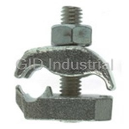
Grid GroundingLug-2 Bolt Hole-Flag Type 10102-TB
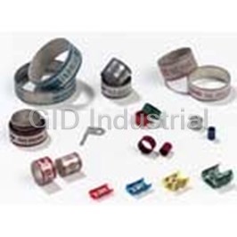
Connector Accessories DIE INSTALLING 101A
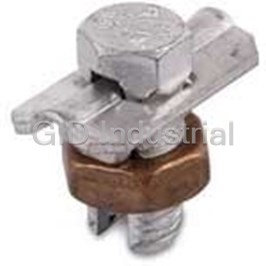
Connector Accessories Bolt Copper Alloy Electro Tin 10HPW
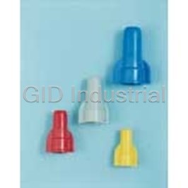
Connector Accessories Wire Connector Carton 1410KP
Connector Accessories Wire Connector Carton 1410P
Connector Accessories Bolt Copper Alloy Electro Tin 1HPW
Request a Quote

The quote request has been received
Close

Facing challenges or have inquiries? Feel free to contact us!
Call Us +1-469-283-2440
What they say about us
FANTASTIC RESOURCE
One of our top priorities is maintaining our business with precision, and we are constantly looking for affiliates that can help us achieve our goal. With the aid of GID Industrial, our obsolete product management has never been more efficient. They have been a great resource to our company, and have quickly become a go-to supplier on our list!
Bucher Emhart Glass
EXCELLENT SERVICE
With our strict fundamentals and high expectations, we were surprised when we came across GID Industrial and their competitive pricing. When we approached them with our issue, they were incredibly confident in being able to provide us with a seamless solution at the best price for us. GID Industrial quickly understood our needs and provided us with excellent service, as well as fully tested product to ensure what we received would be the right fit for our company.
Fuji
HARD TO FIND A BETTER PROVIDER
Our company provides services to aid in the manufacture of technological products, such as semiconductors and flat panel displays, and often searching for distributors of obsolete product we require can waste time and money. Finding GID Industrial proved to be a great asset to our company, with cost effective solutions and superior knowledge on all of their materials, it’d be hard to find a better provider of obsolete or hard to find products.
Applied Materials
CONSISTENTLY DELIVERS QUALITY SOLUTIONS
Over the years, the equipment used in our company becomes discontinued, but they’re still of great use to us and our customers. Once these products are no longer available through the manufacturer, finding a reliable, quick supplier is a necessity, and luckily for us, GID Industrial has provided the most trustworthy, quality solutions to our obsolete component needs.
Nidec Vamco
TERRIFIC RESOURCE
This company has been a terrific help to us (I work for Trican Well Service) in sourcing the Micron Ram Memory we needed for our Siemens computers. Great service! And great pricing! I know when the product is shipping and when it will arrive, all the way through the ordering process.
Trican Well Service
GO TO SOURCE
When I can't find an obsolete part, I first call GID and they'll come up with my parts every time. Great customer service and follow up as well. Scott emails me from time to time to touch base and see if we're having trouble finding something.....which is often with our 25 yr old equipment.
ConAgra Foods