

 Manufacturers
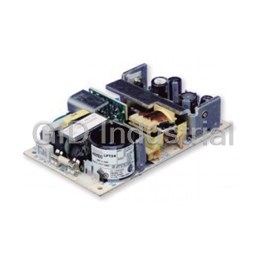
ARTESYN IMP4-3N0-INE0-LLN0-00-A

Description
IMP4-3N0-INE0-LLN0-00-A
Part Number
IMP4-3N0-INE0-LLN0-00-A
Price
Request Quote
Manufacturer
ARTESYN
Lead Time
Request Quote
Category
Circuit Protection » AC-DC Power Supply
Specifications
Manufacturer
Artesyn
Manufacturers Part #
IMP4-3N0-INE0-LLN0-00-A
Brand
Artesyn Embedded Technologies
Series
iMP
Factory Pack Quantity
1
Industry
Industrial, Medical
Mechanical Style
Modular
Mounting
Chassis Mount
Power
1158 W
Subcategory
AC-DC Power Supply
Datasheet

Extracted Text
POWER Intelligent MP Series Data Sheet Up to 1500 Watts Total Power: Up to 1500 W Input Voltage: 85 - 264 Vac 120 - 300 Vdc # of Outputs: Up to 21 SPECIAL FEATURES Full medical EN60601 approval 2 Intelligent I C control Voltage adjustment on all outputs 2 (manual or I C) Configurable input and output OK signals and indicators Electrical Specifications Configurable inhibit/enable Input Configurable output UP/DOWN Input ra nge 85 - 264 Vac; 120 - 300 Vdc sequencing (limited to 300 Vdc in medical applications) Configurable current limit Frequency 47 - 440 Hz (foldback or constant current) High power density (8.8 W/cu-in) Inrush current 40 A peak maximum (soft start) Intelligent fan (speed control/fault Efficiency Up to 85% @ full case load status) Power Factor 0.99 typ. meets EN61000-3-2 (n/a @ 440 Hz) Downloadable GUI from website Turn-on time AC on 2.0 sec typ., inhibit/enable 150 ms typical Customer provided air option Programmable delay; 50 ms internal turn-on delay (Dual Output only) uP controlled PFC input with active EMI filter CISPR 22/EN55022 Level “B”** inrush protection 2 I C monitor of voltage, current, and Leakage current 300 µA max. @ 240 Vac; 47 - 63 Hz temp Radiated EMI CISPR 22/EN55022 Level “B”** Programmable voltage, current limit, Holdover storage 20 ms minimum (independent of input Vac) additional 34 ms holdover 2 inhibit/enable through I C storage with optional HUP module (SEMI F47 compatible). Optional extended hold-up module For iMP4 15 ms (low-line), 10 ms (high-line) (SEMI F47 compliance) AC OK > 5 ms early warning min. before outputs lose regulation Increased power density to 50% over Full cycle ride thru (50 Hz) (n/a on iMP4 > 750 W @ 90 Vac) standard MP Harmonic distortion Meets EN61000-3-2 External switching frequency sync input Isolation Meets EN60950 and EN60601 Optional conformal coating Input to output, input to ground: 2000 Vac; output to ground: 400 Vdc Industrial temp range (-40 ºC to 70 ºC) Global inhibit / enable TTL, Logic “1” and Logic “0”; configurable No preload required Input fuse (internal) iMP4: 16 A; iMP8: 20 A; iMP1: 25 A (both lines fused) Industrial shock/vibration (> 50G’s) Warranty 2 years SAFETY UL UL60950/UL2601** CSA CSA22.2 No. 234 Level 5 UV EN60950/EN60601-1** BABT Compliance to EN60950/ EN60601 BS7002 CB Certificate and report CE Mark to LVD iMP Data Sheet Electrical Specifications Output Output (cont.) Adjustment range* ± 10% minimum all outputs (manual) Reverse voltage protection 100% of rated output current 2 (full module adjustment range using I C) 2 Thermal protection* Configurable through I C Factory set point accuracy 1% (OTP and OTW) All outputs disabled when internal temp 2 exceeds safe operating range. > 5 ms I C output program ± 5% warning (AC OK signal) before shutdown accuracy Remote sense Up to 0.5 V total drop (not available on triple Margining ± 4 - 6% nominal analog (single output output module) module only) Single wire parallel Current share to within 2% of total rated Overall regulation 0.4% or 20 mV max. (1500 W modules 1% current max.) (36 W modules 4% maximum) 2 DC OK* ± 5% of nominal. Configurable through I C Ripple RMS: 0.1% or 10 mV, whichever is greater Pk-Pk: 1.0% or 50 mV, whichever is greater Minimum load Not required Bandwidth limited to 20 MHz Housekeeping bias voltage 5 Vdc @ 1.0 A max. present whenever AC Dynamic response < 2% or 100 mV, with 25% load step input is applied (Optional 2.0 A available) 2 Recovery time To within 1% in < 300 µsec Module inhibit* Configured and controlled through I C 2 Overcurrent protection** Configurable through I C (calibration Switching frequency 250k Hz accepts external sync signal required). Single output module and main Output/Output isolation > 1 Megohm, 500 V output of the dual output module 105 - 120% External sync TTL clock input signal used to adjust of rated output current. Aux output of dual switching frequency. Frequency 500 kHz output module 105 - 140% of rated output ± 20%; Duty cycle 40 - 55% current 2 Short-circuit protection Protected for continuous short-circuit. * Can be controlled via I C 2 ** Controlled via I C but requires load calibration Recovery is automatic upon removal of short 2 Overvoltage protection* Configurable through I C Single output module: Internal Part Number Reference Table 2 - 5.5 V 122 - 134%; 6 - 60 V 110 - 120% Dual output module: Part # Where X = Description Module Code 2 - 6 V 122 - 134%; 8 - 28 V 110 - 120% 73-580-0001i N/A iMP8 Case iMP8 Triple output module: 73-690-0001i N/A iMP1 Case iMP1 110 - 120% of highest voltage rating Environmental Specifications Operating temperature -40 ° to 70 °C ambient. Derate each output 2.5% per degree from 50 ° to 70 °C. (-20 °C start up) Storage temperature -40 °C to +85 °C Electromagnetic susceptibility Designed to meet EN61000-4; -2, -3, -4, -5, -6, -8, -11 Level 3 Humidity Operating; non-condensing 10% to 95% RH Vibratio IEC68-2-6 to the levels of IEC721-3-2 MTBF demonstrated > 550,000 hours at full load, 220 Vac and 25 °C ambient conditions Output Module Line-up Module Code 1 2 3 5 4 — Module Type Single Single Single Single Dual Triple Max output power 210 W 360 W 750 W 1500 W 144 W 36 W Max output current 35 A 60 A 150 A 140 A 10 A 2 A Output voltages available* 2 - 60 V 2 - 60 V 2 - 60 V 6 - 60 V 8 - 15*, 24 - 28; 8 - 15*, 8 - 15*; 8-15, 8-15, 2-6; 8-15, 8-15, 8-15; 8 - 15*, 2 - 6; 2 - 6, 2 - 6; 24 - 28, 8-15, 8-15, 18-28; 8-15, 18-28, 2-6 24 - 28; 24 - 28, 2 - 6 Standard voltage increments 25 25 25 18 16 18 Remote sense Yes Yes Yes Yes Yes Yes No Remote margin Yes Yes Yes Yes No No No 2 V-Program - I C Control Yes Yes Yes Yes Yes Yes No Active Current Share Yes Yes Yes Yes Yes No No 2 Module Inhibit - I C Control Yes Yes Yes Yes Yes Yes Yes Module Inhibit - Analog Yes Yes Yes Yes Yes No No Overvoltage/Overcurrent protection Yes Yes Yes Yes Yes Yes Yes Minimum load required No No No No No No No Slots occupied in any iVS case 1 2 3 4 1 1 * Note: Contact Factory for extended range down to 6 V iMP Data Sheet Output Module Voltage/Current* Ordering Notes: Voltage Dual 2 I C Voltage Single Output Module Code Triple Output 1. The cases and modules of both MP and iMP series can Code Output*** Adjustment be interchanged to allow more flexibility. If intelligent Ranges**** 1 2 3 5 4 4 - - - modules are used with non-intelligent cases, a numeric code “4” is placed at the end of the module code (ex. 2 V A 35 A 60 A 150 A 300 A 10 A 10 A — — 2 A 1.8 - 2.2 4LL0 becomes 4LL4). 2.2 V B 35 A 60 A 150 A 300 A 10 A 10 A — — 2 A 2.0 - 2.4 2 2. USB to I C module order code 73-769-001 3 V C 35 A 60 A 150 A 300 A 10 A 10 A — — 2 A 2.7 - 3.3 3.3 V D 35 A 60 A 150 A 300 A 10 A 10 A — — 2 A 3.0 - 3.6 5 V E 35 A 60 A 150 A 300 A 10 A 10 A — — 2 A 4.5 - 5.5 Parallel Codes 5.2 V F 35 A 60 A 144 A 288 A 10 A 10 A — — 2 A 4.7 - 5.7 iMP4 5.5 V G 34 A 58 A 136 A 273 A 10 A 10 A — — 2 A 5.0 - 6.1 available slots 6.0 V H 23 A 42 A 97.5 A 250 A 10 A* 10 A* — — 2 A 5.4 - 6.6 iMP8 8.0 V I 20 A 36 A 84.4 A 187.5 A 10 A 4 A 1 A 1 A 1 A 7.2 - 8.8 available slots 10 V J 18 A 32 A 75 A 140 A 10 A 4 A 1 A 1 A 1 A 9.0 - 11.0 iMP1 11 V K 17 A 31 A 68 A 136.3 A 10 A 4 A 1 A 1 A 1 A 9.9 - 12.1 available slots 12 V L 17 A 30 A 62.5 A 125 A 10 A 4 A 1 A 1 A 1 A 10.8 - 13.2 7 6 5 4 3 2 1 14 V M 14 A 21 A 53.5 A 107 A 9 A 4 A 1 A 1 A 1 A 12.6 - 15.4 0 = no parallel 15 V N 14 A 20 A 50 A 100 A 8 A 4 A 1 A 1 A 1 A 13.5 - 16.5 1 = 1 & 2 18 V O 11 A 19 A 41.6 A 83.3 A — — — 0.5 A 0.5 A 16.2 - 19.8 2 = 2 & 3 20 V P 10.5 A 18 A 37.5 A 75 A — — — 0.5 A 0.5 A 18.0 - 22.0 3 = 3 & 4 24 V Q 8.5 A 15 A 30 A 62.5 A 4 A 2 A — 0.5 A 0.5 A 21.6 - 26.4 4 = 4 & 5 28 V R 6.7 A 11 A 26.8 A 53.5 A 3 A 2 A — 0.5 A 0.5 A 25.2 - 30.8 5 = 3 & 4 & 5 30 V S 6.5 A 11 A 25 A 50 A — — — — — 27.0 - 33.0 6 = 5 & 6 33 V T 6.2 A 10.9 A 22.7 A 35.8 A — — — — — 29.7 - 36.3 7 = 4 & 5 & 6 36 V U 5.8 A 10 A 20.8 A 35.8 A — — — — — 32.4 - 39.6 8 = 6 & 7 42 V V 4.2 A 7.5 A 16 A 35.7 A — — — — — 37.8 - 46.2 9 = 3 & 4, 6 & 7 48 V W 4.0 A 7.5 A 15.6 A 31.2 A — — — — — 43.2 - 52.8 A = 1 & 2, 3 & 4, 5 & 6 54 V X 3.7 A 6.0 A 13.9 A 27.7 A — — — — — 48.6 - 59.4 C = 2 & 3, 4 & 5 60 V Y 3.5 A 6.0 A 12.5 A 25 A — — — — — 54.0 - 66.0 E = 3 & 4, 5 & 6 Contact Factory F = 2 & 3, 4 & 5, 6 & 7 Special* Z 35 A 60 A 150 A 300 A — 10 A 2.3 - 2.6 Special* Z 35 A 60 A 150 A 300 A — 10 A 3.7 - 4.4 Special* Z 20 A 36 A 80 A 140 A — 8 A 6.7 - 7.1 * Note: Contact Factory for extended range down to 6 V. ** Increments of current not shown can be achieved by paralleling modules (add currents of each module selected). *** Total output power on dual model must not exceed 144 W. **** For single output modules only. Green reference lines indicate physical module groupings Ordering Information Module/Voltage/Option Codes First - Module Code Second - Voltage Code Case Size Case Option Codes Software Code Hardware Code Third - Option Code iMP1* - 3L0 - 2E2 - 1Q1 - 4LL0 - 00 - A - ### Case Size (mm) Module Codes Case Option Codes Software code Factory assembled 4 = 2.5” x 5” x 10”; 750 W - 1158 W, 5 Slots Module/voltage/option codes used for for hardware of (63.5 x 127 x 254 mm) Module codes: First digit configuration firmware mods. 8 = 2.5” x 7” x 10”; 1000 W - 1200 W, (None) = 36 W triple O/P (1 slot) 0 - 9, A - Z parallel code change. “A” is 6 Slots (63.5 x 177.8 x 254 mm) 1 = 210 W single O/P (1 slot) (See Parallel Codes table above) standard 1 = 2.5” x 8” x 11”; 1200 W - 1500 W, 2 = 360 W single O/P (2 slot) 7 Slots (63.5 x 203.2 x 279.4 mm) 3 = 750 W single O/P (3 slot) Second digit 4 = 144 W dual O/P (1 slot) 0 = No options 5 = 1500 W single O/P (4 slot) 1 = Reverse air * Note: Add “E” after iMP4 to denote IEC input option. 6 - 9 = future 3 = Global enable e.g. iMP4E (Not available on iMP8 or iMP1) 4 = Fan idle with inhibit Voltage Codes: 5 = Opt 1 + Opt 3 See Output Module Voltage/Current table above 6 = Opt 1 + Opt 4 Option Codes: 7 = Opt 3 + Opt 4 0 = Standard 8 = Opt 1 +3 +4 1 = Module enable 9 = RS485 73-544-002 2 = Constant current A = RS485 73-544-002 + 3 = 1 & 2 combined Reverse air 4 = Set for use in standard C = Opt 3 + Opt 9 (non-intelligent case) D = CAN BUS 73-544-003 5 = Shutdown mode for 1500 W E = Opt 3 + Opt D 6 = 1 & 5 combined 7 - 9 = future Slot 7 Slot 6 Slot 6 Slot 5 Slot 5 Slot 5 Slot 4 Slot 4 Slot 4 Slot 3 Slot 3 Slot 3 Slot 2 Slot 2 Slot 2 Slot 1 Slot 1 iMP Data Sheet iMP4 (AC input on opposite side) Single S S S S S L L L L L O O O O O T T T T T 5 4 32 1 Input -A- 90 - 264 Vac 180 - 264 Vac iMP4 = 2.5” x 5” x 10” 5 available slots 750 W max. 1158 W max. 210 W 360 W (63.5 x 127 x 254 mm) iMP8 and iMP1 S S S S S S S L L L L L L L O O O O O O O T T T T T T T 750 W 7 6 5 4 3 2 1 iMP1 only Input 85 - 264 Vac 180 - 264 Vac iMP8 = 2.5” x 7” x 10” 6 available slots 1000 W max. 1200 W max. (63.5 x 177.8 x 254 mm) iMP1 = 2.5” x 8” x 11” 7 available slots 1200 W max. 1500 W max. (63.5 x 203.2 x 279.4 mm) Pin Connectors 1500 W ( 2.0 - 8.0 V) Figure 1. AC Input AC Input Pin No. Function N 1 1 AC neutral 2 ~ 2 AC line (hot) 3 3 Chassis (earth) ground PFC Input Connector (control and signals) Pin No. Function Figure 2. Connector J1 1 Input AC OK - “emitter” 2 Input AC OK - “collector” 5 1500 W ( 10 - 60 V) 3 Global DC OK - “emitter” 10 4 Global DC OK - “collector” 5 External Sync Mates with Molex 90142-0010 Housing 6 Global inhibit/optional enable logic “0” 1500 W with Bus Bar 90119-2110 Pin 7 Global inhibit/optional enable logic “1” Adapter Option (used with 8 Global inhibit/optional enable return Connector Kit Part No.: the 10 - 60 V module) 70-841-004 9 +5 VSB housekeeping 10 +5 VSB housekeeping return Figure 3. Connector J2 2 I C Bus Output Connector Pin No. Function Dual Triple 10 6 1 No connection 5 1 2 No connection 3 No connection Mates with Landwin 2050S1000 Housing 4 Serial clock signal (SCL) 2053T011V Pin 5 Serial data signal (SDA) or 6 Address bit 0 (A0) JST PHDR-10VS Housing 7 Address bit 1 (A1) JST SPHD-002T-P0.5 (28-24) JST SPHD-001T-P0.5 (26-22) 8 Address bit 2 (A2) 144 W 9 Secondary return (GND) 36 W Connector Kit Part No.: 10 5 Vcc external bus (5 VCC. Bus) 70-841-023 .33” (8 5) . .44” (11.2 ) 2X .32" (8.1) .63” (16.0) .32” (8.1) .63" (16.0) .59" (15.0) .32" (8.1) iMP Data Sheet Mechanical Drawings Single 210 Watt iMP Modules DC-DC Converter Output Modules V+ Control Signal Information, J1 Control Connector Pin No. Function M4X8 SCREWS WITH CONICAL WASHER 1 + Remote Sense single or dual o/p main 2 Remote Margin / V. Program single o/p V- N 1 3 Margin High single o/p 4 - Remote Sense / Margin Low single or dual o/p main V ADJ 2 ~ 5 Spare PIN 1 3 6 Module, Isolated Inhibit single or dual o/p DC OUTPUT CONNECTOR 7 Module Inhibit Return single or dual o/p 8 Current Share (SWP) single or dual o/p main 9 + Remote Sense V2 dual o/p, single is spare Figure 1. AC Input Single 360 Watt 10 - Remote Sense V2 dual o/p, single is spare V+ * Note: All iMP modules have a green DCOK LED. (except for 36 W module) M 4 X 8 SCREWS Figure 4. Connector J1 WITH CONICAL WASHER Mates with V- 5 Molex 90142-0010 Housing 1 PIN 1 90119-2110 Pin 6 10 V ADJ Figure 2. Connector J1 DC OUTPUT CONNECTOR Single 750 Watt Single 1500 Watt 2-8 V Single 1500 Watt 10-60 V 59.3 ± 0.2 V+ (3x) 31.6 ±0.8 11.3 ±0.8 8.1 ±0.8 (2x) 15.0 ±0.8 DC OUTPUT CONNECTOR (2x) 16.0 ±0.2 PIN 1 (2x) 16.0 ±0.2 For Factory-Use Only M4X8 SCREWS W/ CONICAL WASHER (6X) VADJ V- V ADJ M4X8 SCREWS PIN 1 (4X) V- DC OUTPUT CONNECTOR V+ Dual 144 Watt Triple 36 Watt V1 + V1 ADJ .46 (11.7) (4X) V2 ADJ V1 - V1 + V2 + V1+ V1 - V1- V2+ V2 + V2 - V2- .30 (7.5)(3X) V3+ V2 - V3- M3X8 SCREWS WITH SPRING WASHER V3 + (4X) V3 ADJ V3 - 1.17 (29.7) V2 ADJ .42 (10.7) Mates with V1 ADJ Molex 09-91-0600 Housing .32 (8.1) 26-60-5060 Pin PIN 1 .61"(15.6) 1.24"(31.5) (2X) (2X) .44" (11.0) .48" (12.1) .44" (11.4) .48” (12.1) 1.38” (35.2) (2X) (2X) .44” (11.4) 1.38" (35.1) iMP Data Sheet iMP Series 5-Inch Case Size: iMP4: 2.5” x 5” x 10” (63.5 mm x 127 mm x 254 mm) iMP4 (750/1158 Watts Max) Weight: iMP4 Case: 3 lbs. • 360 W Single 1.0 lb. • 750 W Single: 1.6 lbs. 144 W Dual: 0.6 lb. Notes: 1. Input: Barrier type. Three No. 6-32 B.H. screws (0.375” centers). Max torque: 6 in-lbs. (0.67 N-m). (Optional IEC input connector) 2. Control connectors: (J1) 10 position housing, gold plated contacts. Mates with Molex 90142-0010 housing with 90119-2110 crimp contacts (Molex C - Grid III Series). Connector kit includes mating connector and 10 pins, Astec part #70-841-004. (J2) 10 position housing (Landwin 2051P1000T). Mates with housing 2050S1000 (Landwin) with 2053T011P (Landwin) pins or JST PHDR-IOVS Housing and JST SPHD-002T-PO.5 pins. 3. Chassis material: aluminum with chemical film coating (conductive). 4. All dimensions are in millimeters and inches, and are typical. 5. Customer mounting -3 sides M4, bottom also includes 8-32 mounting holes. Max. penetration is 0.150” (3.8 mm). Max. torque: 5 in-lbs. (0.57 N-m). 6. Output module connections: All single O/P modules are M4 x 8 mm screws. Max. torque: 10 in-lbs. (1.13 N-m). Dual O/P module is M3 x 8 mm screws. Max. torque: 5 in-lbs. (0.57 N-m). iMP Data Sheet iMP Series 7-Inch Case Size: iMP8: 2.5” x 7” x 10” (63.5 mm x 177.8 mm x 254 mm) iMP8 (1000/1200 Watts Max) Weight: iMP8 Case: 4.1 lbs. • 210 W Single: 0.6 lb. • 360 W Single: 1.0 lb. • 750 W Single: 1.6 lbs. 144 W Dual: 0.6 lb. Notes: 1. Input: Barrier type. Three No. 6-32 B.H. screws (0.375” centers). Max torque: 6 in-lbs. (0.67 N-m). 2. Control connectors: (J1) 10 position housing, gold plated contacts. Mates with Molex 90142-0010 housing with 90119-2110 crimp contacts (Molex C - Grid III Series) Connector kit includes mating connector and 10 pins, Astec part #70-841-004. (J2) 10 position housing (Landwin 2051P1000T). Mates with housing 2050S1000 (Landwin) with 2053T011P (Landwin) pins or JST PHDR-IOVS Housing and JST SPHD-002T-PO.5 pins. 3. Chassis material: aluminum with chemical film coating (conductive). 4. All dimensions are in millimeters and inches, and are typical. 5. Customer mounting -3 sides M4, bottom also includes 8-32 mounting holes. Max. penetration is 0.150” (3.8 mm). Max. torque: 5 in-lbs. (0.57 N-m). 6. Output module connections: All single O/P modules are M4 x 8 mm screws. Max. torque: 10 in-lbs. (1.13 N-m). Dual O/P module is M3 x 8 mm screws. Max. torque: 5 in-lbs. (0.57 N-m). Normal Air Flow Reverse Air Flow M4 MOUNTING HOLES (4X) IDENTICAL BOTH SIDES 171.45 38.10 #8-32 MOUNTING HOLES (4X) MARKED AS Y 171.45 xx y y 177.8 x y x y M4 MOUNTING HOLES (4X) 19.05 MARKED AS X iMP Data Sheet iMP Series 8-Inch Case Size: iMP1: 2.5” x 8” x 11” (63.5 mm x 203.2 mm x 279.4 mm) iMP1 (1200/1500 Watts Max) Weight: iMP1 Case: 5.0 lb. • 210 W Single: 0.6 lb. • 360 W Single: 1.0 lb. • 750 W Single: 1.6 lb. • 144 W Dual: 0.6 lb. Normal Air Flow Reverse Air Flow M4 MOUNTING HOLES (4X) IDENTICAL BOTH SIDES 171.45 38.10 #8-32 MOUNTING HOLES (4X) MARKED AS Y 171.45 xx y y 177.8 x y x y M4 MOUNTING HOLES (4X) 19.05 MARKED AS X Notes: 1. Input: Barrier type. Three No. 6-32 B.H. screws (0.375” centers). Max torque: 6 in-lbs (0.67 N-m). 2. Control connectors: (J1) 10 position housing, gold plated contacts. Mates with Molex 90142-0010 housing with 90119-2110 crimp contacts (Molex C - Grid III Series). Connector kit includes mating connector and 10 pins, Astec part #70-841-004. (J2) 10 position housing (Landwin 2051P1000T). Mates with housing 2050S1000 (Landwin) with 2053T011P (Landwin) pins or JST PHDR-IOVS Housing and JST SPHD-002T-PO.5 pins. 3. Chassis material: aluminum with chemical film coating (conductive). 4. All dimensions are in millimeters and inches, and are typical. 5. Customer mounting -3 sides M4, bottom also includes 8-32 mounting holes. Max. penetration is 0.150” (3.8 mm). Max. torque: 5 in-lbs. (0.57 N-m). 6. Output module connections: All single O/P modules are M4 x 8 mm screws. Max. torque: 10 in-lbs. (1.13 N-m). Dual O/P module is M3 x 8 mm screws. Max. torque: 5 in-lbs. (0.57 N-m). iMP Data Sheet Optional CANBUS or RS485 Interface 2 The RS485/CAN-to-I C uses 2 Input Protocols and 1 Slave/Server Device(s) Output Protocol. The Input Protocols used are RS485 using Modbus Adapter (Command Index: 0x01), and CAN using modified Modus (Command Index: 0x02). Output Protocols 2 I C with SMBus 2 The Output Protocol use is: I C with SMBus support Support (Command Index: 0x80). Adapter Protocol Adapter Command Adapter Controls Input Protocols RS485 using CAN using Modbus Modi ed Modbus Master/Client Device(s) 2 RS485/CAN - to - I C For detailed info, download the Software Requirements Specification (SRS) from http://www.artesyn.com/power/power- supplies/cat/101/Configurable-Power-Supplies-iMP-Series iMP CAN RS485 WORLDWIDE OFFICES Americas Europe (UK) Asia (HK) 2900 S.Diablo Way Waterfront Business Park 14/F, Lu Plaza Tempe, AZ 85282 Merry Hill, Dudley 2 Wing Yip Street USA West Midlands, DY5 1LX Kwun Tong, Kowloon +1 888 412 7832 United Kingdom Hong Kong www.artesyn.com +44 (0) 1384 842 211 +852 2176 3333 For more information: www.artesyn.com/power Artesyn Embedded Technologies, Artesyn and the Artesyn Embedded Technologies logo are trademarks and For support: productsupport.ep@artesyn.com service marks of Artesyn Embedded Technologies, Inc. All other names and logos referred to are trade names, trademarks, or registered trademarks of their respective owners. Specifications are subject to change without notice. © 2018 Artesyn Embedded Technologies, Inc. All rights reserved. For full legal terms and conditions, please visit www.artesyn.com/legal. iMP DS 24Jan2018
Frequently asked questions
How does Electronics Finder differ from its competitors?

Is there a warranty for the IMP4-3N0-INE0-LLN0-00-A?
Which carrier will Electronics Finder use to ship my parts?
Can I buy parts from Electronics Finder if I am outside the USA?
Which payment methods does Electronics Finder accept?
Why buy from GID?

Quality
We are industry veterans who take pride in our work

Protection
Avoid the dangers of risky trading in the gray market

Access
Our network of suppliers is ready and at your disposal

Savings
Maintain legacy systems to prevent costly downtime

Speed
Time is of the essence, and we are respectful of yours
Related Products
LPX25, LPX40, LPX50, LPX60, NPS20-M, NPS40-M AND NPS60-M MATING CONNECTOR KIT 70-841-006
73-560-5090
Artesyn Embedded Technologies
Artesyn Embedded Technologies
uMP16T-S2Q-S2Q-S2Q-S2Q-S2Q-S2Q-03-B
100 W, Single Output, 48 V@2.08 A OEM/Commercial Desktop AC-DC Power Supply AD10048P3L-001
Request a Quote

The quote request has been received
Close

Facing challenges or have inquiries? Feel free to contact us!
Call Us +1-469-283-2440
What they say about us
FANTASTIC RESOURCE
One of our top priorities is maintaining our business with precision, and we are constantly looking for affiliates that can help us achieve our goal. With the aid of GID Industrial, our obsolete product management has never been more efficient. They have been a great resource to our company, and have quickly become a go-to supplier on our list!
Bucher Emhart Glass
EXCELLENT SERVICE
With our strict fundamentals and high expectations, we were surprised when we came across GID Industrial and their competitive pricing. When we approached them with our issue, they were incredibly confident in being able to provide us with a seamless solution at the best price for us. GID Industrial quickly understood our needs and provided us with excellent service, as well as fully tested product to ensure what we received would be the right fit for our company.
Fuji
HARD TO FIND A BETTER PROVIDER
Our company provides services to aid in the manufacture of technological products, such as semiconductors and flat panel displays, and often searching for distributors of obsolete product we require can waste time and money. Finding GID Industrial proved to be a great asset to our company, with cost effective solutions and superior knowledge on all of their materials, it’d be hard to find a better provider of obsolete or hard to find products.
Applied Materials
CONSISTENTLY DELIVERS QUALITY SOLUTIONS
Over the years, the equipment used in our company becomes discontinued, but they’re still of great use to us and our customers. Once these products are no longer available through the manufacturer, finding a reliable, quick supplier is a necessity, and luckily for us, GID Industrial has provided the most trustworthy, quality solutions to our obsolete component needs.
Nidec Vamco
TERRIFIC RESOURCE
This company has been a terrific help to us (I work for Trican Well Service) in sourcing the Micron Ram Memory we needed for our Siemens computers. Great service! And great pricing! I know when the product is shipping and when it will arrive, all the way through the ordering process.
Trican Well Service
GO TO SOURCE
When I can't find an obsolete part, I first call GID and they'll come up with my parts every time. Great customer service and follow up as well. Scott emails me from time to time to touch base and see if we're having trouble finding something.....which is often with our 25 yr old equipment.
ConAgra Foods