

 Manufacturers
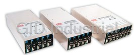
ARTESYN MP8-3I-3I-00
Description
Artesyn Embedded Technologies
Part Number
MP8-3I-3I-00
Price
Request Quote
Manufacturer
ARTESYN
Lead Time
Request Quote
Category
Circuit Protection » AC-DC Power Supply
Specifications
Manufacturer
Artesyn
Manufacturers Part #
MP8-3I-3I-00
Brand
Artesyn Embedded Technologies
Series
MP
Factory Pack Quantity
1
Industry
Industrial
Mechanical Style
Modular
Mounting
Chassis Mount
Power
1000 W
Subcategory
AC-DC Power Supply
Datasheet

Extracted Text
POWER MP Series Data Sheet 400 - 1200 Watts Total Power: 400 - 1200 W Input Voltage: 85 - 264 VAC 120 - 350 VDC # of Outputs: Up to 21 Special featureS Currentshareonalloutputswith ratingsof10Aorgreater Remotesenseonalloutputswith ratingsgreaterthan2A Electrical Specifications Overloadprotectiononalloutputs Voltageadjustmentonalloutputs Input Marginingonallsingleoutputmodules Input ra nge: 85 - 264 Vac InputOKsignalandstatusindicatorLED 120 - 350 Vdc GlobalDCOKsignalandstatusindicatorLED Frequency: 47 - 440 Hz Globalandindividualmoduleinhibits/enable Inrush current: 40 A peak max. (soft start) 2yearwarranty Forcedaircooling,fieldreplaceablefan Efficiency: 70 - 80% typ. @ full case load Isolated5Vbiasvoltage Power factor: 0.99 typ. meets EN61000-3-2 Powerfactorcorrection AC on 1.5 sec typ. Turn-on time: EN61000-3-2harmonicdistortioncompliance inhibit/enable 150 ms typ. CISPR22,EN55022CurveBconducted/ EMI filter standard: CISPR 22/EN55022 Level “B” radiatedEMI EMI filter (low leakage option): CISPR 22/EN55022 Level “A” EuropeanCEMarkrequirements OptionalVMEtimingandsystemDCOK Leakage current standard: 2.0 mA max. @240 Vac module Leakage current (low leakage option): 300μA max. @ 240 Vac Customer-providedairoption Radiated EMI: CISPR 22/EN55022 Level “B” Additional200Woutput@highline (180-264VAC) Holdover storage: 20 ms minimum (independent of input Vac) Lowleakageoptionformedicalapplications AC OK: > 5 ms early warning min. before outputs lose regulation EN61000immunitystandards Full cycle ride thru (50 Hz) Standardmodificationflexibility Harmonic distortion: Meets EN61000-3-2 (consultfactory) •Lownoisefan Isolation: Meets EN60950 •Fanfailsignal Efficiency: 70 - 80% typ. @ full case load •Moduleenable •Outputsdownto0.5V Global Inhibit/Enable: TTL, Logic “1” and Logic “0” FieldDemonstratedMTBF:>550,000hours Input fuse (internal): MP4: 10 A; MP6: 15 A; MP8: 20 A; MP1: 20 A atfullload,220Vac&25°Cambient Warranty: 2 years conditions SafetY UL UL1950 CSA CSA22.2No.234Level5 IEC IEC950,Class1 VDE EN60950 BABT CompliancetoEN60950, BS7002 CB Certificateandreport CE Mark MP Series Data Sheet Electrical Specifications Electrical Specifications Electrical Specifications Output Output (cont.) Adjustment range: ± 10% minimum all outputs All outputs disabled when internal temp exceeds Thermal protection: safe operating range. > 5 ms warning (AC OK 1 Margining: ± 4 - 6% nominal signal) before shutdown Overall regulation: 0.4% or 20mV max. Up to 0.5 V total drop (not avbl on triple output (36 W modules 4% maximum) Remote sense: module) RMS: 0.1% or 10 mV, whichever is greater 2 Single wire parallel: Current share to within 2% of total rated current Ripple: Pk-Pk: 1.0% or 50 mV, whichever is greater 2 Bandwidth limited to 20 MHz DC OK: -2% to -8% of nominal for any monitored output Dynamic response: < 2% or 100 mV, with 25% load step Minimum load: Not required on single or triple output. 10% 3 required on main of dual output Recovery time: To within 1% in < 300 μsec Housekeeping bias 5 Vdc @ 1.0 A max. present whenever AC input Overcurrent protection:** Single output module & main output of dual voltage: is applied output module Module inhibit: TTL, isolated, singles and dual (both outputs) 105-120% of rated output current. only Aux output of dual output module 105 -140% Switching frequency: 250k Hz of rated output current Output/Output isolation: > 1 Megohm Short-circuit protection: Protected for continuous short-circuit VME signal option board: POR signal & quad external DC OK Recovery auto upon removal of short 1-slot module providing additional 34 mSec Overvoltage protection: Single output module: 2 - 5.5 V 122 - 134%; Hold-up module (HUP): (60 mSec total); hold-up @ 600 W loading. (measured at sense 6 - 60 V 100 - 120% connection) > 550,000 hours at full load, 220 Vac and Dual output module: 2 - 6 V 122 - 134%; Field Demonstrated MTBF: 25 °C ambient conditions 8 - 28 V 110 - 120% 1. Single output modules only. Triple output module: No overvoltage 2. Single and main of dual output modules only protection provided. Recycle AC input voltage to reset OVP circuit 3. Contact factory for optional preload if required Reverse voltage protection: 100% of rated output current Environmental Specifications Operating temperature: -20 °C to 50 °C (start @ 0 °C) (derate each output linearly to 50% at 70 °C) (-20 °C to 40 °C max. with rear air option) Shock/Vibration: Mil-Hdbk 810E Humidity: 95% non-condensing Storage temperature: -40 °C to 85 °C Temperature coefficient: 0.02% per °C Cooling: Internal DC fan or customer provided air (option) Output Module Line-up Module Type Single Single Single Dual Triple Output: 1 1 2 3 Max output power: 210 W 360 W 600 W 144 W 36 W 120 mV Max output current: 35 A 60 A 120 A 10 A 2 A Volts: 2 - 60 V 2 - 60 V 2 - 60 V 2 - 28 V 2 - 28 V Standard voltage increments: 25 25 25 19 18 Remote sense on outputs: Yes Yes Yes Yes, both No Remote margin/V-Program: Yes Yes Yes No No Module Inhibit (isolated): Yes Yes Yes – – Single wire active current share: Yes Yes Yes Yes, main only – Over voltage/over current protection: Yes Yes Yes Yes Over current Minimum load required: No No No Yes (10%) main only No Slots occupied in any MP case: 1 2 3 1 1 MP Series Data Sheet Output Module Voltage/Current Voltage Voltage Single Output Module Code Dual Output** Triple Output Parallel Codes Code MP4 & MP6 1 2 3 V1 V2 V1 V2 V3 available slots 2 V A 35 A 60 A 120 A — 10 A — — 2 A MP8 2.2 V B 35 A 60 A 120 A — 10 A — — 2 A available slots 3 V C 35 A 60 A 120 A — 10 A — — 2 A MP1 3.3 V D 35 A 60 A 120 A — 10 A — — 2 A available slots 5 V E 35 A 60 A 120 A 10 A 10 A — — 2 A 7 6 5 4 3 2 1 5.2 V F 35 A 60 A 115 A — 10 A — — 2 A 0 = no parallel 5.5 V G 34 A 58 A 109 A — 10 A — — 2 A 1 = 1 & 2 6.0 V H 23 A 42 A 78 A — 10 A — — 2 A 2 = 2 & 3 8.0 V I 20 A 36 A 68 A — — 1 A 1 A 1 A 3 = 3 & 4 10 V J 18 A 32 A 60 A — — 1 A 1 A 1 A 4 = 4 & 5 11 V K 17 A 31 A 54.5 A — — 1 A 1 A 1 A 5 = 3 & 4 & 5 12 V L 17 A 30 A 50 A 10 A 4 A 1 A 1 A 1 A 6 = 5 & 6 14 V M 14 A 21 A 40.5 A 9 A 4 A 1 A 1 A 1 A 7 = 4 & 5 & 6 15 V N 14 A 20 A 39 A 8 A 4 A 1 A 1 A 1 A 8 = 6 & 7 18 V O 11 A 19 A 33.3 A — — — 0.5 A 0.5 A 20 V P 10.5 A 18 A 30 A — — — 0.5 A 0.5 A 9 = 3 & 4, 6 & 7 24 V Q 8.5 A 15 A 23.5 A 4 A 2 A — 0.5 A 0.5 A A = 1 & 2, 3 & 4, 5 & 6 28 V R 6.7 A 12.8 A 21.4 A 3 A 2 A — 0.5 A 0.5 A C = 2 & 3, 4 & 5 30 V S 6.5 A 12 A 20 A — — — — — E = 3 & 4, 5 & 6 33 V T 6.2 A 10.9 A 18.2 A — — — — — F = 2 & 3, 4 & 5, 6 & 7 36 V U 5.8 A 10 A 16.6 A — — — — — Notes: 42 V V 4.2 A 7.5 A 12.5 A — — — — — 1. Omit digits that do not apply. 48 V W 4.0 A 7.5 A 12.5 A — — — — — 2. Specify modules from lowest number of outputs to highest. (Single/Dual/Triple) 54 V X 3.7 A 6.0 A 11 A — — — — — 3. If number of outputs are equal, specify modules from highest to lowest power 60 V Y 3.5 A 6.0 A 10 A — — — — — increments. If power increments are equal, specify in descending alphabetical Non-std* Z Special Voltage - Consult Factory for specifications order (1A, B, C . . .). 2.4 - 2.7 V 35 A 60 A 120 A — 10 A — — 2 A 4. Always start with Slot 1. 5. All MP model configurations created using this selection guide are standard MP 3.6 - 4.5 V 35 A 60 A 120 A — 10 A — — 2 A products with standard availability and lead times. 6.6 - 9.2 V 20 A 36 A 68 A 10 A 4 A — — 1 A 6. Optional VME/DCOK module must always be located in the last slot. Module 8.8 - 9.0 V 18 A 32 A 60 A 10 A 4 A — — 1 A designator is “VME”. Ordering Information Case Size Module/Voltage/Option Codes Add-on Modules Hardware Code Case Option Codes First - Module Code Second - Voltage Code MP1 - 3L - 2E - 1Q - 4LL - HUP - 00 -### HUP = Hold up module Case Option Codes Case Size (mm) Module Codes Factory assigned VME = VME POR signal 4 = 2.5” x 5” x 10”; 400 - 600 W, 5 Slots Module/Voltage/Option Codes for modifications and isolated DC First digit (63.5 x 127 x 254) Module codes: 0 - 9, A - Z parallel code 6 = 2.5” x 5” x 11”; 600- 800 W, 5 Slots (None) = 36 W triple O/P (1 slot) (See Parallel Codes table above) (63.5 x 127 x 279.4) 1 = 210 W single O/P (1 slot) 8 = 2.5” x 7” x 10”; 800 - 1000 W, 6 Slots 2 = 360 W single O/P (2 slot) Second digit (63.5 x 177.8 x 254) 3 = 600 W single O/P (3 slot) Standard Options 1 = 2.5” x 8” x 11”; 1000 - 1200 W, 7 Slots* 4 = 144 W dual O/P (1 slot) 0 = No options (63.5 x 203.2 x 279.4) 5 - 9 = future 1 = Rear Air Exhaust Voltage Codes: 3 = Global enable See Output Module Voltage/ 5 = Opt 1 + Opt 3 Current table above M = Low Leakage N = Low Leakage + Opt 1 P = Low Leakage + Opt 3 R = Low Leakage + Opt 5 Slot 7 Slot 6 Slot 6 Slot 5 Slot 5 Slot 5 Slot 4 Slot 4 Slot 4 Slot 3 Slot 3 Slot 3 Slot 2 Slot 2 Slot 2 Slot 1 Slot 1 MP Series Data Sheet MP4 & MP6 Single 4.3 ± .8 -A- 23.9 ± .5 (4 PL) .17 ± .03 .94 ± .02 NON-CUMULATIVE Input 85-264 Vac 180-264 Vac MP4 = 2.5” x 5” x 10” 5 available slots 400 W max. 600 W max. 210 W (63.5 x 127 x 254 mm) MP6 = 2.5” x 8” x 11” 5 available slots 600 W max. 800 W max. (63.5 x 127 x 279.4 mm) MP8 177.8 7.0 S S S S S S AC INPUT L L L L L L O O O O O O T T T T T T 360 W 6 5 4 3 2 1 OUTPUT MODULE AREA Input 85-264 Vac 180-264 Vac MP8 = 2.5” x 7” x 10” 6 available slots 800 W max. 1000 W max. (63.5 x 177.8 x 254 mm) MP1 600 W Dual Input 85-264 Vac 180-264 Vac MP1 = 2.5” x 8” x 11” 7 available slots 1000 W max. 1200 W max. (63.5 x 203.2 x 279.4 mm) Pin Connectors 144 W Figure 1. Connector J1 PFC Input Connector J1 Control Connector Standard for all cases Pin No. Function J1-1 Input AC OK - “emitter” Triple J1-2 Input AC OK - “collector” J1-3 Global DC OK - “emitter” Mates with J1-4 Global DC OK - “collector” Molex 90142-0010 Housing J1-5 Spare 90119-2110 Pin J1-6 Global inhibit/optional enable logic “0” J1-7 Global inhibit/optional enable logic “1” J1-8 Global inhibit/optional enable return J1-9 SELV 5 V housekeeping J1-10 SE:V 5 V housekeeping return MP Series Data Sheet Mechanical Drawings Mp Modules DC-DC Converter Output Modules Single 210 Watt .44 (11.2 ) V+ PFC Input Connector (2X) Pin No. Function 1 + Remote Sense single or dual o/p main M4X8 SCREWS (2X) 2 Remote Margin / V. Program single o/p N 1 3 Margin High single o/p 4 - Remote Sense/Margin Low single or dual o/p main .48 (12.1) 2 ~ V- 5 Spare 3 6 Module, Isolated Inhibit single or dual o/p 7 Module Inhibit Return single or dual o/p 1.38 V ADJ 8 Current Share (SWP) single or dual o/p main (35.1) 9 + Remote Sense V2 dual o/p, single is spare 10 - Remote Sense V2 dual o/p, single is spare .44 (11.3) PIN 1 Figure 4. Connector J1 .32 (8.1) Mates with 1 5 Molex 90142-0010 Housing 90119-2110 Pin 6 10 Single 600 Watt .63 V+ Single 360 Watt (16.0) .59 .63 (16.0) (15.0) V+ .33 (8.5) M4X8 SCREWS (4X) M4X8 SCREWS (4X) V- V- PIN 1 V ADJ V ADJ .32 PIN 1 (8.1) .32 (8.1) Triple 36 Watt Dual 144 Watt V1 + .46 (11.7) V1 ADJ (4X) V1 - V1+ V1- V2 + V2+ V2 ADJ V2- V2 - V3+ .30 (7.5)(3X) V3- PIN 1 M3X8 SCREWS (4X) 1.17 (29.7) DC OUTPUT CONNECTION V2 ADJ .42 (10.7) V1 ADJ V3 ADJ .48 .32 (8.1) (12.1) PIN 1 .48 (12.1) 1.38 (35.1) (2X) (2X) .44 (11.3) .61 (15.6) .84 (2X) (21.3) 1.24 (31.6) (2X) .44 (11.3) MP Series Data Sheet MP Series MP4 (400/600 Watts Max) 5-Inch Case Size: MP4: 2.5” x 5” x 10” (63.5 mm x 127mm x 254 mm) MP6 (600/800 Watts Max) 5-Inch Case Size: MP6: 2.5” x 5” x 11” (63.5 mm x 127 mm x 279.4mm) Weight: MP4 Case: 2.6 lbs. • MP6 Case: 3.2 lbs. • 36 W Triple: 0.5 lb.• 210 W Single: 0.6 lb • Single O/P: 0.22 lb. • Dual O/P: 0.16 lb. • Blank: 0.06 lb. #8-32 MTG HOLES 4 PL 171.45 19.05 MARKED "A" 6.750 .750 M4 MTG HOLES 4 PL MARKED "B" B B A Standard Airow 101.60 4.000 B B A A 29.05 171.45 12.70 6.750 1.144 .500 3.5 (TYP ) .14 M4 MTG HOLES 4 PL +.0 38.10 63.5 -.5 1.500 +.00 2.50 -.02 171.45 19.05 12.70 6.750 .750 .500 MP4 MP6 + 17.3 1.0 - +.0 +.0 254.0 279.4 + .68 .04 -.5 -.5 - +.00 +.00 10.00 11.00 3.7 -.02 -.02 TYP .15 MOUNTING HOLES DIMENSIONS IDENTICAL ON BOTH SIDES +.0 127.0 -.5 +.00 19.0 5.00 -.02 .75 1 49.2 1.94 2 Notes: 1. Input: Barrier type. Three No. 6-32 B.H. screws (0.375” centers). Max torque: 6 in-lbs. (0.67 N-m). 2. Control connectors: (J1 and J2) 10 position housing, gold plated contacts. Mates with Molex 90142-0010 housing with 90119-2110 crimp contacts (Molex C - Grid III Series). Connector kit includes mating connector and 10 pins, Astec part #70-841-004. 3. Chassis material: aluminum with chemical film coating (conductive). 4. All dimensions are in millimeters and inches, and are typical. 5. Customer mounting -3 sides M4, bottom also includes 8-32 mounting holes. Max. penetration is 0.150” (3.8 mm). Max. torque: 5 in-lbs. 6. Output module connections: All single O/P modules are M4 x 8 mm screws. Max. torque: 10 in-lbs. Dual O/P module is M3 x 8 mm screws. Max. torque: 5 in-lbs. Triple O/P module is .045” square pins on .156” centers. Mates with Moelx 09-50-8063 or equivalent. M4 MOUNTING HOLES (4X) MP Series Data Sheet MP Series MP8 (800/1000 Watts Max) 7-Inch Case Size: MP8: 2.5” x 7” x 10” (63.5 mm x 177.8 mm x 254 mm) Weight: MP8 Case: 4.1 lbs. • 36 W Triple: 0.5 lb. • 210 W Single: 0.6 lb. • 360 W Single: 1.0 lb. • 600 W Single: 2.6 lbs. • 144 W Dual: 0.6 lb. 12.70 254 0.5 10.0 171.45 19.05 6.75 0.75 152.40 6.0 Standard Air‚ow 171.45 29.05 6.75 1.1 19.05 171.45 6.75 0.7 38.10 63.5 1.5 2.5 35.0 1.38 12.70 254 0.5 10.0 60.5 59.5 2.34 2.38 14.7 63.5 0.58 2.5 31.8 1.25 14.0 0.55 177.8 2 7.0 Notes: 1. Input: Barrier type. Three No. 6-32 B.H. screws (0.375” centers). Max torque: 6 in-lbs. (0.67 N-m). 2. Control connectors: (J1 and J2) 10 position housing, gold plated contacts. Mates with Molex 90142-0010 housing with 90119-2110 crimp contacts (Molex C - Grid III Series). Connector kit includes mating connector and 10 pins, Astec part #70-841-004. 3. Chassis material: aluminum with chemical film coating (conductive). 4. All dimensions are in millimeters and inches, and are typical. 5. Customer mounting -3 sides M4, bottom also includes 8-32 mounting holes. Max. penetration is 0.150” (3.8 mm). Max. torque: 5 in-lbs. 6. Output module connections: All single O/P modules are M4 x 8 mm screws. Max. torque: 10 in-lbs. Dual O/P module is M3 x 8 mm screws. Max. torque: 5 in-lbs. Triple O/P Module is .045” square pins on .156 centers. Mates with Moelx 09-50-8063 or equivalent. M4 MOUNTING HOLES MARKED "B" (4X) "B" "A" "B" "A" "A" "B" "A" "B" #8-32 MOUNTING HOLES MARKED "A" (4X) MP Series Data Sheet MP Series MP1 (1000/1200 Watts Max) M4 MTG HOLES 4 PL 8-Inch Case Size: MP1: 2.5” x 8” x 11” (63.5 mm x 203.2 mm x 279.4 mm) 38.10 MOUNTING HOLES - DIMENSIONS 63.5 1.500 Weight: IDENTICAL ON BOTH SIDES 2.50 35.0 1.38 MP1 Case: 5.0 lbs. • 36 W Triple: 0.5 lb. 19.05 171.45 • 210 W Single: 0.6 lb. 6.750 .750 12.70 16.50 • 360 W Single: 1.0 lb. 279.4 .500 6.50 11.00 • 600 W Single: 2.0 lbs. • 144 W Dual: 0.6 lb. M4 MTG #8-32 MTG HOLES HOLES 4 PL 171.45 19.05 4 PL 6.750 .750 MARKED “A” MARKED “B” STD AIR FLOW BOTTOM MOUNTING SURFACE 177.80 7.000 171.45 29.05 Notes: 12.70 6.750 1.144 .500 1. Input: Barrier type. Three No. 6-32 B.H. screws (0.375” centers). Max torque: 6 in-lbs (0.67 N-m). 2. Control connectors: (J1 and J2) 10 position housing, gold plated 203.2 contacts. Mates with Molex 90142-0010 housing with 90119-2110 8.00 crimp contacts (Molex C - Grid III Series). Connector kit includes mating connector and 10 pins, Astec part #70- 841-004. 3. Chassis material: aluminum with chemical film coating (conductive). 4. All dimensions are in millimeters and inches, and are typical. 14.7 .58 5. Customer mounting -3 sides M4, bottom also includes 8-32 mounting 2 holes. Max. penetration is 0.150” (3.8 mm). Max. torque: 5 in-lbs. 31.8 1.25 6. Output module connections: All single O/P modules are M4 x 8 mm screws. Max. torque: 10 in-lbs. 14.0 Dual O/P module is M3 x 8 mm screws. Max. torque: 5 in-lbs. .55 Triple O/P module is .045” square pins on .156 centers. Mates with 76.2 69.9 Molex 09-50-8063 or equivalent. 3.00 2.75 WORLDWIDE OFFICES asia (HK) americas europe (uK) 14/F, Lu Plaza 2900 S.Diablo Way Waterfront Business Park 2 Wing Yip Street Tempe, AZ 85282 Merry Hill, Dudley Kwun Tong, Kowloon USA West Midlands, DY5 1LX Hong Kong +1 888 412 7832 United Kingdom www.artesyn.com +852 2176 3333 +44 (0) 1384 842 211 While every precaution has been taken to ensure accuracy and completeness in this literature, Artesyn For more information: www.artesyn.com/power Embedded Technologies assumes no responsibility, and disclaims all liability for damages resulting from use For support: productsupport.ep@artesyn.com of this information or for any errors or omissions. Artesyn Embedded Technologies, Artesyn and the Artesyn Embedded Technologies logo are trademarks and service marks of Artesyn Technologies, Inc. All other names and logos referred to are trade names, trademarks, or registered trademarks of their respective owners. MP DS Rev. 03.10.14 © 2014 All rights reserved.
Frequently asked questions
How does Electronics Finder differ from its competitors?

Is there a warranty for the MP8-3I-3I-00?
Which carrier will Electronics Finder use to ship my parts?
Can I buy parts from Electronics Finder if I am outside the USA?
Which payment methods does Electronics Finder accept?
Why buy from GID?

Quality
We are industry veterans who take pride in our work

Protection
Avoid the dangers of risky trading in the gray market

Access
Our network of suppliers is ready and at your disposal

Savings
Maintain legacy systems to prevent costly downtime

Speed
Time is of the essence, and we are respectful of yours
Related Products
LPX25, LPX40, LPX50, LPX60, NPS20-M, NPS40-M AND NPS60-M MATING CONNECTOR KIT 70-841-006
73-560-5090
Artesyn Embedded Technologies
Artesyn Embedded Technologies
uMP16T-S2Q-S2Q-S2Q-S2Q-S2Q-S2Q-03-B
100 W, Single Output, 48 V@2.08 A OEM/Commercial Desktop AC-DC Power Supply AD10048P3L-001
Request a Quote

The quote request has been received
Close

Facing challenges or have inquiries? Feel free to contact us!
Call Us +1-469-283-2440
What they say about us
FANTASTIC RESOURCE
One of our top priorities is maintaining our business with precision, and we are constantly looking for affiliates that can help us achieve our goal. With the aid of GID Industrial, our obsolete product management has never been more efficient. They have been a great resource to our company, and have quickly become a go-to supplier on our list!
Bucher Emhart Glass
EXCELLENT SERVICE
With our strict fundamentals and high expectations, we were surprised when we came across GID Industrial and their competitive pricing. When we approached them with our issue, they were incredibly confident in being able to provide us with a seamless solution at the best price for us. GID Industrial quickly understood our needs and provided us with excellent service, as well as fully tested product to ensure what we received would be the right fit for our company.
Fuji
HARD TO FIND A BETTER PROVIDER
Our company provides services to aid in the manufacture of technological products, such as semiconductors and flat panel displays, and often searching for distributors of obsolete product we require can waste time and money. Finding GID Industrial proved to be a great asset to our company, with cost effective solutions and superior knowledge on all of their materials, it’d be hard to find a better provider of obsolete or hard to find products.
Applied Materials
CONSISTENTLY DELIVERS QUALITY SOLUTIONS
Over the years, the equipment used in our company becomes discontinued, but they’re still of great use to us and our customers. Once these products are no longer available through the manufacturer, finding a reliable, quick supplier is a necessity, and luckily for us, GID Industrial has provided the most trustworthy, quality solutions to our obsolete component needs.
Nidec Vamco
TERRIFIC RESOURCE
This company has been a terrific help to us (I work for Trican Well Service) in sourcing the Micron Ram Memory we needed for our Siemens computers. Great service! And great pricing! I know when the product is shipping and when it will arrive, all the way through the ordering process.
Trican Well Service
GO TO SOURCE
When I can't find an obsolete part, I first call GID and they'll come up with my parts every time. Great customer service and follow up as well. Scott emails me from time to time to touch base and see if we're having trouble finding something.....which is often with our 25 yr old equipment.
ConAgra Foods