

 Manufacturers
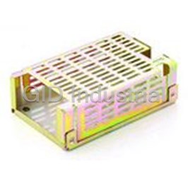
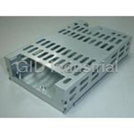
EOS POWER LFWLT60-CK

Description
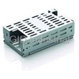
Metal Cover Kit Accessory
Part Number
LFWLT60-CK
Price
Request Quote
Manufacturer
EOS POWER
Lead Time
Request Quote
Category
Power » Power Accessories
Specifications
Manufacturer
EOS Power
Manufacturers Part #
LFWLT60-CK
Industry Aliases
LFWLT60-CK
Factory Pack Quantity
1
Datasheet

Extracted Text
60 Watt Industrial (WLT) Features l 50-65 W convection-cooled rating l Small 4 x 2 x 1.2 inches form factor l High efficiency > 85% l Single to triple outputs l EN55022-B, FCC Part 15 Level B l No Load Power < 0.3 W l Class 1 & Class 2 options l Cover kit accessory available Electrical Specifications AC Input 90-264 V, Universal 5 Input Frequency 47-400 Hz Input Current 120 VAC: 1.5 A max. 230 VAC: 0.75 A max. No Load Power < 0.3 W for single output models < 0.5 W for multi output models Inrush Current 120 VAC: 30 A max. 230 VAC: 60 A max. Leakage Current 120 VAC: < 500 µA 230 VAC: < 1000 µA 1 Efficiency 120 VAC: 85% typical 230 VAC: 85% typical Hold-up Time >10 ms @ 120 VAC typical Output Power 50-65 W Line Regulation +/-0.3% Load Regulation V1: +/-0.5%; V2 & V3: +/-5% Transient Response < 10%, 50% to 100% load change, 50/60 Hz, 50% duty cycle, 0.1 A/µs, recovery time < 5 ms Rise Time < 100 ms Set Point Tolerance V1: +/-3%; V2 & V3: +/-5% Output Adjustability V1: +/-10% Over Current Protection 130% typical above rating Over Voltage Protection 130% typical for V1 only Short Circuit Protection Short term, autorecovery Switching Frequency Approximately 67 kHz Operating Temperature -20 to 70°C, refer derating curve; -20 to 0°C, start-up is guaranteed Storage Temperature -40 to +85°C Relative Humidity 95% Rh, noncondensing Altitude Operating: 10,000 ft.; Nonoperating: 40,000 ft. MTBF 1.87m Hours, Telcordia -SR332-issue 3 Isolation Voltage Min. 4242 VDC between input to output Cooling Convection 13 4EM-17-174 39-DE60-46550-002 / E2 3 6 4 Model Number Voltage Max. Load Min. Load Ripple LFWLT60-1000 V1=5.2 V 10.0 A 0.0 A 1.25% LFWLT60-1001 V1=12 V 5.4 A 0.0 A 1% LFWLT60-1002 V1=15 V 4.33 A 0.0 A 1% LFWLT60-1003 V1=24 V 2.7 A 0.0 A 1% LFWLT60-1004 V1=48 V 1.35 A 0.0 A 1% LFWLT60-3000 V1=5.2 V, V2=12.5 V, V1=8.0 A, V2=3.0 A, V1=0.5 A, V2=0.1 A, V1=1.25%, V3=-12.5 V V3=0.5 A V3=0.0 A V2 & V3=1% LFWLT60-3001 V1=5.2 V, V2=23.8 V, V1=8.0 A, V2=1.5 A, V1=0.5 A, V2=0.1 A, V1, V2=1.25%, V3=-12.5 V V3=0.5 A V3=0.0 A V3=1% LFWLT60-3002 V1=5.2 V, V2=14.6 V, V1=8.0 A, V2=2.5 A, V1=0.5 A, V2=0.1 A, V1, V2=1.25%, V3=-16.2 V V3=0.5 A V3=0.0 A V3=1% LFWLT60-3003 V1=3.3 V, V2=5.2 V, V1=6.0 A, V2=3.0 A, V1=1.0 A, V2=0.1 A, V1=1.5%, V3=-12.8 V V3=0.5 A V3=0.0 A V2 & V3=1% LFWLT60-CK metal cover kit accessory Connectors J1 Pin 1 AC NEUTRAL Pin 2 AC LINE Spade Connector EARTH J2 Pin 1 V1 Pin 2 V1 Pin 3 RTN Pin 4 RTN Pin 5 V3 Pin 6 V2 J3 Pin 1 +V1 SENSE Pin 2 -V1 SENSE Notes 1. For WLT60-3003 efficiency is 75% typical. 2. Single output models deliver 65 W, except WLT60-1000 (50 W). Triple output models deliver 60 W, except WLT60-3003 (45 W). 3. Maximum current per output channel. Do not exceed total output power rating. 4. Ripple is peak to peak with 20 MHz bandwidth and 10 µF (Tantalum capacitor) in parallel with a 0.1 µF capacitor at rated line voltage and load ranges. 5. Safety approved 47-63 Hz. 6. Min Load specified to meet cross regulation. 7. Add -2 suffix to order Class 2 product. o 8. Specifications are for nominal input voltage, 25 C and max. load unless otherwise stated. 9. Derate output power linearly to 80% from 90 VAC to 80 VAC input. 10. Please refer mechnical outline drawing for height of component above and below PCB for - 1xxx & 3xxx. 11. When used in Cover Kit, de-rate output power to 70 % under all operating conditions 2 Innovations in Power 4EM-17-174 39-DE60-46550-002 / E2 Mechanical Specifications AC Input Connector (J1) Molex: 26-60-4030 or equivalent Mating: 09-50-3031; Pins: 08-50-0106 EARTH Molex: 19705-4301 Mating: 190030001 DC Output Connector (J2) Tyco: 640445-6 or equivalent Mating: 647402-6; Pins: 3-647409-1 Signal Connector (J3) Molex: 22-23-2021 or equivalent Mating: 22-01-2021 Dimensions 4.0 x 2.0 x 1.2 inches (101.6 x 50.8 x 30.48 mm) Weight 150 g EMC* Criteria Parameter Conditions/Description Pass Conducted Emissions EN55032-B, CISPR22-B, FCC PART15-B Pass Radiated Emissions EN 55032 B Class D Input Current Harmonics EN 61000-3-2 Pass Voltage Fluctuation and Flicker EN 61000-3-3 Level 3, Criterion A ESD Immunity EN 61000-4-2 Level 3, Criterion A Radiated Field Immunity EN 61000-4-3 Level 3, Criterion A Electrical Fast Transient Immunity EN 61000-4-4 Level 3, Criterion A Surge Immunity EN 61000-4-5 Level 3, Criterion A Conducted Immunity EN 61000-4-6 Level 3, Criterion A Magnetic Field Immunity EN 61000-4-8 Criterion A & B Voltage dips, interruptions EN 61000-4-11 Safety* CE Mark Complies with LVD Directive Approval Agency Nemko, UL, C-UL Safety Standard(s) IEC60950-1 (ed.2), EN60950-1, UL60950-1 (2nd Edition), CSA C22.2 No. 60950-1 (2nd Edition), Class 1 SELV *Safety File Number(s) Class I : Nemko: P15220205, NO88354 UL/C-UL: E150565 Class II : Nemko: P13216532, NO72728 UL/C-UL: E150565 15 4EM-17-174 39-DE60-46550-002 / E2 Derating Curve De-rate linearly from 100% at 50°C to 50% at 70°C Mechanical Drawing WLT60 - 1xxx Notes: In case the PCB is mounted in a metal enclosure, using metal hardware ensure the following 1. Stand off, used to mount PCB has OD of 5.4 mm max. 2. Screws, used to fix PCB on stand off, have head dia of 6.0 mm max. 3. Washer, if used, to have dia of 6.5 mm max. 4 Innovations in Power 4EM-17-174 39-DE60-46550-002 / E2 Mechanical Drawing WLT60 - 3xxx Notes: In case the PCB is mounted in a metal enclosure, using metal hardware ensure the following 1. Stand off, used to mount PCB has OD of 5.4 mm max. 2. Screws, used to fix PCB on stand off, have head dia of 6.0 mm max. 3. Washer, if used, to have dia of 6.5 mm max. 17 4EM-17-174 39-DE60-46550-002 / E2
Frequently asked questions
How does Electronics Finder differ from its competitors?

Is there a warranty for the LFWLT60-CK?
Which carrier will Electronics Finder use to ship my parts?
Can I buy parts from Electronics Finder if I am outside the USA?
Which payment methods does Electronics Finder accept?
Why buy from GID?

Quality
We are industry veterans who take pride in our work

Protection
Avoid the dangers of risky trading in the gray market

Access
Our network of suppliers is ready and at your disposal

Savings
Maintain legacy systems to prevent costly downtime

Speed
Time is of the essence, and we are respectful of yours
Related Products
Single, Dual and Triple Output 65W AC/DC Power Supplies ACC-GPS65-3
85W Single, Dual, Triple Quad Output AC/DC Power Supplies ACC-HPS85-3
Single, Dual And Triple Output 50W AC/DC Power Supplies ACC-SPS50-3
Cover Kit With Easy Assembly And Low Weight LFWLT100CK
Metal Cover Kit
Request a Quote

The quote request has been received
Close

Facing challenges or have inquiries? Feel free to contact us!
Call Us +1-469-283-2440
What they say about us
FANTASTIC RESOURCE
One of our top priorities is maintaining our business with precision, and we are constantly looking for affiliates that can help us achieve our goal. With the aid of GID Industrial, our obsolete product management has never been more efficient. They have been a great resource to our company, and have quickly become a go-to supplier on our list!
Bucher Emhart Glass
EXCELLENT SERVICE
With our strict fundamentals and high expectations, we were surprised when we came across GID Industrial and their competitive pricing. When we approached them with our issue, they were incredibly confident in being able to provide us with a seamless solution at the best price for us. GID Industrial quickly understood our needs and provided us with excellent service, as well as fully tested product to ensure what we received would be the right fit for our company.
Fuji
HARD TO FIND A BETTER PROVIDER
Our company provides services to aid in the manufacture of technological products, such as semiconductors and flat panel displays, and often searching for distributors of obsolete product we require can waste time and money. Finding GID Industrial proved to be a great asset to our company, with cost effective solutions and superior knowledge on all of their materials, it’d be hard to find a better provider of obsolete or hard to find products.
Applied Materials
CONSISTENTLY DELIVERS QUALITY SOLUTIONS
Over the years, the equipment used in our company becomes discontinued, but they’re still of great use to us and our customers. Once these products are no longer available through the manufacturer, finding a reliable, quick supplier is a necessity, and luckily for us, GID Industrial has provided the most trustworthy, quality solutions to our obsolete component needs.
Nidec Vamco
TERRIFIC RESOURCE
This company has been a terrific help to us (I work for Trican Well Service) in sourcing the Micron Ram Memory we needed for our Siemens computers. Great service! And great pricing! I know when the product is shipping and when it will arrive, all the way through the ordering process.
Trican Well Service
GO TO SOURCE
When I can't find an obsolete part, I first call GID and they'll come up with my parts every time. Great customer service and follow up as well. Scott emails me from time to time to touch base and see if we're having trouble finding something.....which is often with our 25 yr old equipment.
ConAgra Foods