

 Manufacturers
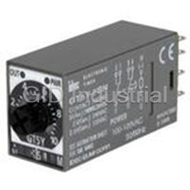
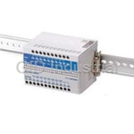
IDEC CORPORATION GT5Y-2SN3D12
Description
Electromechanical Relay DPDT 5A 12VDC Panel Mount
GT5Y-2SN3D12
Part Number
GT5Y-2SN3D12
Price
Request Quote
Manufacturer
IDEC CORPORATION
Lead Time
Request Quote
Category
Relays and I/O Modules » Relay Other
Specifications
Manufacturer
IDEC Corporation
Manufacturers Part #
GT5Y-2SN3D12
Industry Aliases
GT5Y-2SN3D12
Sub-Category
Other Relays
Factory Pack Quantity
1
Datasheet

Extracted Text
GT5Y Miniature Electronic Timers Four Selectable Time Ranges Delayed Output 4PDT/3A or DPDT/5A • Three operation modes: ON Delay, Interval ON, and Cycle • Repeat error: ±0.2% maximum • Miniature size • LED indicators for output and power • Complies with safety standards. UL/c-UL listed. EN compliant. Type List Package Quantity: 1 Time Ranges Time Range Time Ranges Code Scale Time Range Operation Operating Indication Contact Output (4 ranges Type No. Mode Voltage selectable) 1S 0 to 10 × 0.1 S 0.1 sec to 1 sec 10S 0 to 10 × 1 S 0.2 sec to 10 sec 1S/10S/1M/10M GT5Y-2SN1A100 1M 0 to 10 × 0.1 M 1.2 sec to 1 min 3S/30S/3M/30M 100 to 120V AC GT5Y-2SN3A100 10M 0 to 10 × 1 M 12 sec to 10 min 6S/60S/6M/60M GT5Y-2SN6A100 3S 0 to 3 × 1 S 0.1 sec to 3 sec 1S/10S/1M/10M GT5Y-2SN1A200 30S 0 to 3 × 10 S 0.5 sec to 30 sec 3S/30S/3M/30M 200 to 240V AC GT5Y-2SN3A200 3M 0 to 3 × 1 M 3 sec to 3 min 6S/60S/6M/60M GT5Y-2SN6A200 220V AC/ 30M 0 to 3 × 10 M 30 sec to 30 min DPDT 30V DC, 5A 1S/10S/1M/10M GT5Y-2SN1D12 6S 0 to 6 × 1 S 0.1 sec to 6 sec 3S/30S/3M/30M 12V DC GT5Y-2SN3D12 60S 0 to 6 × 10 S 1 sec to 60 sec 6S/60S/6M/60M GT5Y-2SN6D12 6M 0 to 6 × 1 M 6 sec to 6 min 60M 0 to 6 × 10 M 1 min to 60 min 1S/10S/1M/10M GT5Y-2SN1D24 3S/30S/3M/30M 24V DC GT5Y-2SN3D24 ON Delay 6S/60S/6M/60M GT5Y-2SN6D24 Contact Ratings 1S/10S/1M/10M GT5Y-4SN1A100 Type No. GT5Y-4 GT5Y-2 3S/30S/3M/30M 100 to 120V AC GT5Y-4SN3A100 Contact 4PDT DPDT Configuration 6S/60S/6M/60M GT5Y-4SN6A100 Resistive 220V AC, 3A 220V AC, 5A 1S/10S/1M/10M GT5Y-4SN1A200 Load 30V DC, 3A 30V DC, 5A 3S/30S/3M/30M 200 to 240V AC GT5Y-4SN3A200 220V AC/ 4PDT Inductive 30V DC, 3A 6S/60S/6M/60M GT5Y-4SN6A200 Load 220V AC, 0.8A 220V AC, 2A 3S/30S/3M/30M 12V DC GT5Y-4SN3D12 cosø=0.3 30V DC, 1.5A 30V DC, 2.5A L/R=7ms 1S/10S/1M/10M GT5Y-4SN1D24 Maximum Switching 3S/30S/3M/30M 24V DC GT5Y-4SN3D24 250V AC/125V DC 250V AC/125V DC Voltage 6S/60S/6M/60M GT5Y-4SN6D24 Maximum Switching 3A 5A (Note) 100 to 120V AC GT5Y-2SV1A100 Current 220V AC/ Maximum Switching DPDT 12V DC GT5Y-2SV1D12 1800 operations/hour 1800 operations/hour 30V DC, 5A Interval Frequency 1S/10S/1M/10M 24V DC GT5Y-2SV1D24 ON Resistive AC: 660VA AC: 1100VA 100 to 120V AC GT5Y-4SV1A100 220V AC/ Load DC: 90W DC: 150W 4PDT 30V DC, 3A 24V DC GT5Y-4SV1D24 Inductive 220V AC/ Load AC: 176VA AC: 440VA DPDT 100 to 120V AC GT5Y-2SF1A100 30V DC, 5A cosø= 0.3 DC: 45W DC: 75W Cycle 1S/10S/1M/10M L/R=7ms 200 to 240V AC GT5Y-4SF1A200 220V AC/ 4PDT 30V DC, 3A 24V DC GT5Y-4SF1D24 5V DC, 10mA 5V DC, 20mA (reference value) (reference value) Minimum Applicable Note: S and M of the time range indicate second, and minute respectively. Load 24V DC, 5mA 24V DC, 10mA (reference value) (reference value) Accessories External Protection Fuse 250V 3A Fuse 250V 5A Element Both SY4S-05C and SM2S-05C are UL recognized, CSA certified, and TÜV approved. Others are UL recognized and CSA certified, except for SY4S-05A and SM2S-05A. 200,000 operations 500,000 operations Electrical minimum minimum When ordering, specify the ordering Type No. (220V AC, 3A) (220V AC, 5A) Ordering Package Item Type No. Remarks 50 million operations 50 million operations Type No. Quantity Mechanical minimum minimum SY4S-05A SY4S-05A 1 For 4PDT contact Note: See Operating Temperature - Maximum Switching SY4S-05C SY4S-05C 1 For 4PDT contact Current Characteristics. SY4S-05D SY4S-05D 1 For 4PDT contact SY4S-05DF SY4S-05DF 1 For 4PDT contact Socket Operating Temperature - SM2S-05A SM2S-05A 1 For DPDT contact DIN Rail SM2S-05C SM2S-05C 1 For DPDT contact Maximum Switching Current Mount SM2S-05D SM2S-05D 1 For DPDT contact Socket Characteristics SM2S-05DF SM2S-05DF 1 For DPDT contact SFA- 10 sets Check the derating curve described below when SFA-202 For SY4S-05A, SM2S-05A (2 pcs/set) 202PN20 (20 pcs) Hold-Down mounting more than two GT5Y-2 timers and SM2S- Spring SFA- For SY4S-05D, SY4S-05DF, SFA-511 20 ∗ 05 sockets. 511PN20 SM2S-05D, SM2S-05DF Derating Curve SY4S-51 SY4S-51 1 For 4DPT contact, Solder Terminal Mounting SM2S-05A, C Direction Panel/ Sockets SY4S-61 SY4S-61 1 For 4DPT contact, PC Board Terminal 5A Socket PC SM2S-51 SM2S-51 1 For DPDT contact, Solder Terminal SM2S-05D, DF Board 2.5A Sockets SM2S-61 SM2S-61 1 For DPDT contact, PC Board Terminal Mount Socket Hold-Down SFA- 10 sets For SY4S-51, SY4S-61, SM2S-51, SFA-302 Spring 302PN20 (20 pcs) SM2S-61 (2 pcs/set) 40ºC 50ºC Operating Temperature 1086 Allowable Life Rated Load Contact Power Switching Current GT5Y Miniature Electronic Timers General Specifications Operation Charts and Internal Connections Flush Type GT5Y-oSN GT5Y-oSV GT5Y-oSF Operation Silhouette Item Operation Operation Type ON Delay Interval Cycle Mode Pollution Degree 2 (IEC60664-1) Control Set Time Overvoltage Category III (IEC60664-1) Terminal No. Units A200 200 to 240V AC (50/60Hz) 13-14 (POWER) Rated A100 100 to 120V AC (50/60Hz) Operational D24 24V DC Display Voltage 1-9, 3-11, 2-10, 4-12 (NC) D12 12V DC Lights ON Delay A200 170 to 264V AC (50/60Hz) 5-9, 7-11, 6-10, 8-12 (NO) A100 85 to 132V AC (50/60Hz) Voltage Display Range D24 21.6 to 26.4V DC Units D12 10.8 to 13.2V DC POWER Indicator Reset Voltage Rated Voltage × 20% minimum Operating Temperature -10 to +50°C (no freezing and condensation) Safety OUT Indicator Products Storage/Transporta- -30 to +80°C (no freezing and condensation) tion Temperature Set Time Terminal No. Operating Humidity 35 to 85% RH (no condensation) Terminal 13-14 (POWER) 0 to 2000m (operation) Altitude Blocks 0 to 3000m (transportation) Reset Time 100 ms maximum 1-9, 3-11, 2-10, 4-12 (NC) Repeat Error ±0.2%, ±20 ms maximum Interval Comm. Voltage Error ±0.5%, ±20 ms maximum ON Terminals 5-9, 7-11, 6-10, 8-12 (NO) Temperature Error ±3% maximum Setting Error ±10% maximum POWER Indicator Insulation Resistance 100 MΩ minimum (500V DC megger) AS-Interface Between power and output terminals: 2000V AC, 1 minute Dielectric Strength Between contacts of different poles: 2000V AC, 1 minute OUT Indicator Between contacts of the same pole: 1000V AC, 1 minute Relays & Set Time 10 to 55 Hz, amplitude 0.75 mm, 2 hours each in 3 direc- Vibration Resistance Timers Terminal No. TT tions 2 13-14 (POWER) Operating extremes: 98 m/s , Shock Resistance 2 Damage limits: 490 m/s , 3 shocks each in 6 directions Sockets Degree of Protection IP40 (timer), IP20 (socket) (IEC60529) 1-9, 3-11, 2-10, 4-12 (NC) A200 1.6 VA (200V AC/60Hz) Power Cycle A100 1.4 VA (100V AC/60Hz) Consumption 5-9, 7-11, 6-10, 8-12 (NO) Circuit D24 1.0W (approx.) Protectors D12 0.9W POWER Indicator Dimensions 27.5H × 21.0W × 58.6D mm Weight (approx.) 50g Power OUT Indicator Supplies Note: See Operating Temperature – Maximum Switching Current Charac- teristics. (Internal Connections) PLCs & • GT5Y-4 • GT5Y-4 •Electrical Life Curves SmartRelay 5000 5000 AC Load DC Load GT5Y-2 GT5Y-2 GT5Y-4 GT5Y-4 Operator 1000 1000 30V DC Resis. Load 110V AC Resis. Load 30V DC Induc. Load Interfaces 500 500 100V DC Resis. Load 220V AC Resis. Load 110V AC Induc. Load 100V DC Induc. Load 220V AC Induc. Load 100 100 Sensors 50 50 Control 10 10 0 12345 0 12345 Stations GT5Y-2 Load Current (A) Load Current (A) See page 1112 for SM2S-05A, SM2S-05C, SM2S-05D, SM2S-05DF. Dimensions Explosion Protection (When using DIN Rail Mount Socket) (When using DIN rail) BAA, BAP: 87.6 max. (Note 4) •GT5Y-4 83.6 max. (Note 3) See page 1113 for SY4S-05A, SY4S-05C, SY4S-05D, SY4S-05DF. References (When using DIN rail) BAA, BAP: 87.6 max. (Note 2) 83.6 max. (Note 1) Hold- DIN 21 6 52.6 6.4 Down Rail Spring 58.6 18.5 25 Hold- DIN 21 6 52.6 6.4 Down Rail Spring 58.6 Note 3: SM2S-05A: 83.6 max., SM2S-05C: 83.6 max., SM2S-05D: 88.6 18.5 max., SM2S-05DF: 88.6 max. 25 Note 4: SM2S-05A: 87.8 max., SM2S-05C: 87.8 max., SM2S-05DN: 92.8 max., SY4S-05DF: 92.8 max. Note 1: SY4S-05A: 83.6 max., SY4S-05C: 83.6 max., SY4S-05D: 88.6 max., SY4S-05DF: 88.6 max. Note 2: SY4S-05A: 87.8 max., SY4S-05C: 87.8 max., SY4S-05D: 92.8 max., SY4S-05DF: 92.8 max. 1087 27.5 Life (× 10,000 operations) Life (× 10,000 operations) 3 27.5 3 GT5P Miniature Electronic Timers Economic Efficiency Focused Delayed Output SPDT/5A • Three operation modes: ON Delay, Cycle, and One Shot • Repeat error: ±0.2% maximum • Complies with safety standards UL recognized, CSA certified, TÜV approved, EN compliant Type No. Package Quantity: 1 Time Ranges Operation Con- Time Operating Type No. Code Time Range Output Mode tact Range Voltage (Order No.) 1S 0.1 sec to 1 sec 3S GT5P-N3SA100 3S 0.1 sec to 3 sec 10S GT5P-N10SA100 6S 0.1 sec to 6 sec 30S GT5P-N30SA100 10S 0.2 sec to 10 sec 60S G 100 to 120V ACT5P-N60SA100 30S 0.5 sec to 30 sec 3M GT5P-N3MA100 60S 1 sec to 60 sec 6M GT5P-N6MA100 3M 3 sec to 3 min 10M GT5P-N10MA100 6M 6 sec to 6 min 1S GT5P-N1SA200 10M 10 sec to 10 min 6S GT5P-N6SA200 10S GT5P-N10SA200 30S GT5P-N30SA200 Contact Ratings 200 to 240V AC 60S GT5P-N60SA200 24V DC/ Contact Configuration SPDT ON Delay SPDT 120V AC, 5A 3M GT5P-N3MA200 Maximum Switching 250V AC, 150V DC 240V AC, 3A 6M GT5P-N6MA200 Voltage 10M GT5P-N10MA200 Maximum Switching 5A Current 1S GT5P-N1SAD24 Maximum Switching AC: 960VA 6S GT5P-N6SAD24 Power DC: 120W 10S GT5P-N10SAD24 24V AC/DC 60S GT5P-N60SAD24 120V AC / 24V DC, 5A Resistive Load 6M GT5P-N6MAD24 240V AC, 3A 10M GT5P-N10MAD24 Inductive Load 240V AC, 0.8A 10S GT5P-N10SD12 cosø = 0.3 - 0.4 120V AC, 1.4A L/R = 15 ms 24V DC, 1.7A 30S GT5P-N30SD12 12V DC 100,000 operations minimum 60S GT5P-N60SD12 Electrical (rated resistive load) 10M GT5P-N10MD12 20,000,000 operations 3S GT5P-F3SA100 Mechanical 100 to 120V AC minimum 10S GT5P-F10SA100 Minimum Applicable Load: 5V DC 10 mA (reference value) 3S GT5P-F3SA200 200 to 240V AC 24V DC/ 10S GT5P-F10SA200 Cycle SPDT 120V AC, 5A 3S GT5P-F3SAD24 240V AC, 3A 24V AC/DC 10S GT5P-F10SAD24 3S GT5P-F3SD12 12V DC 10S GT5P-F10SD12 3S 100 to 120V AC GT5P-P3SA100 3S GT5P-P3SA200 24V DC/ 200 to 240V AC One Shot SPDT 120V AC, 5A 10S GT5P-P10SA200 240V AC, 3A 3S GT5P-P3SAD24 24V AC/DC 10S GT5P-P10SAD24 Note: S and M of time range indicate second and minute respectively. Accessories Item Type No. Ordering Type No. Package Quantity Remarks SR2P-06A SR2P-06A 1 Socket SR2P-05A SR2P-05A 1 DIN Rail Mount SR2P-05C SR2P-05C 1 UL/CSA/TÜV Socket SFA-202 SFA-202PN20 10 sets (20 pcs) For SR2P-06A (2 pcs/set) Hold-Down Spring SFA-203 SFA-203PN20 10 sets (20 pcs) For SR2P-05A (2 pcs/set) w/Solder Terminals SR2P-511 SR2P-511 1 UL/CSA Panel Mount Socket w/Wire Wrap Terminals SR2P-70 SR2P-70 1 1088 Life Rated Load 240V AC cos ş = 0.4 120V AC cos ş = 0.4 24V DC τ = 15 ms 240V AC Resis. load 120V AC Resis. load 24V DC Resis. load GT5P Miniature Electronic Timers General Specifications Operation Charts and Internal Connections Flush Type GT5P-N GT5P-F GT5P-P Operation Silhouette Item Operation Operation Type ON Delay Cycle One Shot Mode Pollution Degree 2 (IEC60664-1) Control Set Time A200 200 to 240V AC (50/60Hz) Terminal No. Units Rated 2-7 (POWER) A100 100 to 120V AC (50/60Hz) Operational AD24 24V AC (50Hz/60Hz)/24V DC Voltage Display D12 12V DC 5-8 (NC) Lights A200 170 to 264V AC (50/60Hz) On Delay A100 85 to 132V AC (50/60Hz) Voltage 6-8 (NO) Range AD24 20.4 to 26.4V AC (50/60Hz)/21.6 to 26.4V DC Display Units D12 10.8 to 13.2V DC POWER Indicator Operating Temperature –10 to +50°C (no freezing) Storage/Transporta- Safety OUT Indicator –30 to +70°C (no freezing) tion Temperature Products Operating Humidity 35 to 85% RH (no condensation) Set Time Terminal No. TT 0 to 2000m (operation) Altitude 0 to 3000m (transportation) 2-7 (POWER) Terminal Blocks Reset Time 100 ms maximum Repeat Error ±0.2%, ±10 ms maximum 5-8 (NC) Voltage Error ±0.5%, ±20 ms maximum Comm. Cycle Temperature Error ±3% maximum Terminals 6-8 (NO) Setting Error ±10% maximum Insulation Resistance 100 MΩ minimum (500V DC megger) POWER Indicator AS-Interface Between power and output terminals: 2000V AC, 1 minute Dielectric Strength Between contacts of different poles: 2000V AC, 1 minute OUT Indicator Between contacts of the same pole: 750V AC, 1 minute Vibration Resistance 10 to 55Hz, amplitude 0.75 mm, 2 hours each in 3 directions Relays & Terminal No. 2 Timers Operating extremes: 98 m/s , Shock Resistance 2 13-14 (POWER) Damage limits: 490 m/s A200 3.9 VA (60Hz) 5.6 VA (60Hz) 50ms minimum Power Sockets A100 2.3 VA (60Hz) 2.9 VA (60Hz) 3-4 (Start Input) Consumption AD24 1.3 VA (60Hz)/0.5W 1.2 VA (60Hz)/0.5W (approx.) D12 0.6W 0.6W One Shot 5-8 (NC) Circuit Dimensions 36H × 29W × 81.5D mm Protectors Weight (approx.) 49g 6-8 (NO) • Electrical Life Curves Power POWER Indicator Supplies 100 70 50 OUT Indicator PLCs & 30 SmartRelay (Internal Connections) 20 ON Delay/Cycle One Shot 10 6 5 7(~)/( +) 6 5 7(~)/( +) Operator 7 Interfaces 4 5 3 2 3 Sensors 1 012345 8 2(~)/(-) 8 2(~)/(-) Load Current (A) Control Stations Dimensions (When using DIN Rail Mount Socket) Explosion • SR2P-05A • SR2P-06B Protection For SR2P-05C, see page 1109. References Note 1: SR2P-05C: 99.5 max. Note 2: SR2P-05C: 103.5 max. 1089 Life ( ×10,000 operations) GT5Y/GT5P Miniature Electronic Timers [Common] Dimensions / Mounting Hole Layout (for Panel/PC Board Mount Socket) 1. GT5Y-4 2. GT5Y-2 • Panel Mount Socket (SY4S-51) • Panel Mount Socket (SM2S-51) • PC Board Mount Socket (SY4S-61) • PC Board Mount Socket (SM2S-61) 3. GT5P • Solder Terminal (SR2P-511) • Wire Wrap Terminal (SR2P-70) Installation of Hold-Down Springs • DIN Rail Mount Socket • Panel/PC Board Mount Socket The SFA-302 Hold-Down Springs can be installed to the SY4S-51, SY4S-61, SM2S-51, and SM2S-61 sockets. Hold-down springs cannot be installed to SR2P-511 and SR2P-70 panel mount sockets. Note: Once installed into sockets, the hold-down springs cannot be removed. 1090 GT5Y/GT5P Miniature Electronic Timers [Common] ! Safety Precautions Flush Silhouette • Be sure to turn off power before mounting, removal, wiring, main- • Be sure to use wires to meet voltage and current requirements tenance and inspection. Otherwise, electric shock or fire could and tighten M3.5 terminal screws to a tightening torque of 1.0 to Control occur. 1.3 N•m. Be sure to solder the terminals correctly. Loose termi- Units • Be sure to use timers within rated specification values. Otherwise, nal screws or incomplete soldering may cause abnormal heat and electric shock or fire may occur. fire. Display Lights Instructions Display Time Range Setting Contact Protection Units The time range is calibrated at its maximum time scale, therefore Switching an inductive load generates a counter-electromotive force Safety it is desirable to use the timer at a setting as close to its maximum in the coil. The counter emf will cause arcing, which may shorten the Products time scale as possible for accurate time delay. For a more accurate contact life. Application of a protection circuit is recommended for time delay, adjust the control knob by measuring the operating time contact protection. with a watch before application. Terminal Blocks On the GT5Y timers, a desired time range can be selected using Rest Time the time range selectors on the side surface. Turn the multiplier and When turning power off after time-out, allow a rest time of 0.1 sec, time unit selectors using a flat screwdriver until they click. Comm. and during operation, 1 sec at least. Terminals Control knob Power AS-Interface Time range indication window Since DC types are designed to operate on DC power containing 10% or less ripple, insert a smoothing circuit when using a rectified Time range selector AC power to operate DC type timers. Relays & Timers Continuous Energizing Continuous energizing for a long period of time may damage the Sockets electrical characteristics of the timer because of internal heating. Use an additional relay to the output circuit and refrain from continu- ous energizing of the timer. Circuit Protectors Dielectric Strength Test Power When performing an insulation resistance or dielectric strength test Timing Accuracy Supplies on control panels containing timers, make sure that the dielectric Timing accuracies are calculated from the following formulas: strength of the timer is not exceeded. In case the dielectric strength PLCs & is exceeded, remove the timers from the panels. • Repeat Error SmartRelay 1 Max. measured value - Min. measured value = ± × × 100 (%) Operating Environment 2 Maximum scale value Operator • Temperature and Humidity Interfaces • Voltage Error Use the timer within the operating temperature and operating hu- Tv - Tr Tv: Average of measured values at voltage V midity ranges and prevent freezing and condensation. After stor- = ± × 100 (%) Tr Tr: Average of measured values at the raged voltage ing below the operation temperature, leave the timer at room tem- Sensors perature for a sufficient period of time before use. • Temperature Error • Environment Tt - T20 Tt: Average of measured values at t°C Control = ± × 100 (%) Prevent a corrosive gas such as sulfurous or ammonia gas, or- Stations T20 T20: Average of measured values at 20°C ganic solvents (alcohol, benzine, thinner, etc.), strong alkaline substances or strong acids from touching to the timer, and do not • Setting Error Explosion use the timer in such an environment. Keep the timer from water Average of measured values - Set value Protection = × 100 (%) splashes or steam. Maximum scale value • Vibration and Shock References Since excessive vibrations or shocks cause the output contacts Use of External Input (GT5P-P Only) to open, the timer should be used within the operating extremes 1. Do not apply voltage to external input terminals 3 and 4. Be sure of vibration and shock resistance. Use of hold-down springs is not to connect external inputs to other terminals because the recommended for secure mounting on sockets. internal circuit may be damaged. 2. Use reliable mechanical contacts capable of switching approxi- Others mately 22V DC, 1 mA to close input terminals 3 and 4. • Use a mechanical-contact switch or relay to supply power to the (Closed: 1 kΩ maximum, Open: 100 kΩ minimum) The input time. terminals should not be connected to a ground wire of other de- • When driving the timer using a solid-state output device such as vices. two-wire proximity switch, photoelectric switch or solid-state relay 3. Do not install input lines in parallel with high-voltage or motor directly, malfunction may be caused by a leakage current from the lines. Use shielded wires or separate conduit for input lines, and solid-state device. Be sure to check thoroughly before using. make the input lines as short as possible. • Since AC types (such as A100 and A200) comprise a capacitive load, the SSR dielectric strength should be two or more times as large as the power voltage when switching the timer power using Load Current an SSR. The rated current of the contact (or control output) should not be ex- • To make a sequence circuit by connecting timer and relay, check ceeded. Especially for inductive, capacitive, and incandescent lamp the timer operation sufficiently in consideration of the reset time loads, the inrush current as large as a few to several tens times the of the timer. rated current may cause welded contacts and other troubles. The amount of inrush current as well as steady-state current must be taken into consideration. 1091 GT5Y/GT5P Miniature Electronic Timers [Common] Installation/Removal of Hold-Down Springs Installation/Removal of Hold-Down Springs 1092
Frequently asked questions
How does Electronics Finder differ from its competitors?

Is there a warranty for the GT5Y-2SN3D12?
Which carrier will Electronics Finder use to ship my parts?
Can I buy parts from Electronics Finder if I am outside the USA?
Which payment methods does Electronics Finder accept?
Why buy from GID?

Quality
We are industry veterans who take pride in our work

Protection
Avoid the dangers of risky trading in the gray market

Access
Our network of suppliers is ready and at your disposal

Savings
Maintain legacy systems to prevent costly downtime

Speed
Time is of the essence, and we are respectful of yours
Related Products
Electromechanical Relay 220/240VAC 18.23KOhm 10A DPDT(27.5x21x41.6)mm Socket General Purpose Relay A...
Electromechanical Relay 100 to 240VAC 3A SPST-NO(42x75x77.5)mm DIN Rail Relay Barrier EB3C-R01A
Electromechanical Relay SPST-NO 3A 12VDC 1.2KOhm DIN Rail EB3C-R02A
Electromechanical Relay SPST-NO 3A 12VDC 1.2KOhm DIN Rail EB3C-R03A
Electromechanical Relay SPST-NO 3A 12VDC 1.2KOhm DIN Rail EB3C-R05A
Electromechanical Relay SPST-NO 3A 12VDC 1.2KOhm DIN Rail EB3C-R08A
Request a Quote

The quote request has been received
Close

Facing challenges or have inquiries? Feel free to contact us!
Call Us +1-469-283-2440
What they say about us
FANTASTIC RESOURCE
One of our top priorities is maintaining our business with precision, and we are constantly looking for affiliates that can help us achieve our goal. With the aid of GID Industrial, our obsolete product management has never been more efficient. They have been a great resource to our company, and have quickly become a go-to supplier on our list!
Bucher Emhart Glass
EXCELLENT SERVICE
With our strict fundamentals and high expectations, we were surprised when we came across GID Industrial and their competitive pricing. When we approached them with our issue, they were incredibly confident in being able to provide us with a seamless solution at the best price for us. GID Industrial quickly understood our needs and provided us with excellent service, as well as fully tested product to ensure what we received would be the right fit for our company.
Fuji
HARD TO FIND A BETTER PROVIDER
Our company provides services to aid in the manufacture of technological products, such as semiconductors and flat panel displays, and often searching for distributors of obsolete product we require can waste time and money. Finding GID Industrial proved to be a great asset to our company, with cost effective solutions and superior knowledge on all of their materials, it’d be hard to find a better provider of obsolete or hard to find products.
Applied Materials
CONSISTENTLY DELIVERS QUALITY SOLUTIONS
Over the years, the equipment used in our company becomes discontinued, but they’re still of great use to us and our customers. Once these products are no longer available through the manufacturer, finding a reliable, quick supplier is a necessity, and luckily for us, GID Industrial has provided the most trustworthy, quality solutions to our obsolete component needs.
Nidec Vamco
TERRIFIC RESOURCE
This company has been a terrific help to us (I work for Trican Well Service) in sourcing the Micron Ram Memory we needed for our Siemens computers. Great service! And great pricing! I know when the product is shipping and when it will arrive, all the way through the ordering process.
Trican Well Service
GO TO SOURCE
When I can't find an obsolete part, I first call GID and they'll come up with my parts every time. Great customer service and follow up as well. Scott emails me from time to time to touch base and see if we're having trouble finding something.....which is often with our 25 yr old equipment.
ConAgra Foods