

 Manufacturers
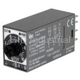
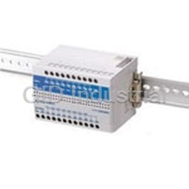
IDEC CORPORATION GT5Y-2SN6A100
Description
Electromechanical Relay DPDT 5A 100V to 120VAC Plug-In
GT5Y-2SN6A100
Part Number
GT5Y-2SN6A100
Price
Request Quote
Manufacturer
IDEC CORPORATION
Lead Time
Request Quote
Category
Relays and I/O Modules » Relay Other
Specifications
Manufacturer
IDEC Corporation
Manufacturers Part #
GT5Y-2SN6A100
Industry Aliases
GT5Y-2SN6A100
Sub-Category
Other Relays
Factory Pack Quantity
1
Datasheet

Extracted Text
GT5P Series Timers GT5P Series — ON Delay Timers Key features of the GT5P series include: • SPDT, 5A contacts • 8-pin, octal base •9 time ranges • Repeat error ±0.2% maximum • Control settings by hand or screwdriver • Power ON and timing out LED indicators • Uses the same sockets and hold down clips as IDEC’s RR2P 8-pin relays CSA CertiŢed UL Recognized File No. LR66809 File No. E55996 100 to 120V AC (50/60Hz) 200 to 240V AC (50/60Hz) Rated Operating Voltage 24V AC/DC 12V DC AC type: ±15% Voltage Tolerance DC type: ±10% (ripple 10% maximum) 120V AC/24V DC, 5A G Resistive load 240V AC, 3A Contact Rating 240V AC, 0.8A Inductive load 120V AC, 1.4A 24V DC, 1.7A 960VA AC Allowable Contact Power (resistive load) 120W DC Contact Form SPDT Voltage 250V AC, 150V DC Repeat Error ±0.2% ±10msec Voltage Error ±0.5% ±10msec ±3% maximum (over –10 to 50°C, Temperature Error reference temperature 20°C) Setting Error ±10% maximum When turning power off after time up: 0.1 sec maximum Reset Time When turning power off before time up: 1 sec maximum Insulation Resistance 100MΩ minimum 2000V AC, 1 minute (except between Dielectric Strength contacts of the same pole) Vibration Resistance 100N (approximate 10G) Operating extremes: Shock Resistance 100N (approximate 10G) Damage limits: 500N (approximate 50G) 100V AC type: 1.5VA (at 50Hz) GT5P Table of Contents Power Consumption 200V AC type: 1.6VA (at 50Hz) 24V DC type: 0.9W SpeciŢcations — G-58 Part Numbering List — G-59 Electrical Life 100,000 operations minimum (at rated load) Timing Diagrams / Schematics — G-60 Mechanical Life 20,000,000 operations minimum GT5P Accessories — G-61 Operating Temperature –10 to +50°C GT5P Dimensions — G-62 Operating Humidity 45 to 85% RH Timing Diagrams Overview — G-4 1.Inductive load (reference), cosθ =.3 to .4 or L/R=15msec. 2.Minimum applicable load: 5VDC/10mA (reference). G-58 www.idec.com USA: (800) 262-IDEC or (408) 747-0550, Canada: (888) 317-IDEC Timers Specifications Timers Timers GT5P Series Part Numbering List Mode of Rated Time Complete Contact Output Operation Voltage Range Part No. 1S — 3S GT5P-N3SA100 6S — 10S GT5P-N10SA100 100 to 30S GT5P-N30SA100 120V AC 60S GT5P-N60SA100 3M GT5P-N3MA100 6M GT5P-N6MA100 10M GT5P-N10MA100 1S GT5P-N1SA200 3S — 6S GT5P-N6SA200 10S GT5P-N10SA200 200 to 30S GT5P-N30SA200 240V AC 60S GT5P-N60SA200 3M GT5P-N3MA200 6M GT5P-N6MA200 G 24V DC/ 120V AC, 10M GT5P-N10MA200 5A ON-Delay SPDT 1S GT5P-N1SAD24 240V AC, 3A 3S — 6S GT5P-N6SAD24 10S GT5P-N10SAD24 24V AC/DC 30S — 60S GT5P-N60SAD24 3M — 6M GT5P-N6MAD24 10M GT5P-N10MAD24 1S — 3S — 6S — 10S GT5P-N10SD12 12V DC 30S GT5P-N30SD12 60S GT5P-N60SD12 3M — 6M — 10M GT5P-N10MD12 For sockets and accessories, see page G-61. www.idec.com USA: (800) 262-IDEC or (408) 747-0550, Canada: (888) 317-IDEC G-59 GT5P Series Timers Timing Diagram/Schematic/Electrical Life Curves SPDT 4 5 3 6 2 7 (-) (+) 8 Operation 1 Mode POWER Do not apply voltage to terminals 1, 3, and 4. Item Terminal No. Operation Set Time Power (Power) 2-7 (NC) 5-8 Delayed ON-Delay Contact (NO) 6-8 POWER Indicator OUT G Electrical Life Curves 100 70 50 30 20 24V DC Resistance Load 120V AC Resistance Load 10 7 240V AC Resistance Load 5 24V DC Induction Load 3 120V AC Induction Load 2 240V AC Induction Load 1 0 12345 Load Current (A) G-60 www.idec.com USA: (800) 262-IDEC or (408) 747-0550, Canada: (888) 317-IDEC Timers Life (x 10,000 operations) Timers Timers GT5P Series Accessories Mounting Accessories Part Numbers: Mounting Accessories and Sockets Applicable Hold-Down Springs Style Appearance Use with Timers Part No. Appearance Part No. 8-Pin Screw Terminal GT5P SR2P-05 (dual tier) SFA-203 8-Pin Fingersafe Socket GT5P SR2P-05C DIN Rail/ Surface Mounting Accessories 8-Pin Screw Terminal GT5P SR2P-06 SFA-202 DIN Mounting Rail — BNDN1000 Length 1000mm G Part Numbers: Mounting Accessories and Sockets Applicable Hold-Down Springs Mounting 8-Pin Solder Terminal SR2P-51 SFA-402 Accessories Installation of Hold-Down Springs DIN Rail Mount Socket Panel Mount Socket Insert the springs into the outer Hold-down Spring Insert the springs slots with the projections SFA-402 into the slots. facing inside. Insert 8-pin Socket SR2P-511 Socket SR3P-05 Hold-down Spring (sold separately) SFA-203 (use two springs) Socket SR2P-06 Hold-down Spring (sold separately) SFA-202 (use two springs) www.idec.com USA: (800) 262-IDEC or (408) 747-0550, Canada: (888) 317-IDEC G-61 GT5P Series Dimensions Timers Dimensions: GT5P Series " GT5P Timer, 8-Pin with SR2P-05 (When using DIN Rail) When using BAA/BAP: 102 maximum 98 maximum DIN Rail (BAA/BAP/BADA) Hold-down spring 29 7.5 61 13 16.5 74 20 28.5 GT5P Timer, 8-Pin with SR2P-06 (When using DIN Rail) When using BAA/BAP: 95.5 maximum 91.5 maximum Hold-down DIN Rail Spring 29 7.5 61 13 18 74 G 22 G-62 www.idec.com USA: (800) 262-IDEC or (408) 747-0550, Canada: (888) 317-IDEC Timers 36 36 33 ø25 1.7 3 52 31.7 1 60 Timers Timers GT5Y Series GT5Y Series — ON Delay Timers Key features of the GT5Y series include: • 4PDT, 3A or DPDT, 5A contacts •4 time ranges • Repeat error ±0.2% maximum • Control settings by hand or screwdriver • Power ON and timing out LED indicators • Uses the same sockets and hold-down clips as IDEC’s RY4S and RU series relays UL, c-uL Listed File No. E55996 GT5Y-2 GT5Y-4 100 to 120V AC (50/60Hz) 200 to 240V AC (50/60Hz) Rated Operating Voltage 24V DC 24V AC 12V DC Contact Form DPDT 4PDT 220V AC, 5A 220V AC, 3A G Resistive Load 30V DC, 5A 30V DC, 3A Rated Load 220V AC, 2A 220V AC, 0.8A Inductive Load 30V DC, 2.5A 30V DC, 1.5A 1100VA AC 660VA AC Resistive Load 150W DC 90W DC Allowable Contact Inductive Load 440VA AC 176VA AC Power Cos Ş = 0.3 75W DC 45W DC L/r = 7msec Allowable Voltage 250V AC, 125V DC Allowable Current 5A 3A Temperature Error ±3% maximum (over –10 to 50°C, reference temperature 20°C) Setting Error ±10% maximum When turning power off after time up: 0.1 second maximum Reset Time When turning power off before time up: 1 second maximum Insulation Resistance 100MΩ minimum Dielectric Strength 2,000V AC, 1 minute (except between contacts of the same pole) Vibration Resistance 100N (approximate 10G) Operating extremes: 100N (approximate 10G) Shock Resistance Damage limits: 500N (approximate 50G) 100V AC type: 1.5VA (at 50Hz) Power Consumption 200V AC type: 1.6VA (at 50Hz) 24V DC type: 0.9W 500,000 operations minimum 200,000 operations minimum Electrical Life (220V AC, 5A) (110V AC, 3A) GT5Y Table of Contents Mechanical Life 50,000,000 operations minimum 50,000,000 operations minimum Part Number List — G-64 Operating Temperature –10 to +50°C Timing Diagrams — G-65 Operating Humidity 45 to 85% RH GT5Y Accessories — G-66 GT5Y Dimensions — G-67 1. Minimum applicable load: GT5Y-2: 5V DC, 20mA (reference value); GT5Y-4: 5V DC, 10mA (reference value). 2. Inductive load: cosθ =.3, L/R=7msec. www.idec.com USA: (800) 262-IDEC or (408) 747-0550, Canada: (888) 317-IDEC G-63 Specifications GT5Y Series Timers Part Numbering List Mode of Rated Complete Contact Output Time Range Operation Voltage Part No. 1S/10S/1M/10M GT5Y-2SN1A100 100 to 120V AC 3S/30S/3M/30M GT5Y-2SN3A100 6S/60S/6M/60M GT5Y-2SN6A100 1S/10S/1M/10M GT5Y-2SN1A200 200 to 240V AC 3S/30S/3M/30M GT5Y-2SN3A200 6S/60S/6M/60M GT5Y-2SN6A200 1S/10S/1M/10M GT5Y-2SN1D12 220V AC/ DPDT 12V DC 3S/30S/3M/30M GT5Y-2SN3D12 30V DC, 5A 6S/60S/6M/60M GT5Y-2SN6D12 1S/10S/1M/10M GT5Y-2SN1D24 24V DC 3S/30S/3M/30M GT5Y-2SN3D24 6S/60S/6M/60M GT5Y-2SN6D24 1S/10S/1M/10M GT5Y-2SN1A24 24V AC 3S/30S/3M/30M GT5Y-2SN3A24 6S/60S/6M/60M GT5Y-2SN6A24 ON-Delay 1S/10S/1M/10M GT5Y-4SN1A100 100 to 120V AC 3S/30S/3M/30M GT5Y-4SN3A100 6S/60S/6M/60M GT5Y-4SN6A100 1S/10S/1M/10M GT5Y-4SN1A200 G 200 to 240V AC 3S/30S/3M/30M GT5Y-4SN3A200 6S/60S/6M/60M GT5Y-4SN6A200 1S/10S/1M/10M — 220V AC/ 4PDT 12V DC 3S/30S/3M/30M GT5Y-4SN3D12 30V DC, 3A 6S/60S/6M/60M — 1S/10S/1M/10M GT5Y-4SN1D24 24V DC 3S/30S/3M/30M GT5Y-4SN3D24 6S/60S/6M/60M GT5Y-4SN6D24 1S/10S/1M/10M GT5Y-4SN1A24 24V AC 3S/30S/3M/30M GT5Y-4SN3A24 6S/60S/6M/60M GT5Y-4SN6A24 1. For sockets and accessories, see page G-66. Timing Ranges Time Range Code Scale Time Range Indication 1S x 0.1 S 0.1 second to 1 second 10S x 1 S 0.2 second to 10 seconds 0 to 10 1M x 0.1 M 1.2 seconds to 1 minute 10M x 1 M 12 seconds to 10 minutes 3S x 1 S 0.1 second to 3 seconds 30S x 10 S 0.5 second to 30 seconds 0 to 3 3M x 1 M 3 seconds to 3 minutes 30M x 10 M 30 seconds to 30 minutes 6S x 1 S 0.1 second to 6 seconds 60S x 10 S 1 second to 60 seconds 0 to 6 6M x 1 M 6 seconds to 6 minutes 60M x 10 M 1 minute to 60 minutes G-64 www.idec.com USA: (800) 262-IDEC or (408) 747-0550, Canada: (888) 317-IDEC Timers Timers Timers GT5Y Series Timing Diagram/Schematics/Electrical Life Curves GT5Y-2 GT5Y-4 DPDT 4PDT 1 2 3 4 1 4 5 6 7 8 5 8 Internal Connections (bottom view) 9 10 11 12 9 12 (-) (+) (-) (+) 13 14 13 14 POWER POWER Item Terminal No. Operation Set Time Power (Power) 13-14 1-9, 2-10, (NC) 3-11, 4-12 Delayed Contact 5-9, 6-10, Operation Mode: (NO) 7-11, 8-12 ON-Delay POWER Indicator OUT G For an explanation of timing modes, see page E-4. Electrical Life Curves 5000 AC Load 110V AC Resistance Load 1000 GT5Y-2 220V AC Resistance Load GT5Y-4 500 110V AC Induction Load 100 220V AC Induction Load 50 Load Current (A) 12345 5000 DC Load 30V DC Resistance Load 1000 GT5Y-2 GT5Y-4 500 30V DC Induction Load 100V DC Resistance Load 100 100V DC Induction Load 50 12345 Load Current (A) www.idec.com USA: (800) 262-IDEC or (408) 747-0550, Canada: (888) 317-IDEC G-65 Life (x 10,000 operations) Life (x 10,000 operations) GT5Y Series Timers Accessories DIN Rail Mounting Accessories Part Numbers: DIN Rail/Surface Mount Sockets and Hold-Down Springs DIN Rail Mount Socket Applicable Hold-Down Springs Style Appearance Part No. Appearance Part No. 14-Blade Screw Terminal SY4S-05 SFA-202 14-Blade Screw Terminal (Ţngersafe) SY4S-05C DIN Mounting Rail Length 1000mm BNDN1000 G Panel Mounting Accessories Part Numbers: Panel Mount Socket and Hold-Down Springs Panel Mount Socket Applicable Hold-Down Springs Style Appearance Part No. Appearance Part No. 14-Blade Solder Terminal SY4S-51 SFA-302 PCB Mounting Accessories Part Numbers: PCB Mount Sockets with Applicable Hold-Down Springs PCB Mount Socket Applicable Hold-Down Springs Style Appearance Part No. Appearance Part No. 14 Blade, PCB Terminal SY4S-61 SFA-302 14 Blade, PCB Terminal SY4S-62 SY4S-02F1 G-66 www.idec.com USA: (800) 262-IDEC or (408) 747-0550, Canada: (888) 317-IDEC Timers Timers Timers GT5Y Series Dimensions GT5Y Timer, Blade with SY4S-05 28.5 when When using DIN Rail using BAA 30 When using BAA/BAP: 87.6 maximum 83.6 maximum 6 18 Terminal DIN Rail (BAA) Arrangement M3 Screw 8 7 6 5 2-ø4.2 Mounting Hole 4 3 2 1 (M4 screw hole) Hold- DIN 21 6 52.6 6.4 down Rail 26 Spring 58.6 18.5 14 13 4max. 4.8min. 12 11 10 25 9 ø3.2min. ( ) TOP VIEW 18.5 5.9max. 26 25 G www.idec.com USA: (800) 262-IDEC or (408) 747-0550, Canada: (888) 317-IDEC G-67 27.5 3 62 3 62 0.7 4.2 45 General Instructions Timers General Instructions for All Timer Series Load Current Time Setting With inductive, capacitive, and incandescent lamp loads, inrush current more The time range is calibrated at its maximum time scale; so it is desirable to than 10 times the rated current may cause welded contacts and other undes- use the timer at a setting as close to its maximum time scale as possible. For ired effects. The inrush current and steady-state current must be taken into a more accurate time delay, adjust the control knob by measuring the operat- consideration when specifying a timer. ing time with a watch before application. Input Contacts Contact Protection Use mechanical contact switch or relay to supply power to the timer. When Switching an inductive load generates a counter-electromotive force (back driving the timer with a solid-state output device (such as a two-wire proxim- EMF) in the coil. The back EMF will cause arcing, which may shorten the con- ity switch, photoelectric switch, or solid-state relay), malfunction may be tact life and cause imperfect contact. Application of a protection circuit is caused by leakage current from the solid-state device. Since AC types com- recommended to safeguard the contacts. prise a capacitive load, the SSR dielectric strength should be two or more times the power voltage when switching the timer power using an SSR. Temperature and Humidity Use the timer within the operating temperature and operating humidity Generally, it is desirable to use mechanical contacts whenever possible to ranges and prevent freezing or condensation. After the timer has been stored apply power to a timer or its signal inputs. When using solid state devices, be below its operating temperature, leave the timer at room temperature for a cautious of inrushes and back-EMF that may exceed the ratings on such sufŢcient period of time to allow it to return to operating temperatures before devices. Some timers are specially designed so that signal inputs switch at a use. lower voltage than is used to power the timer (models designated as “B" type). Environment Avoid contact between the timer and sulfurous or ammonia gases, organic solvents (alcohol, benzine, thinner, etc.), strong alkaline substances, or strong acids. Do not use the timer in an environment where such substances are prevalent. Do not allow water to run or splash on the timer. Vibration and Shock Excessive vibration or shocks can cause the output contacts to bounce, the timer should be used only within the operating extremes for vibration and shock resis- tance. In applications with signiŢcant vibration or shock, use of hold down springs or clips is recommended to secure a timer to its socket. G Timing Accuracy Formulas Timing accuracies are calculated from the following formulas: Repeat Error = ± 1 x Maximum Measured Value – Minimum Measured Value x 100% 2 Maximum Scale Value Voltage Error = ± Tv - Tr x 100% Tr T : Average of measured values at voltage V v T Average of measured values at the rated voltage r: Temperature Error = ± Tt - T20 x 100% T20 T : Average of measured values at °C t T : Average of measured values at 20°C 20 Setting Error = ± Average of Measured Values - Set Value x 100% Maximum Scale Value G-68 www.idec.com USA: (800) 262-IDEC or (408) 747-0550, Canada: (888) 317-IDEC Timers
Frequently asked questions
How does Electronics Finder differ from its competitors?

Is there a warranty for the GT5Y-2SN6A100?
Which carrier will Electronics Finder use to ship my parts?
Can I buy parts from Electronics Finder if I am outside the USA?
Which payment methods does Electronics Finder accept?
Why buy from GID?

Quality
We are industry veterans who take pride in our work

Protection
Avoid the dangers of risky trading in the gray market

Access
Our network of suppliers is ready and at your disposal

Savings
Maintain legacy systems to prevent costly downtime

Speed
Time is of the essence, and we are respectful of yours
Related Products
Electromechanical Relay 220/240VAC 18.23KOhm 10A DPDT(27.5x21x41.6)mm Socket General Purpose Relay A...
Electromechanical Relay 100 to 240VAC 3A SPST-NO(42x75x77.5)mm DIN Rail Relay Barrier EB3C-R01A
Electromechanical Relay SPST-NO 3A 12VDC 1.2KOhm DIN Rail EB3C-R02A
Electromechanical Relay SPST-NO 3A 12VDC 1.2KOhm DIN Rail EB3C-R03A
Electromechanical Relay SPST-NO 3A 12VDC 1.2KOhm DIN Rail EB3C-R05A
Electromechanical Relay SPST-NO 3A 12VDC 1.2KOhm DIN Rail EB3C-R08A
Request a Quote

The quote request has been received
Close

Facing challenges or have inquiries? Feel free to contact us!
Call Us +1-469-283-2440
What they say about us
FANTASTIC RESOURCE
One of our top priorities is maintaining our business with precision, and we are constantly looking for affiliates that can help us achieve our goal. With the aid of GID Industrial, our obsolete product management has never been more efficient. They have been a great resource to our company, and have quickly become a go-to supplier on our list!
Bucher Emhart Glass
EXCELLENT SERVICE
With our strict fundamentals and high expectations, we were surprised when we came across GID Industrial and their competitive pricing. When we approached them with our issue, they were incredibly confident in being able to provide us with a seamless solution at the best price for us. GID Industrial quickly understood our needs and provided us with excellent service, as well as fully tested product to ensure what we received would be the right fit for our company.
Fuji
HARD TO FIND A BETTER PROVIDER
Our company provides services to aid in the manufacture of technological products, such as semiconductors and flat panel displays, and often searching for distributors of obsolete product we require can waste time and money. Finding GID Industrial proved to be a great asset to our company, with cost effective solutions and superior knowledge on all of their materials, it’d be hard to find a better provider of obsolete or hard to find products.
Applied Materials
CONSISTENTLY DELIVERS QUALITY SOLUTIONS
Over the years, the equipment used in our company becomes discontinued, but they’re still of great use to us and our customers. Once these products are no longer available through the manufacturer, finding a reliable, quick supplier is a necessity, and luckily for us, GID Industrial has provided the most trustworthy, quality solutions to our obsolete component needs.
Nidec Vamco
TERRIFIC RESOURCE
This company has been a terrific help to us (I work for Trican Well Service) in sourcing the Micron Ram Memory we needed for our Siemens computers. Great service! And great pricing! I know when the product is shipping and when it will arrive, all the way through the ordering process.
Trican Well Service
GO TO SOURCE
When I can't find an obsolete part, I first call GID and they'll come up with my parts every time. Great customer service and follow up as well. Scott emails me from time to time to touch base and see if we're having trouble finding something.....which is often with our 25 yr old equipment.
ConAgra Foods