

 Manufacturers
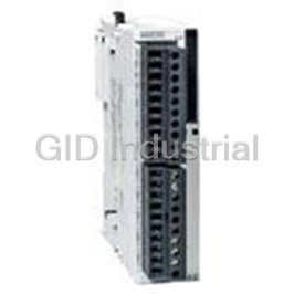
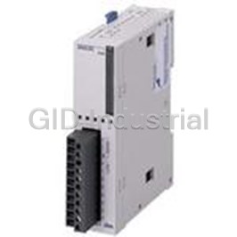
IDEC CORPORATION SX5L-SBM16K1

Description
I/O Module Relays I/O Module 24VDC 6mA 500VAC DIN Rail
SX5L-SBM16K1
Part Number
SX5L-SBM16K1
Price
Request Quote
Manufacturer
IDEC CORPORATION
Lead Time
Request Quote
Category
Relays and I/O Modules » I/O Module
Specifications
Manufacturer
IDEC Corporation
Manufacturers Part #
SX5L-SBM16K1
Lead Time
4 Week Lead Time
Industry Aliases
SX5L-SBM16K1
Sub-Category
I/O Modules
Factory Pack Quantity
1
Datasheet

Extracted Text
Communication & Networking PLCs Operator Interfaces Automation Software Power Supplies Sensors LONWORKS® I/O Modules Communication & Networking LONWORKS® I/O Modules ® LONWORKS I/O modules for building automation Illumination Alarm • ON/OFF Control • Fire, earthquake,gas leakage alarm LONWORKS is a leading open solution for building and home automation, • Area illumination industrial, transportation and public utility control networks. IDEC provides a variety of compact LONWORKS communication terminals containing SNVTs to enable cost-effective design and implementation of multi- vendor control systems. LON, LONWORKS, LonMaker, LONMARK, 3120 and Echelon are registered trademarks of Echelon, USA. Terminal Block Style I/O Modules Open Networks for Building Automation Standard Network Variable Type (SNVT) • Removable fi nger-safe spring-up terminal blocks protect against electric shocks and save wiring time. HVAC Security • Start/stop heaters and air-conditioners • Sensor signal transmission • Compact housing for all modules: 75H x 132W x 48D mm • 12 different modules designed for general purpose digital control • I/O signals for specialized applications. • Digital I/O module is also available for start/stop control with 8 inputs and 8 outputs. • Analog input and Pt100Ω input modules are ideal for air-conditioning and temperature control. • Pulse input module can count input pulse signals. • Lighting control module is used for illumination control of fl uorescent and incandescent lamps. • Standard confi guration property type (SCPT) allows for adjusting communi- Elevator Access Control cation traffi c. • ON/OFF control • ID card scanner data transmission • LONMARK compliant. • Status/alarm signal transmission Energy Control Building Control • Data collection of utility charges • Control and monitoring from a for each fl oor central control room ® LONWORKS is the registered trademark of Echelon Corporation. USA: 800-262-IDEC Canada: 888-317-IDEC 295 LONWORKS® I/O Modules Communication & Networking Part Numbers Module Name Voltage I/O Features Part Number Digital Input 24V DC 16-point source/sink input SX5L-SBN16B1 16-point transistor sink output SX5L-SBT16K1 Digital Output 24V DC 16-point transistor source output SX5L-SBT16S1 • 16 inputs, 16 outputs, or 8 in/8 out 8-point transistor source input • Start/stop control module is also available with 8 inputs SX5L-SBM16K1 8-point transistor sink output and 8 outputs. • Output and I/O modules contain virtual I/O functional 8-point transistor source input SX5L-SBM16K2 blocks which can be used for Boolean operation (AND, 8-point transistor sink output (start/stop control) OR, NOT) on bit data and for enabling/disabling output Digital I/O 24V DC 8-point transistor sink input network variables. SX5L-SBM16S1 8-point transistor source output 8-point transistor sink input SX5L-SBM16S2 8-point transistor source output (start/stop control) • 4 analog input channels for 1 to 5V and 4 to 20mA DC inputs Analog Input 24V AC/DC 4-point, 1 to 5V, 4 to 20mA SX5L-SBAN041 • Network variable models can be changed to meet units of analog input data. Analog Output 24V AC/DC 4-point, 4 to 20mA SX5L-SBAT04X1 4-point, 3-wire Pt100Ω resistance thermometer, 0 to 50°C • 4 input channels for room temperature control SX5L-SBPT04X1 (0 to +50°C) Pt100Ω Input 24V AC/DC • 4 input channels for water temperature control 4-point, 3-wire Pt100Ω resistance thermometer, –20 to +80°C SX5L-SBPT04Y1 (–20 to +80°C) • 8 inputs for counting input pulses (minimum pulse width 50ms) Pulse Input 24V AC/DC 8-point pulse input • Maintains count of current values when power is SX5L-SBCN081 interrupted. • Counter current values can be changed by input variable. • Controls 8 remote control relays for fl uorescent and incandescent lamps. Lighting Control 24V AC 8-point, remote-control relay control SX5L-SBRR081 • Remote-control relays on existing illumination systems can also be controlled. Accessories Applicable Terminal Blocks/Insertion Pin Positions Name Part Number SX5L Module Terminal Block Terminal Block Insertion Part Number Position Part No. Pin Positions Terminal Block 1 SX9Z-SS1 Upper SX9Z-SS10 B D F H Terminal Block 2 SX9Z-SS2 SX5L-SBN16B1 Lower SX9Z-SS2 A C F H Terminal Block 3 SX9Z-SS3 Upper SX9Z-SS1 B C E G SX5L-SBT16K1 Terminal Block 7 SX9Z-SS7 SX5L-SBT16S1 Lower SX9Z-SS2 A D F H Terminal Block 9 SX9Z-SS9 SX5L-SBM16K1 Terminal Block 10 SX9Z-SS10 Upper SX9Z-SS1 B C F H SX5L-SBM16K2 Terminal Block 11 SX9Z-SS11 SX5L-SBM16S1 Lower SX9Z-SS3 A D E G SX5L-SBM16S2 Terminal Block 12 SX9Z-SS12 Upper SX9Z-SS12 A D E H Terminal Block 13 SX9Z-SS13 SX5L-SBAN041 Lower SX9Z-SS9 B C F G Terminal Block 14 SX9Z-SS14 Upper SX9Z-SS13 B D E H SX5L-SBPT04X1 Terminal Block 16 SX9Z-SS16 SX5L-SBPT04Y1 Lower SX9Z-SS14 A C F G BAA1000 DIN Rail (1m long) Upper SX9Z-SS11 A C E H BNDN1000 SX5L-SBCN081 Lower SX9Z-SS7 B C E H End Stop BNL5 1 Upper SX9Z-SS11 B D F G Network Interface Connector SX9Z-CN23 SX5L-SBRR081 Lower SX9Z-SS7 A D F G Ring BPJ-26B 2 Jumper Spade BPJ-26FB 1. Supplied with two mounting screws. 2. For connecting terminals of an unused channel on analog input and Pt100Ω input modules. 296 www.idec.com Communication & Networking Sensors Power Supplies Automation Software Operator Interfaces PLCs Communication & Networking PLCs Operator Interfaces Automation Software Power Supplies Sensors LONWORKS® I/O Modules Communication & Networking Specifi cations General Specifi cations Models SX5L-SBN16B1 SX5L-SBT16*1 SX5L-SBM16** SX5L-SBAN041 SX5L-SBPT04*1 SX5L-SBCN081 SX5L-SBRR081 Voltage 24V DC 24V AC (50/60Hz) / 24V DC 24V AC (50/60Hz) 21.6 to 26.4V AC Voltage Range 21.6 to 26.4V DC (including 5% ripple) 21.6 to 26.4V AC/DC (including 5% ripple) (including 5% ripple) 1.8 VA (24V AC) (not 2.0 VA (24V AC) including power con- Power Consumption 1.0W (24V DC) 1.2W (24V DC) 3.0 VA (24V AC), 1.8W (24V DC) 1.0W (24V DC) sumption by remote- control relays) Inrush Current ≥ 3A (24V DC) ≥ 15A (24V AC/DC) ≥ 15A (24V AC) Allowable Momentary ≥ 10ms (at the rated power voltage) Power Interruption Dielectric Strength 1,000V AC, 1 minute between power and FG terminals Insulation Resistance 100 MΩ minimum between power and FG terminals (500V DC megger) Operating Temperature 0 to 55°C (no freezing) Operating Humidity 30 to 90% RH (non-condensing) Storage Temperature –20 to +75°C (no freezing) Storage Humidity 30 to 90% RH (non-condensing) Pollution Degree 2 (IEC60664) Corrosion Immunity Atmosphere free from corrosive gases Altitude Operation: 0 to 2,000m, Transport: 0 to 3,000m 2 10 to 57Hz amplitude 0.075mm, 57 to 150Hz acceleration 9.8 m/s (1G) Vibration Resistance 2 hours per axis on each of three mutually perpendicular axes 2 Shock Resistance 294 m/s (30G), 11-ms sinusoidal half-wave pulse Mounting DIN rail, direct panel mounting (M4 mounting screws) Weight (approx.) 240g 250g Communication Specifi cations Communication Status LEDs ® Communication System LON system Name Color Description Transceiver FTT-10A PWR Green Remains on while power is supplied. Connection Topology Bus topology, free topology Goes on when, after powerup, self-diagnosis has completed and RUN Green application starts. Transmission Speed 78 kbps Goes on when, after application has started, output network vari- 1,400m (when using only FTT-10A transceivers) Bus Topology ERR Red able update failed. (Level 4, 22AWG cable) Transmission Goes off when output network variable is updated successfully. Distance 500m total, 400m between nodes Free Topology RES — Reserved (does not go on) (Level 4, 22AWG cable) Goes on when application program is not confi gured yet. Neuron Chip TMPN3120FE5M (Toshiba) SER Yellow Flashes when network information is not confi gured yet. Removable Finger-safe Terminal Block Network Interface Connector Rated Insulation Voltage 250V Receptacle in Connector Module Housing for Cable Terminal Screw M3 (on 7.62-mm centers) Phoenix Contact Part Numbers MSTBV2.5/2-GF-5.08 FKC2.5/2-STF-5.08 No. of Poles 10 poles IDEC Part Numbers — SX9Z-CN23 Rated Thermal Current 7A Insertion/Removal Durability 100 times Insertion/Removal Durability 100 times USA: 800-262-IDEC Canada: 888-317-IDEC 297 LONWORKS® I/O Modules Communication & Networking Dimensions Mounting Hole Layout 48 100±0.5 33±0.5 132 19 5.0 2-M4 or ø4.5 holes All dimensions in mm. Features Spring-up Terminals Removable Terminal Block The spring-loaded screws make installation as easy as pushing down and turn- The terminal block can be removed simply by squeezing both latches on the top ing with a screwdriver. Installation time is cut in half since the screws do not of the block inward to unlock the block from the socket. To reattach the terminal need to be backed out to install wiring. Screw terminals accept bare wire, ring or block, place the block in the socket with the latches opened and press the block fork connectors. until it snaps. Wiring can be done with the terminal block removed, so installation in tight spaces is easy. Finger-safe Terminal Cover After connecting wires, screw terminals are fi nger-safe. Keyed Terminal Blocks Insertion pins are positioned on the base of the terminal block and inside the socket to prevent insertion of an incorrect terminal block into the socket. The pins are keyed to ensure correct terminal blocks and sockets, and to prevent swapping of upper and lower terminal blocks. Insertion pin 298 www.idec.com Communication & Networking Sensors Power Supplies Automation Software Operator Interfaces PLCs 39 3.6 75 50 min. 60±0.5 7.5 Communication & Networking PLCs Operator Interfaces Automation Software Power Supplies Sensors LONWORKS® I/O Modules Communication & Networking System Setup Examples Bus Topology Quantity of Nodes (FTT-10A Transceiver Nodes) Nodes are connected to one trunk line. The trunk line can be extended up to A maximum of 64 nodes can be connected to one channel. When connecting 1,400 meters. more than 64 nodes, a router or repeater is needed. Terminators are needed at both ends of the network. A router is regarded as one node. Consequently, when using one router, the maximum number of nodes connected to one channel will reduce to 63. Channel 1 Node Node Node Node Terminator Terminator Terminator Terminator Node Node Router Channel 2 Node Free Topology The network can also be connected in a star, loop, bus, or combination of these Node confi gurations. The network can be expanded and modifi ed. Terminator Node One terminator is needed on the network and it can be located anywhere. Terminator Node Node Maximum total cable length: 500 meters Maximum distance between nodes: 400 meters USA: 800-262-IDEC Canada: 888-317-IDEC 299 LONWORKS® I/O Modules Communication & Networking Parts Description Software Common Specifi cations Removable Terminal Block (Upper) Network Variables I/O LEDs FG Terminal and A network variable is data that a particular device application program expects Panel Mounting Hole (M4) to get from another device on a network (an input network variable) or expects to make available to other devices on a network (an output network variable). SERVICE Examples are temperature, switch values and actuator position settings. REQUEST (Pushbutton) SERVICE REQUEST I/O Name Type LON Input Network Variable nviRequest SNVT_obj_request Output Network Variable nvoStatus SNVT_obj_status Communication Status LEDs When receiving nviRequest, the SX5L sends out nvoStatus in reply. This func- tionality makes it possible for the network to confi rm that the responding node is Removable Terminal Block (Lower) Network in an on-line status. DIN Rail Mounting Clamp Interface Connector Neuron ID Number and Barcode Confi guration Property (Code 39: Narrow bar 0.1 mm) Confi guration property is a data value used to determine initial values and Panel Mounting Hole (M4) parameters, such as maximum values, minimum values and time, for a particular LONWORKS device. Name Type nciPwrup SCPTpwrUpDelay Confi guration Property nciMaxStsSendT SCPTmaxSndT The SX5L sends output network variable nvoStatus to the network within 3 seconds after powerup. The delay depends on a random number based on the Neuron ID and differs on each node. The sending time can be delayed by changing the nciPwrup value. At system DIN Rail Mounting Clamp startup, if the SX5L sends nvoStatus before the addressee device is ready to receive communication, set the nciPwrup to a larger value. Network Interface Connector The network interface connector features spring-clamp terminals. Push in the The preset value for nciPwrup can be between 0 and 60 seconds (0.1-sec incre- orange pin to open the cable hole using a fl at screwdriver and insert a cable into ments). The sending time is determined by the sum of the nciPwrup value and a the cable hole. LONWORKS network cables can be connected to the two terminals random number. in either polarity. After the fi rst transmission of output network variable nvoStatus, the SX5L sends nvoStatus repeatedly at intervals designated by nciMaxStsSendT. When the nciMaxStsSendT value is 0, heartbeat transmission is disabled. The confi guration type of nciMaxStsSendT is SNVT_elapsed_tm (day, hour, minute, second, millisecond). When a value over 12 hours is set, the interval is designated as 12 hours 00 minutes 00 seconds. Network Management Tool Orange Pin When setting up a LonWorks network system using SX5L modules, a network management tool is needed, such as LonBuilder or LONMAKER. 300 www.idec.com Communication & Networking Sensors Power Supplies Automation Software Operator Interfaces PLCs Communication & Networking PLCs Operator Interfaces Automation Software Power Supplies Sensors LONWORKS® I/O Modules Communication & Networking Digital Input Module SX5L-SBN16B1 Wiring Diagram and Internal Circuit Negative Common Wiring – – – OUT + + + 3-wire 2-wire NPN sensor sensor COM COM07 1 2 3 4 5 6 • 16 digital inputs can be connected with either negative or positive common wiring. Network Interface • Used for transmitting digital signals to the network such as alarm signals from local sensors. POWER + – 8 9 10 11 12 13 14 15 General Specifi cations + – Fuse Voltage 24V DC + – Voltage Range 21.6 to 26.4V DC (including 5% ripple) 24V DC Power Consumption 1.0W (24V DC) Positive Common Wiring Inrush Current 3A maximum (24V DC) + + OUT + – Weight (approx.) 240g – – 3-wire 2-wire PNP sensor sensor Digital Input Specifi cations COM COM07 1 2 3 4 5 6 Input Points 16 points No-voltage input (DC 2-wire sensor, 3-wire sensor, Input no-voltage contact) Network Input Voltage 24V DC Interface Input Voltage Range 0 to 26.4V DC Input Impedance Approx. 4.0 kΩ POWER + – 8 9 10 11 12 13 14 15 Input Current 6mA/point (24V DC) No. of Common Circuits 1 + – Fuse Input Common Polarity Positive and Negative common compatible + – 24V DC Input Delay Time 250 ms Terminal Arrangement Input Turn ON Voltage 15V min. (between input and COM terminals) Upper Terminal Block (SX9Z-SS10) Input Turn OFF Voltage 5V max. (between input and COM terminals) Marking COM COM 0 1 2 Input OFF Current 1mA maximum Name Input Common Input 0 Input 1 Input 2 Isolation from Power Photocoupler isolation Line Marking 34567 500V AC, 1 minute between input and FG or Dielectric Strength power terminals Name Input 3 Input 4 Input 5 Input 6 Input 7 100 MΩ minimum between input and FG or power Insulation Resistance terminals (500V DC megger) Network Variables Output Network Variable Lower Terminal Block (SX9Z-SS2) Name Type Description Marking POWER+ POWER– 8 9 10 nvoDI[0] to [15] SNVT_switch Correspond to inputs 0 through 15 Power Terminals Name Input 8 Input 9 Input 10 24V DC 0V Confi guration Property Name Type Description Marking 11 12 13 14 15 nciMaxStsSendT1 SCPTmaxSndT nvoDI[0] to [15] heartbeat transmission interval [0] to [15] Name Input 11 Input 12 Input 13 Input 14 Input 15 +– USA: 800-262-IDEC Canada: 888-317-IDEC 301 LONWORKS® I/O Modules Communication & Networking Digital Output Modules SX5L-SBT16K1/SX5L-SBT16S1 Wiring Diagram and Internal Circuit SX5L-SBT16K1: Positive Common Wiring + – + –07 1 2 3 4 5 6 • 16 transistor outputs for either negative or positive common wiring. Network Interface • Each module contains 6 virtual I/O functional blocks with 2 input and 2 output network variables. POWER + – 8 9 10 11 12 13 14 15 General Specifi cations Voltage 24V DC + – Fuse + – Voltage Range 21.6 to 26.4V DC (including 5% ripple) 24V DC Power Consumption 1.2W (24V DC) SX5L-SBT16S1: Negative Common Wiring Inrush Current 3A maximum (24V DC) – Weight (approx.) 240g + Transistor Output Specifi cations Models SX5L-SBT16K1 SX5L-SBT16S1 + –07 1 2 3 4 5 6 Output Points 16 points N-MOS open drain P-MOS open drain Output (NPN transistor output) (PNP transistor output) Network Interface Load Voltage 24V DC Load Voltage Range 21.6 to 26.4V DC POWER Maximum Load Current 500mA per point, 6A per common line + – 8 9 10 11 12 13 14 15 Output Common Polarity Positive common Negative common + – Fuse 0.8V maximum (voltage 0.8V maximum (voltage + – Voltage Drop between power – terminal between power + terminal 24V DC (ON Voltage) and output terminals when and output terminals Terminal Arrangement output is on) when output is on) Upper Terminal Block (SX9Z-SS1) Leakage Current 1mA maximum Marking + – 0 1 2 Isolation from Power Photocoupler isolation Load Power Line Name Output 0 Output 1 Output 2 24V DC 0V 500V AC, 1 minute between output and FG or power Dielectric Strength terminals 100 MΩ minimum between output and FG or power termi- Marking 34567 Insulation Resistance nals (500V DC megger) Name Output 3 Output 4 Output 5 Output 6 Output 7 Network Variables Output Network Variable + – Name Type Description nvoDI[0] to [15] SNVT_switch Correspond to inputs 0 through 15 Lower Terminal Block (SX9Z-SS2) Marking POWER+ POWER– 8 9 10 For details about network variables and virtual I/O functional block, see user’s manual SX9Z-B901. Power Terminals Name Output 8 Output 9 Output 10 24V DC 0V Virtual I/O Functional Block Marking 11 12 13 14 15 Two output network variables (nvoSWA[0] to [5], nviSWA[0] nvoSWA[0] nvoSWB[0] to [5]) can be programmed togenerate Name Output 11 Output 12 Output 13 Output 14 Output 15 nviSWB[0] nvoSWB[0] results of inversion, AND, or OR operation of two +– VIO input network variables (nviSWA[0] to [5], nviSWB[0] to [5]) by changing confi guration properties (nciAndOr[0] to [5]. 302 www.idec.com Communication & Networking Sensors Power Supplies Automation Software Operator Interfaces PLCs Load Load Load Load Communication & Networking PLCs Operator Interfaces Automation Software Power Supplies Sensors LONWORKS® I/O Modules Communication & Networking Digital I/O Modules SX5L-SBM16K1, -SBM16K2, -SBM16S1, -SBM16S2 Network Variables Input Network Variable Name Type Description nviDO[0] to [7] SNVT_switch Correspond to outputs 0 through 7 Output Network Variable Name Type Description nvoDI[0] to [7] SNVT_switch Correspond to inputs 0 through 7 • 8 digital inputs and 8 transistor outputs for either negative or positive com- Confi guration Property mon wiring. Name Type Description • SX5L-SBM16K1 and -SBM16S1 contain 3 virtual I/O functional blocks with 2 nciMaxStsSendT1 [0] to [7] SNVT_switch nvoDI[0] to [7] heartbeat transmission interval input and 2 output network variables. For details about network variables and virtual I/O functional block, see user’s • SX5L-SBM16K2 and -SBM16S2 are designed for start/stop control of 4 channels. manual SX9Z-B801. General Specifi cations Transistor Output Specifi cations Voltage 24V DC SX5L-SBM16K1 SX5L-SBM16S1 Voltage Range 21.6 to 26.4V DC (including 5% ripple) Models SX5L-SBM16K2 SX5L-SBM16S2 Power Consumption 1.2W (24V DC) (NPN Output Type) (PNP Output Type) Inrush Current 3A maximum (24V DC) Output Points 8 points Weight (approx.) 240g N-MOS open drain P-MOS open drain Output Type (NPN transistor output) (PNP transistor output) Transistor Output Specifi cations Load Voltage 24V DC SX5L-SBM16K1 SX5L-SBM16S1 Load Voltage Range 21.6 to 26.4V DC Models SX5L-SBM16K2 SX5L-SBM16S2 Maximum Load Current 500mA per point, 4A per common line (NPN Input Type) (PNP Input Type) Output Common Polarity Positive common Negative common Input Points 8 points 0.8V maximum (voltage 0.8V maximum (voltage No-voltage input (DC 2-wire sensor, Input Type Voltage Drop between power – terminal between power + terminal 3-wire sensor, no-voltage contact) (ON Voltage) and output terminals when and output terminals when Input Voltage 24V DC output is on) output is on) Input Voltage Range 0 to 26.4V DC Leakage Current 1mA maximum Input Impedance Approx. 4.0 kΩ Isolation from Power Photocoupler isolation Line Input Current 6mA/point (24V DC) 500V AC, 1 minute between output and FG No. of Common Circuits 1 Dielectric Strength or power terminals Input Common Polarity Positive common Negative common 100 MΩ minimum between output and FG Insulation Resistance Input Delay Time 250 ms or power terminals (500V DC megger) Input Turn ON Voltage 15V min. (between input and COM terminals) Input Turn OFF Voltage 5V max. (between input and COM terminals) Input OFF Current 1mA maximum Isolation from Power Photocoupler isolation Line 500V AC, 1 minute between input and FG Dielectric Strength or power terminals 100 MΩ minimum between input and FG Insulation Resistance or power terminals (500V DC megger) USA: 800-262-IDEC Canada: 888-317-IDEC 303 LONWORKS® I/O Modules Communication & Networking While nviDO[0] is on Start/Stop Control nviOVR[0] (state) Received Data SX5L-SBM16K2 / SX5L-SBM16S2 Depending on the statuses of input variables nviDO and nviOVR, a start or stop Start 0 Pulse (Output terminal 0) output pulse isgenerated or suppressed. For DIO[0] as an example, the following Stop 0 Pulse (Output terminal 1) charts summarize the relationships of input variables nviDO[0] and nviOVR[0] with start or stop output pulsegeneration (pulse widths 1 sec) from output While nviDO[0] is off terminal 0 or 1, respectively. nviOVR[0] (state) Received Data While nviOVR[0] is off Start 0 Pulse (Output terminal 0) nviDO[0] (state) Received Data Stop 0 Pulse (Output terminal 1) Start 0 Pulse (Output terminal 0) Stop 0 Pulse (Output terminal 1) Virtual I/O Functional Block While nviOVR[0] is on SX5L-SBM16K1 / SX5L-SBM16S1 nviSWA[0] nvoSWA[0] Two output network variables (nvoSWA[0] to [2], nviDO[0] (state) Received Data nviSWB[0] nvoSWB[0] nvoSWB[0] to [2]) can be programmed togenerate Start 0 Pulse (Output terminal 0) VIO results of inversion, AND, or OR operation of two input network variables (nviSWA[0] to [2], nviSWB[0] to [2]) by changing confi gu- Stop 0 Pulse (Output terminal 1) ration properties (nciAndOr[0] to [2]). Network Variables SX5L-SBM16K2 / SX5L-SBM16S2 Input Network Variables Name Type Description nviDO[0] SNVT_switch Sends start/stop pulses from Start 0 and Stop 0 (output terminals 0 and 1) nviDO[1] SNVT_switch Sends start/stop pulses from Start 1 and Stop 1 (output terminals 2 and 3) nviDO[2] SNVT_switch Sends start/stop pulses from Start 2 and Stop 2 (output terminals 4 and 5) nviDO[3] SNVT_switch Sends start/stop pulses from Start 3 and Stop 3 (output terminals 6 and 7) nviOVR[0] to [3] SNVT_switch Sends stop pulses from Stop 0 to Stop 3 (output terminals 1, 3, 5, 7) and disables nviDO[0] to [3] Input Network Variables Name Type Description nvoDI[0], [2], [4], [6] SNVT_switch Sends Status 0, 1, 2 and 3 to the network nvoDI[1], [3], [5], [7] SNVT_switch Sends Alarm 0, 1, 2 and 3 to the network nvoOVR[0] to [3] SNVT_switch Sends the received nviOVR[0] to [3] values to the network Input Network Variables Name Type Description nciMaxStsSendT1[0] SCPTmaxSndT nvoDI[0] and [1] heartbeat transmission interval nciMaxStsSendT1[1] SCPTmaxSndT nvoDI[2] and [3] heartbeat transmission interval nciMaxStsSendT1[2] SCPTmaxSndT nvoDI[4] and [5] heartbeat transmission interval nciMaxStsSendT1[3] SCPTmaxSndT nvoDI[6] and [7] heartbeat transmission interval 304 www.idec.com Communication & Networking Sensors Power Supplies Automation Software Operator Interfaces PLCs Communication & Networking PLCs Operator Interfaces Automation Software Power Supplies Sensors LONWORKS® I/O Modules Communication & Networking Wiring Diagram and Internal Circuit SX5L-SBM16K1 / SX5L-SBM16K2 SX5L-SBM16S1 / SX5L-SBM16S2 Input: Negative Common Wiring Input: Positive Common Wiring Output: Positive Common Wiring Output: Negative Common Wiring – + + – – + OUT OUT – + – + + NPN 3-wire 2-wire – PNP 3-wire 2-wire sensor sensor sensor sensor + + –07 1 2 3 4 5 6 –07 1 2 3 4 5 6 Network Network Interface Interface POWER POWER + 0 1 2 3 4 5 6 7 + – 0 1 2 3 4 5 6 7 – + – + – Fuse Fuse + – + – 24V DC 24V DC Terminal Arrangement Upper Terminal Block (SX9Z-SS1) Lower Terminal Block (SX9Z-SS3) Marking + – Marking POWER + POWER – 0 1 2 Name Input Common / Load Power SBM16*1 Output 0 Output 1 Output 2 Power Power 24V DC 0V SBM16K1 24V DC 0V (Input COM) SBM16*2 Start 0 Stop 0 Start 1 SBM16S1 24V DC (Input COM) 0V Marking 3 4 5 6 7 SBM16K2 24V DC 0V (Input COM) SBM16*1 Output 3 Output 4 Output 5 Output 6 Output 7 SBM16S2 24V DC (Input COM) 0V SBM16*2 Stop 1 Start 2 Stop 2 Start 3 Stop 3 Marking 0123 + – SBM16*1 Input 0 Input 1 Input 2 Input 3 SBM16*2 Status 0 Alarm 0 Status 1 Alarm 1 Marking 4567 SBM16*1 Input 4 Input 5 Input 6 Input 7 SBM16*2 Status 2 Alarm 2 Status 3 Alarm 3 + – USA: 800-262-IDEC Canada: 888-317-IDEC 305 Load Load Load Load LONWORKS® I/O Modules Communication & Networking Analog Input Module SX5L-SBAN041 Confi guration Property Name Type Description nvoAI0 to nvoAI3 nciMaxStsSendT1 SCPTmaxSndT heartbeat transmission interval nvoAI0 to nvoAI3 nciMinSendT1 SCPTminSndT minimum transmission interval nciMaxRng[0] SCPTmaxRnge Designates nvoAI0 maximum value nciMaxRng[1] SCPTmaxRnge Designates nvoAI1 maximum value nciMaxRng[2] SCPTmaxRnge Designates nvoAI2 maximum value • 4 analog input channels nciMaxRng[3] SCPTmaxRnge Designates nvoAI3 maximum value • The types of network variables for processing analog data can be changed to nciMinRng[0] SCPTminRnge Designates nvoAI0 minimum value meet the control requirements. nciMinRng[1] SCPTminRnge Designates nvoAI1 minimum value • Ideal for heating, ventilation and air-conditioning (HVAC) and other analog nciMinRng[2] SCPTminRnge Designates nvoAI2 minimum value control applications. nciMinRng[3] SCPTminRnge Designates nvoAI3 minimum value • Voltage: 24V AC (50/60 Hz) / 24V DC compatible nciMinDelta[0] SCPTsndDelta Minimum change to send nvoAI0 nciMinDelta[1] SCPTsndDelta Minimum change to send nvoAI1 General Specifi cations nciMinDelta[2] SCPTsndDelta Minimum change to send nvoAI2 Voltage 24V AC (50/60 Hz) / 24V DC nciMinDelta[3] SCPTsndDelta Minimum change to send nvoAI3 Voltage Range 21.6 to 26.4V AC/DC (including 5% ripple) Power Consumption 3.0 VA (24V AC), 1.8W (24V DC) Transistor Output Specifi cations Inrush Current 15A maximum (24V AC/DC) The type of output network variables nvoAI0 through nvoAI3 can be changed. Weight (approx.) 250g To change the type of the output network variable, use LonMaker Browser. Among the Standard Network Variable Types (SNVT) approved by the LonMark Analog Input Specifi cations Interoperability Association, a total of 99 SNVTs can be used for SX5L analog Input Points 4 points input modules. When changing the output network variable types, designate the confi guration properties as shown in the example below: Voltage input: 1 to 5V DC Input Current input: 4 to 20mA DC nciMinRng[0] to nciMaxRng[0] to Index Type Voltage input: 1 MΩ nciMinRng[3] nciMaxRng[3] Input Impedance Current input: 250Ω 2 SVNT_amp_mil 4 20 Digital Resolution 12 bits 44 SVNT_volt 1 5 A/D Conversion Time 80 ms per point Sample Duration Time 300 ms per point Wiring Diagram and Internal Circuit ±0.6% (at 25°C) Error ±1.0% (over the operating temperature range) Analog Current Analog Voltage Output Device Output Device Isolation between No isolation Input Channels 500V AC, 1 minute between input and FG or power Dielectric Strength NC NC SLD C0 I0 V0 SLD C1 I1 V1 terminals A/D Conversion Circuit 100 MΩ minimum between input and FG or power Insulation Resistance Photocoupler terminals (500V DC megger) Network Processor Interface Isolation Photocoupler Network Variables Power Output Network Variables Supply A/D Conversion Circuit POWER Name Type Description LN SLD C2 I2 V2 SLD C3 I3 V3 nvoAI0 SNVT_lev_percent Corresponds to channel 0 nvoAI1 SNVT_lev_percent Corresponds to channel 1 Fuse nvoAI2 SNVT_lev_percent Corresponds to channel 2 24V AC + – + – nvoAI3 SNVT_lev_percent Corresponds to channel 3 24V DC Note: Connect the terminals of an unused channel using an optional jumper BPJ-26B (ring type) or BPJ-26FB (spade type) or using wires. 306 www.idec.com Communication & Networking Sensors Power Supplies Automation Software Operator Interfaces PLCs + – Communication & Networking PLCs Operator Interfaces Automation Software Power Supplies Sensors LONWORKS® I/O Modules Communication & Networking Terminal Arrangement Upper Terminal Block (SX9Z-SS12) Lower Terminal Block (SX9Z-SS9) Marking NC NC Marking POWER L POWER N Name No Connection Name Power Terminals Marking SLD C0 I0 V0 Marking SLD C2 I2 V2 Channel 0 Channel 2 Name Shield Name Shield Common Current Input Voltage Input Common Current Input Voltage Input Marking SLD C3 I3 V3 Marking SLD C1 I1 V1 Channel 1 Channel 3 Name Shield Name Shield Common Current Input Voltage Input Common Current Input Voltage Input USA: 800-262-IDEC Canada: 888-317-IDEC 307 LONWORKS® I/O Modules Communication & Networking Analog Output Module SX5L-SBAT04X1 • Used for transmitting analog signals to a network. • 4 ouput analog channels General Specifi cations Voltage 24V AC (50/60Hz) 24V DC Voltage Range 21.6 to 26.4V AC/DC (including 5% ripple) Power Consumption 4.5W (24V DC)/7.0VA (24V AC) Weight (approx.) 240g Analog Output Specifi cations Part Number SX5L-SBT04X1 Output Points 4 points Output Current output: 4 - 20mA Output Max Load Impedance 600Ω Analog Resolution 12bit Sampling Cycle 300ms 1 point Tolerance ±0.5% Isolation from Output No isolation Isolation from Power Photocoupler isolation 500V AC 1 minutes (between output and FG terminal) Dielectric Strength 500V AC 1 minutes (between output and power terminal) 100 MΩ minimum (between output and FG terminal) Insulation Resistance 100 MΩ minimum (between output and power terminal) Terminal Arrangement Upper Terminal Block (SX9Z-SS15) Terminal NC NC SLD C0 I0 NC SLD C1 I1 NC Description No Connection Shield CH0 Common CH0 Current Output NC Shield CH1 Common CH1 Current Output NC Lower Terminal Block (SX9Z-SS16) Terminal Power L Power N SLD C2 I2 NC SLD C3 I3 NC Description Power Shield CH2 Common CH2 Current Output NC Shield CH3 Common CH3 Current Output NC NC = No connection. 308 www.idec.com Communication & Networking Sensors Power Supplies Automation Software Operator Interfaces PLCs Communication & Networking PLCs Operator Interfaces Automation Software Power Supplies Sensors LONWORKS® I/O Modules Communication & Networking Pt100Ω Input Modules SX5L-SBPT04X1 / SX5L-SBPT04Y1 Network Variables Output Network Variables Name Type Description nvoPT[0] SNVT_temp_p Corresponds to channel 0 nvoPT[1] SNVT_temp_p Corresponds to channel 1 nvoPT[2] SNVT_temp_p Corresponds to channel 2 nvoPT[3] SNVT_temp_p Corresponds to channel 3 Confi guration Property • 4 input channels for air conditioning and other temperature control applications Name Type Description • Two temperature ranges are available: nvoPT[0] to nvoPT[3] heartbeat nciMaxStsSendT1 SCPTmaxSndT transmission interval • 0 to +50°C and –20 to +80°C nvoPT[0] to nvoPT[3] minimum nciMinSendT1 SCPTminSndT • Voltage: 24V AC (50/60 Hz) / 24V DC compatible transmission interval nciMinDelta[0] SCPTsndDelta Minimum change to send nvoPT[0] General Specifi cations nciMinDelta[1] SCPTsndDelta Minimum change to send nvoPT[1] Voltage 24V AC (50/60 Hz) / 24V DC nciMinDelta[2] SCPTsndDelta Minimum change to send nvoPT[2] Voltage Range 21.6 to 26.4V AC/DC (including 5% ripple) nciMinDelta[3] SCPTsndDelta Minimum change to send nvoPT[3] Power Consumption 3.0 VA (24V AC), 1.8W (24V DC) Inrush Current 15A maximum (24V AC/DC) Wiring Diagram and Internal Circuit Weight (approx.) 250g Resistance Resistance Thermometer Thermometer Pt100Ω Input Specifi cations Part Numbers SX5L-SBPT04X1 SX5L-SBPT04Y1 NC NC NC b0 B0 A0 NC b1 B1 A1 Input Points 4 points A/D Conversion Circuit Input Type 3-wire Pt100Ω resistance thermometer Photocoupler Temperature Measurement Range 0 to +50°C –20 to +80°C Network Processor Interface Analog Resolution 12 bits Isolation Photocoupler Power Input Detection Current 1.0mA maximum Supply A/D Conversion Circuit POWER A/D Conversion Time 80 ms per point L N NC b2 B2 A2 NC b3 B3 A3 Sample Duration Time 1 sec 100Ω maximum Fuse Allowable Conductor Resistance (3 wires must have the same resistance) 24V AC + – Burnout Yes (data: +327.67°C) + – 24V DC Error ±0.4% (full scale) Isolation between Input Channels No isolation Connect the terminals of an unused channel using an optional jumper BPJ-26B 500V AC, 1 minute between input and FG (ring type) or BPJ-26FB (spade type) or using wires. Dielectric Strength or power terminals 100 MΩ minimum between input and FG Insulation Resistance or power terminals (500V DC megger) Terminal Arrangement Upper Terminal Block (SX9Z-SS13) Lower Terminal Block (SX9Z-SS14) Marking NC NC NC b0 B0 Marking POWER L POWER N NC b2 B2 Name No Connection Channel 0 Pt100Ω Input Name Power Terminals No Connection Channel 2 Pt100Ω Input Marking A0 NC b1 B1 A1 Marking A2 NC b3 B3 A3 Name Channel 0 Pt100Ω Input No Connection Channel 1 Pt100Ω Input Name Channel 2 Pt100Ω Input No Connection Channel 3 Pt100Ω Input USA: 800-262-IDEC Canada: 888-317-IDEC 309 + – LONWORKS® I/O Modules Communication & Networking Pulse Input Module SX5L-SBCN081 Network Variables Input Network Variables Name Type Description nviPreset[0] to [7] SNVT_count_f Receives counter new current value Output Network Variables Name Type Description nvoCount[0] to [7] SNVT_count_f Sends counter current value • 8 input terminals to count pulse inputs at 8 Hz up to a maximum of 9,999,999. Confi guration Property Inputs can be connected in either negative or positive common wiring. Name Type Description • Maximum counter current values can be designated using the confi guration nciMaxStsSendT1 SCPTmaxSndT Heartbeat transmission interval property. Counter current values are stored at power interruption. nciMinSendT1 SCPTminSndT Minimum transmission interval • Applicable for counting pulse inputs from watthour meters. nciDefaults SCPTdefl tBehave Enable event-driven transmission nciMaxRng [0] to [7] SCPTmaxRnge Maximum counter values • Voltage: 24V AC (50/60 Hz) / 24V DC compatible Wiring Diagram and Internal Circuit General Specifi cations Negative Common Wiring Voltage 24V AC (50/60 Hz) / 24V DC Voltage Range 21.6 to 26.4V AC/DC (including 5% ripple) NC NC 0 C0123 C1 C2 C3 Power Consumption 2.0 VA (24V AC), 1.0W (24V DC) Inrush Current 15A maximum (24V AC/DC) Weight (approx.) 250g Network Interface Pulse Input Specifi cations POWER Input Points 8 points L N 4 C4 5 C5 6 C6 7 C7 Input Voltage 24V DC Voltage Range 0 to 26.4V DC Fuse NPN + ON duration: 50ms 24V AC – Minimum Pulse Width + – OFF duration: 50ms + – 24V DC Maximum Frequency 8 Hz Response Positive Common Wiring Input Impedance Approx. 3.4 kΩ Input Current 7mA/point (24V DC) NC NC 0 C0123 C1 C2 C3 No. of Common Circuits 1 common circuit/point Input Common Polarity Positive and negative common compatible Network Input Turn ON Voltage 15V min. (between input and COM terminals) Interface Input Turn OFF Voltage 5V max. (between input and COM terminals) Isolation from Power Line Photocoupler isolation POWER L N 4 C4 5 C5 6 C6 7 C7 500V AC, 1 minute between input and FG, power, Dielectric Strength or input terminals – Fuse + 100 MΩ minimum between input and FG, power, or Insulation Resistance PNP input terminals (500V DC megger) 24V AC + – + 10,000 times of current value storage into the built- – Current Value Backup Times 24V DC in EEPROM during power interruption 310 www.idec.com Communication & Networking Sensors Power Supplies Automation Software Operator Interfaces PLCs + – + – Communication & Networking PLCs Operator Interfaces Automation Software Power Supplies Sensors LONWORKS® I/O Modules Communication & Networking Terminal Arrangement Upper Terminal Block (SX9Z-SS11) Lower Terminal Block (SX9Z-SS7) Marking NC NC 0 C0 1 Marking POWER L POWER N 4 C4 5 Name No Connection Input 0 COM 0 Input 1 Name Power Terminals Input 4 COM 4 Input 5 Marking C1 2 C2 3 C3 Marking C5 6 C6 7 C7 Name COM 1 Input 2 COM 2 Input 3 COM 3 Name COM 5 Input 6 COM 6 Input 7 COM 7 USA: 800-262-IDEC Canada: 888-317-IDEC 311 LONWORKS® I/O Modules Communication & Networking Remote-control Relay Control Module SX5L-SBRR081 Wiring Diagram and Internal Circuit NC NC 0 C0 1 C1 2 C2 3 C3 Remote-control Relay Control Circuit Photocoupler Network Processor Interface Photocoupler Remote-control Relay Control Circuit POWER L N 4 C4 5 C5 6 C6 7 C7 • 8 output channels to turn on and off remote control relays for illumination control. • Remote-control relay status is fed back to the network. Blue White Blue Red Blue Red Blue Red Blue Red Remote- Remote- Remote- Remote- Remote- • Voltage: 24V AC (50/60 Hz) supplied from a remote-control transformer control control control control control Transformer Relay Relay Relay Relay General Specifi cations Note: Common terminals C0 through C7 and the POWER N terminal are 24V AC (50/60 Hz) supplied from a remote-control connected together internally. Voltage Only one remote-control relay can be connected to each output circuit. transformer Voltage Range 21.6 to 26.4V AC (including 5% ripple) Terminal Arrangement 1.8 VA (24V AC) not including power consumption Upper Terminal Block (SX9Z-SS11) Power Consumption by remote-control relay Marking NC NC 0 C0 1 Inrush Current 15A maximum (24V DC) Name No Connection Output 0 COM 0 Output 1 Weight (approx.) 250g Marking C1 2 C2 3 C3 Remote-control Relay Control Specifi cations Name COM 1 Output 2 COM 2 Output 3 COM 3 Input Points 8 points Feedback input from remote control relays Input through output signal lines Output Remote-control relay output Output Pulse ON Width 100 ms Lower Terminal Block (SX9Z-SS7) BR-12D, BR-22D, BR-1 (Mitsubishi Electric) Marking POWER L POWER N 4 C4 5 Applicable Remote-control Relay WR6165 (Matsushita Electric Works) Name Power Terminals Output 4 COM 4 Output 5 Applicable Remote-control BRT-10B, BRT-20B, BRT-1 (Mitsubishi Electric) Transformer WR2301 (Matsushita Electric Works) Marking C5 6 C6 7 C7 Isolation from Power Line Photocoupler isolation Name COM 5 Output 6 COM 6 Output 7 COM 7 500V AC, 1 minute between remote-control Dielectric Strength relay control terminal and FG terminal 100 MΩ minimum between remote-control Insulation Resistance relay control terminal and FG terminal (500V DC megger) Network Variables Input Network Variables Name Type Description nviLampValue[0] to [7] SNVT_switch Controls remote-control relay Output Network Variable Name Type Description nvoLampValueFb[0] to [7] SCPTmaxSndT Sends feedback signal Confi guration Property Name Type Description nciMaxStsSendT1 SCPTmaxSndT Heartbeat transmission interval nciDefaults SCPTdefl tBehave Enable event-driven transmission 312 www.idec.com Communication & Networking Sensors Power Supplies Automation Software Operator Interfaces PLCs Communication & Networking PLCs Operator Interfaces Automation Software Power Supplies Sensors SX5 Smart I/O General Communication & Networking SX5L Series Smart I/O ( General Information) Wiring SX5L Safety Precautions Cable Connector • Turn power off to the SX5L communication terminals before installation, removal, wiring, maintenance and inspection of the SX5. Failure to turn power • For wiring the communication cable connector on the SX5L, use a cable of 24 2 off may cause electrical shocks or fi re hazard. AWG to 14 AWG (0.2 to 2.5mm ). Strip the cable 7mm from the end as shown below. Each communication terminal can accommodate up to two cables. • Wire the SX5L correctly. Improper wiring may cause malfunction, abnormal heat and fi re. • Use wires of a proper size to meet voltage and current requirements. Tighten the terminal screws to a proper tightening torque. A loose screw may cause abnormal heat and fi re. Check periodically to see if the screws are tightened securely. • When connecting two cables to one terminal, use cables of 24 AWG to 16 • All SX5L communication terminals are manufactured under IDEC’s rigorous 2 AWG (0.2 to 1.5mm ). quality control system, but users must add a backup or fail safe provision • Do not solder the cable end for connection. to the control system using a SX5L communication terminal in applications where heavy damage or personal injury might result should the SX5L fail. • Tighten terminal screws on the communication cable connector to a torque of 0.5 to 0.6 N-m. Terminal Symbols • Tighten mounting screws on the communication cable connector to a torque of 0.3 to 0.5 N-m. • When tightening the screws on the cable connector, use a thin, fl at screw- driver. Insertion Pin Positions When purchasing terminal blocks separately, set the insertion pins as shown below. AB C D EF G H AB C D EF G H SX5L Part No. Terminal Block Type No. Pin Positions Upper SX9Z-SS1 B D F H SX5*-SBN16* Lower SX9Z-SS2 A C E G Upper SX9Z-SS4 B D E G Mounting Hole Layout (Top view) SX5*-SBR08 Lower SX9Z-SS5 A C F H (3.94inp 0.05) (1.3inp 0.05) 100mmp�0.5 33mmp�0.5 Upper SX9Z-SS1 B C E G SX5*-SBT16* 4.5mm (0.18 in) Lower SX9Z-SS2 A D F H Upper SX9Z-SS1 B C F H SX5*-SBM16* Lower SX9Z-SS3 A D E G USA: 800-262-IDEC Canada: 888-317-IDEC 313 (1.97in min) (2.36inp 0.05) 50mm min 60mmp 0.05 SX5 Smart I/O General Communication & Networking Input/Output Requirements Operating Instructions Installation and Wiring (All SX5L Modules) • When connecting DC two-wire sensors to the SX5, the sensors must meet the following specifi cations. • Turn power off to the SX5L before installing or removing the connector or the Operating voltage: 12 to 24V DC removable terminal block. Leakage current: 1mA maximum • Tighten the terminal screws to a torque of 0.6 to 1.0 N-m. Residual voltage: 6V maximum ON output current: 5.5mA minimum (at 24V DC) • When mounting the SX5L on a panel, tighten the mounting screws to a torque The sensor must have an ON output current of 4mA at the minimum. If the of 1.0 to 1.3 N-m. Recommended mounting screw: M4 sensor does not meet this lower limit, connect a bleeder resistor as shown below. But if the residual voltage is 6V or less, the sensor can still be used • When mounting the SX5L on a DIN rail, put the SX5L on the DIN rail and although the ON output may be less than 3.5mA. press the SX5L towards the rail to lock. To remove, pull out the latch from the bottom of the module using a screwdriver and release the SX5. To re-attach, Source Input Type Sink Input Type push back the latch into place and snap on the SX5L. Input Input + – + – • The upper-right mounting hole has a FG terminal. Connect the FG terminal and 2 control box. Use a wire of 4mm at the minimum to connect the relay terminal R R block with the safety ground. When mounting on a DIN rail, a steel DIN rail is I I recommended for easy grounding. DC two-wire DC two-wire sensor sensor Mounting on Aluminum IDEC DIN Rail Part Number BNDN1000 • The upper-right mounting hole has a FG terminal. When mounting the SX5L on • Use the following formula for calculating the bleeder resistance if needed. an aluminum DIN rail, connect the FG terminal to the panel using the attached M4 screw and nut, and connect the panel to a proper ground. Vcc: Power voltage I: Lower limit of DC two-wire sensor ON output (mA) Panel Mounting • Do not apply DC power voltage to the output circuit without connecting a • When mounting the SX5L on a panel surface, attach a crimping terminal of a load, otherwise internal elements will be damaged. ground wire to the FG terminal on the upper-right mounting hole of the SX5 and insert a screw through the mounting hole. Connect the ground wire to the • When an overload or short circuit occurs, the protected source output shuts panel and connect the panel to a proper ground. down the output immediately to protect the internal elements from permanent damage. When the cause of the overload or short circuit is removed, the SX5L • Note: For secure electrical connection, remove any coating from the ground will restore normal operation automatically. area on the panel. • When the capacity of main power supply is small, the overcurrent protection Terminal Block of the main supply may reduce power supply to the SX5, then the SX5L will stop operation, causing a network error. The SX5L uses removable terminal blocks. To remove and attach the terminal block, follow the procedures below: • When using the relay output in environments where extraneous noises exist or inductive loads are switched frequently,generating high back emf, connect • To remove the terminal block, squeeze both latches on top of the block inward contact protection elements to the output terminals and across the load as to unlock the block from the socket. shown below. • To reattach the terminal block, place the block in the socket with the latches Varistor Diode and Zener Diode opened and press the block until it bottoms in the socket, then the latches snap outward to lock the terminal block. C0 C0 Load Load • Insertion pins are positioned on the base of the terminal block and inside the socket to prevent insertion of invalid blocks into the socket. The pins are Load Load Power Power keyed to ensure correct matching of block and socket, and prevent swapping OUT0 OUT0 of upper and lower blocks. • When the block does not fi t into the socket properly, check to see if the pin SX5*-SBR08 SX5*-SBR08 positions on the block agree with the pin-slot arrangement in the socket. If • For both AC and DC power voltages • For DC power voltage only the pins and the pin slots are in matching positions, check for any wire frag- ments and obstacles in the socket. Response Time • When cutting cables or wires, keep the SX5L out of the way to prevent The response time of the SX5L system varies greatly depending on such factors ingress of wire fragments. as the quantity of modules and cable length. Response time can be confi rmed on the actual network system. • When wiring the screw terminals using crimping terminals, use crimping terminals of the dimensions shown below. Each screw terminal can accom- modate up to two crimping terminals. Terminators ø3.2 min. LonWorks networks require terminators. For details about the terminators, see 6 max. publications on LonWorks. Note: Fork crimping terminals can also be used. 3.0 max. 5.2 min. (Dimensions are in mm) 314 www.idec.com Communication & Networking Sensors Power Supplies Automation Software Operator Interfaces PLCs
Frequently asked questions
How does Electronics Finder differ from its competitors?

Is there a warranty for the SX5L-SBM16K1?
Which carrier will Electronics Finder use to ship my parts?
Can I buy parts from Electronics Finder if I am outside the USA?
Which payment methods does Electronics Finder accept?
Why buy from GID?

Quality
We are industry veterans who take pride in our work

Protection
Avoid the dangers of risky trading in the gray market

Access
Our network of suppliers is ready and at your disposal

Savings
Maintain legacy systems to prevent costly downtime

Speed
Time is of the essence, and we are respectful of yours
Related Products
I/O Module Relays Input Module 24VDC 5mA FC3A-N32B4
I/O Module Relays Output Module FC3A-R161
I/O Module Relays Input Module 20mA DIN Rail FC4A-J4CN1
I/O Module Relays Input Module 24VDC 30mA DIN Rail FC4A-J8AT1
I/O Module Relays Input Module 20mA DIN Rail FC4A-J8C1
I/O Module Relays I/O Module DIN Rail FC4A-K1A1
Request a Quote

The quote request has been received
Close

Facing challenges or have inquiries? Feel free to contact us!
Call Us +1-469-283-2440
What they say about us
FANTASTIC RESOURCE
One of our top priorities is maintaining our business with precision, and we are constantly looking for affiliates that can help us achieve our goal. With the aid of GID Industrial, our obsolete product management has never been more efficient. They have been a great resource to our company, and have quickly become a go-to supplier on our list!
Bucher Emhart Glass
EXCELLENT SERVICE
With our strict fundamentals and high expectations, we were surprised when we came across GID Industrial and their competitive pricing. When we approached them with our issue, they were incredibly confident in being able to provide us with a seamless solution at the best price for us. GID Industrial quickly understood our needs and provided us with excellent service, as well as fully tested product to ensure what we received would be the right fit for our company.
Fuji
HARD TO FIND A BETTER PROVIDER
Our company provides services to aid in the manufacture of technological products, such as semiconductors and flat panel displays, and often searching for distributors of obsolete product we require can waste time and money. Finding GID Industrial proved to be a great asset to our company, with cost effective solutions and superior knowledge on all of their materials, it’d be hard to find a better provider of obsolete or hard to find products.
Applied Materials
CONSISTENTLY DELIVERS QUALITY SOLUTIONS
Over the years, the equipment used in our company becomes discontinued, but they’re still of great use to us and our customers. Once these products are no longer available through the manufacturer, finding a reliable, quick supplier is a necessity, and luckily for us, GID Industrial has provided the most trustworthy, quality solutions to our obsolete component needs.
Nidec Vamco
TERRIFIC RESOURCE
This company has been a terrific help to us (I work for Trican Well Service) in sourcing the Micron Ram Memory we needed for our Siemens computers. Great service! And great pricing! I know when the product is shipping and when it will arrive, all the way through the ordering process.
Trican Well Service
GO TO SOURCE
When I can't find an obsolete part, I first call GID and they'll come up with my parts every time. Great customer service and follow up as well. Scott emails me from time to time to touch base and see if we're having trouble finding something.....which is often with our 25 yr old equipment.
ConAgra Foods