

 Manufacturers
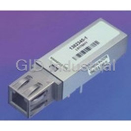
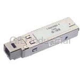
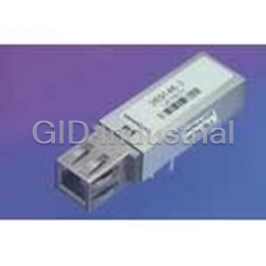
TE CONNECTIVITY 1382345-1
Description
TX/RX Optical Fiber 200Mbps 10-Pin
1382345-1
Part Number
1382345-1
Price
Request Quote
Manufacturer
TE CONNECTIVITY
Lead Time
Request Quote
Category
Optoelectronics and Displays » Fiber Optic Transceivers
Specifications
Manufacturer
TE Connectivity
Manufacturers Part #
1382345-1
Sub-Category
Fiber Optic Transceivers
Brand
AMP
Factory Pack Quantity
5
Datasheet
DDEController?Action=srchrtrv&DocNm=1654847&DocType=DS&DocLang=English&s_cid=1046.pdf
176 KiB

Extracted Text
PDF Datasheet 1654847 Revised 11-03 Only available as PDF at: http://www.tycoelectronics.com/fiberoptics ESCON/SBCON Multimode SFF MT-RJ Transceiver Product Facts ■ Fully compliant with ANSI X3.296-1997 SBCON ■ Complies with IBM Enterprise Systems Connection (ESCON) architecture ■ Single +3.3V power supply ■ Complies with Small Form Factor (SFF) Multi-Source Agreement (MSA) ■ High-density MT-RJ connector interface ■ High reliability 1300 nm optics ■ PECL and LVPECL compatible data interface ■ Wave Solder and Aqueous Wash compatible ■ UL 60950 recognized Tyco Electronics’ ESCON/SBCON providing an effective center line SFF MT-RJ Transceiver 1382345-1 is spacing of 0.55-inches from port to an LED based 1300 nm fiberoptic port, allowing the equipment designer transceiver module intended for use to double the port density of a given in ESCON and SBCON applications. product. The transceiver has a DC- The transceiver sends and receives coupled data interface that provides pre-encoded data over a pair of the highest degree of flexibility for 62.5 µm or 50 µm core multimode use in a wide variety of circuit optical fibers. The module, which architectures. It has been extensively operates from a single +3.3V power tested to comply with ANSI X3.296- supply, contains separate transmitter 1997 SBCON. Tyco Electronics also and receiver sections with PECL and offers a wide variety of Small Form LVPECL compatible data interfaces. Factor (SFF) and Small Form-factor (SFP) transceivers in both singlemode Technological advancements in and multimode. precision optical design and ASIC design have enabled Tyco Electronics The transceiver module meets Class to produce low cost SFF transceivers. 1 Eye Safety requirements, as defined Package style is the multi-sourced by IEC 60825-1. The module has 2 x 5 DIP style with integral MT-RJ been designed with grounding and connector interface. This new small shielding features that minimize EMI form factor is approximately half the susceptibility and radiated emissions. width of a duplex SC 1 x 9 module, Units are supplied with process plugs. Copyright 2003 by Tyco Electronics Corporation. All Rights Reserved. AMP and Tyco are trademarks. Dimensions are in millimeters with inches © (if shown) in brackets. Other products, logos, and Company names mentioned herein may be trademarks of their respective owners. 1 For drawings, technical data or samples, contact your Tyco Electronics sales engineer, call 1-800-522-6752, or visit our Website at: http://www.tycoelectronics.com/fiberoptics. Specifications subject to change. Consult Tyco Electronics for latest specifications. PDF Datasheet 1654847 Revised 11-03 Only available as PDF at: http://www.tycoelectronics.com/fiberoptics ESCON/SBCON Multimode SFF MT-RJ Transceiver (Continued) ESCON/SBCON Multimode Transmitter Performance Specifications: SFF MT-RJ Transceiver (T =0 to 70°C, V -V =3.135 to 3.465V DC) C CC EE Parameter Symbol Notes Min Typ Max Units Part Number Data Rate (NRZ) B — 8 — 200 Mb/s 1382345-1 Optical Output (avg.) P 1,2 -19.5 — -15 dBm OUT Extinction Ratio — 3 8 — — dB Optical Power at Logic P (“0”) — — — -45 dBm OUT Low “0” State Center Wavelength λ 4 1280 1320 1380 nm OUT Spectral Width (FWHM) ∆λ 4 — 130 175 nm Total Jitter t 5— — .8 ns TJ Output Rise Time t 4,6 — 1.2 1.7 ns TLH Output Fall Time t 4,6 — 1.2 1.7 ns THL Data Input Voltage V 7,8 V -1.84 — V -1.45 V IL CC CC Levels V 7,8 V -1.17 — V -0.880 V IH CC CC Data Input Current I — -350 — 10 µA IL Levels I — -10 — 350 µA IH Power Supply Voltage V - V — 3.135 3.3 3.465 V CC EE Supply Current I — — — 120 mA CC Operating Temperature T —0— 70 °C C Note: All optical measurements made through a short patch cable, between 2 and 5 meters in length, using 62.5 µm multimode fiber unless stated otherwise. 1. Meets Class I LED safety requirements of IEC 60825-1 when operated within the specified temperature and power supply ranges. Transmitter optical output power measured per TIA/EIA 455-95. 2. Specification applies to 0.275 NA 62.5/125 µm multimode fiber. 3. Extinction ratio measured per TIA/EIA 526-4A with a repeating K28.7 data pattern. 4. The output rise and fall time and spectral performance conform to ANSI X3.296-1997 SBCON. 5. Driven with a differential signal. 6. Measured from 20% to 80% points on rising and falling edge of transmitted waveform. 7. When V is used as the reference voltage. BB 8. Configured for LVPECL. Compatible with 10 K, 10 KH and 100 K ECL and PECL. Copyright 2003 by Tyco Electronics Corporation. All Rights Reserved. AMP and Tyco are trademarks. Dimensions are in millimeters with inches © (if shown) in brackets. Other products, logos, and Company names mentioned herein may be trademarks of their respective owners. 2 For drawings, technical data or samples, contact your Tyco Electronics sales engineer, call 1-800-522-6752, or visit our Website at: http://www.tycoelectronics.com/fiberoptics. Specifications subject to change. Consult Tyco Electronics for latest specifications. PDF Datasheet 1654847 Revised 11-03 Only available as PDF at: http://www.tycoelectronics.com/fiberoptics ESCON/SBCON Multimode SFF MT-RJ Transceiver (Continued) ESCON/SBCON Multimode Receiver Performance Specifications: SFF MT-RJ Transceiver (T =0 to 70°C, V -V =3.135 to 3.465V DC) C CC EE Parameter Symbol Notes Min Typ Max Units Part Number Data Rate (NRZ) B — 8 — 200 Mb/s 1382345-1 Optical Input (avg.) Sensitivity P 1 — — -33 dBm IN Saturation Level — — — — -14 dBm Optical Wavelength λ — 1280 — 1380 nm IN Systematic Jitter t ——— 2 ns SJ Random Jitter t — — — 0.6 ns RJ Output Rise Time t 2 — — 1.3 ns TLH Output Fall Time t 2 — — 1.3 ns THL V 3V -1.1 — V -0.86 V OH CC CC Output Voltage Levels V 3V -1.86 — V -1.620 V OL CC CC Signal Detect Output SD Voltage Assert V 3V -1.1 — V -0.86 V A CC CC Deassert V 3V -1.86 — V -1.620 V D CC CC SD Power Levels (avg.) Assert P — — -36 dBm A Deassert P — -45 — — dBm D Hysteresis — — .5 — 4 dB SD Delay Time Assert — — 0 — 100 µs Deassert — — 0 — 350 µs Power Supply Voltage V- — 3.135 3.3 3.465 V CC V EE Supply Current I — — — 110 mA CC Operating Temperature T —0— 70 °C C Note: All optical measurements made through a short patch cable, between 2 and 5 meters in length, using 62.5 µm multimode fiber unless stated otherwise. 1. Receive Sensitivity measured at, or extrapolated to, 10E - 12 BER using a 200 MBd input signal with a 7 2 -1 code pattern. 2. Receiver electrical output rise and fall times measured from 20 to 80% points on rising and falling edge of waveform with 50 ohm load to V -2V. CC 3. Measured with a 50 ohm load to V -2V. CC Absolute Maximum Ratings: Parameter Symbol Units Min Max Storage Temperature T °C -40 85 S Lead Soldering Limits/Time — °C/s — 240/10 Data Input Voltage V V -0.5 V INPUT CC Differential Input Voltage V V — 2.0 DIFF Supply Voltage V -V V -0.2 5.0 CC EE Copyright 2003 by Tyco Electronics Corporation. All Rights Reserved. AMP and Tyco are trademarks. Dimensions are in millimeters with inches © (if shown) in brackets. Other products, logos, and Company names mentioned herein may be trademarks of their respective owners. 3 For drawings, technical data or samples, contact your Tyco Electronics sales engineer, call 1-800-522-6752, or visit our Website at: http://www.tycoelectronics.com/fiberoptics. Specifications subject to change. Consult Tyco Electronics for latest specifications. PDF Datasheet 1654847 Revised 11-03 Only available as PDF at: http://www.tycoelectronics.com/fiberoptics ESCON/SBCON Multimode SFF MT-RJ Transceiver (Continued) Transceiver Pin Descriptions Package Outline Drawing Notes: 1. This figure describes the package outline, mounting studs, pins and their relationships to each other. 2. Toleranced to accommodate round or rectangular leads. 3. All 12 pins and posts are to be treated as a single pattern. 4. The MT-RJ optical connector has a 750 µm fiber spacing. 5. Refer to the MT-RJ Transceiver Pin Out Diagram for additional information. 6. This transceiver is supplied with an EMI gasket that fits onto the nose-piece and ensures an intimate fit between the nose-piece and the MSA defined customer front panel cut-out shown in Figure 4. Please refer to the Tyco Electronics’ Customer Drawing number 1382345-1 for additional details on these gasket dimensions. Millimeters Inches Millimeters Inches Min. Typ. Max. Min. Typ. Max. Min. Typ. Max. Min. Typ. Max. A 13.59 0.535 L 3.56 0.140 B 9.53 0.375 M 10.16 0.400 C 12.40 0.488 N 13.97 0.550 D 7.59 0.299 P 9.53 0.375 E 4.57 0.180 Q 48.72 1.918 F 7.11 0.280 R 36.42 1.434 G 17.78 0.700 ØS 0.97 1.07 0.038 0.042 ØH 0.41 0.61 0.016 0.024 T 1.02 0.040 J 1.78 0.070 U 0.25 0.010 K 7.12 0.280 V 3.30 0.130 Important: PLEASE SEE THE TYCO ELECTRONICS’ CUSTOMER DRAWING 1382345-1 FOR TRANSCEIVER HOUSING DIMENSIONS AND TOLERANCES. DRAWINGS CAN BE OBTAINED ON OUR WEBSITE AT: http://www.tycoelectronics.com OR CALL TYCO ELECTRONICS’ FAX SERVICE AT 1-800-522-6752. Copyright 2003 by Tyco Electronics Corporation. All Rights Reserved. AMP and Tyco are trademarks. Dimensions are in millimeters with inches © (if shown) in brackets. Other products, logos, and Company names mentioned herein may be trademarks of their respective owners. 4 For drawings, technical data or samples, contact your Tyco Electronics sales engineer, call 1-800-522-6752, or visit our Website at: http://www.tycoelectronics.com/fiberoptics. Specifications subject to change. Consult Tyco Electronics for latest specifications. PDF Datasheet 1654847 Revised 11-03 Only available as PDF at: http://www.tycoelectronics.com/fiberoptics ESCON/SBCON Multimode SFF MT-RJ Transceiver (Continued) Pin-Out Description: Symbol Pin No. Function Two Front Mounting Studs Provided for mechanical attachment to the PCB and ensure mechanical strength. The holes on the PCB that they attach to must be connected to chassis ground. Four Holes for Signal Connect to signal ground. Grounding Leads V 1 Receiver Signal Ground. Connect to receiver signal ground plane. EEr V 2 Receiver Power Supply. CCr Signal detect. SD 3 Normal Operation: Logic “1” Output. Fault Condition: Logic “0” Output. RD- 4 Received Data Out Bar. No internal terminations are provided. RD+ 5 Received Data Out. No internal terminations are provided. V 6 Transmitter Power Supply. CCt V 7 Transmitter Signal Ground. EEt No internal connection is provided. Transmitter Disable Input. V 8 DIS Optional feature for laser based products only. Transmitter Data In and Data In Bar. No internal terminations are provided. TD+ 9 See recommended circuit schematic. TD- 10 Transmitter Data In Bar. No internal terminations are provided. See recommended circuit schematic. Note: 1. VEEr and VEEt are connected together inside the transceiver module. Regulatory Compliance: Agency Test Method Listing Document EN60825-1:1994_A11:1996 TUV Product Services EN60825-2:1994+A1 LED Class I TUV EN60950:1992+A1+A2+A3+A4+A11 Protection Class III TUV Certification Number: B020546940002 UL/ UL60950 E141081 ESD Testing: Test Test Method Procedure ESD1 JEDEC/EIA JESD22-A114-A Pulses applied to each pin and Ground at 1 KV (C=100 pF, R=1500 ohm - Human body model) ESD2 25 KV maximum air discharge 40 discharges are applied per DUT (10 at each of the top, (simulates human body discharge into nose, right, and left). Each module is tested with both a DUT) power ON and OFF. Related Documents: ESCON/SBCON Multimode SFF MT-RJ Transceiver Application Specification #114-13083 Copyright 2003 by Tyco Electronics Corporation. All Rights Reserved. AMP and Tyco are trademarks. Dimensions are in millimeters with inches © (if shown) in brackets. Other products, logos, and Company names mentioned herein may be trademarks of their respective owners. 5 For drawings, technical data or samples, contact your Tyco Electronics sales engineer, call 1-800-522-6752, or visit our Website at: http://www.tycoelectronics.com/fiberoptics. Specifications subject to change. Consult Tyco Electronics for latest specifications. PDF Datasheet 1654847 Revised 11-03 Only available as PDF at: http://www.tycoelectronics.com/fiberoptics ESCON/SBCON Multimode SFF MT-RJ Transceiver (Continued) Figure 3: MSA Recommended Circuit Board Layout Notes: 1. This figure describes the recommended circuit board layout for the MT-RJ Transceiver placed at a 0.550 inch spacing. 2. The shaded areas are keep-out areas reserved for housing standoffs. No metal traces or Ground connection in keep-out areas. 3. The 10 pin module implementation requires only 16 PCB holes. 4. These four holes for signal grounding leads must be connected to signal ground on the PCB. 5. Solder Posts should be soldered to the PCB for mechanical strength and these PCB holes should be connected to chassis ground. Millimeters Inches Millimeters Inches Min. Typ. Max. Min. Typ. Max. Min. Typ. Max. Min. Typ. Max. A 13.34 0.525 M 9.59 0.378 B 7.59 0.299 N 10.16 0.400 C 4.57 0.180 P 13.97 0.550 D 7.11 0.280 ØQ 2.29 0.090 E 17.78 0.700 R 3.56 0.140 ØF 0.71 0.81 0.91 0.028 0.032 0.036 ØS 1.3 1.4 1.5 0.051 0.055 0.059 G 1.78 0.070 T 6.00 0.236 H 7.12 0.280 U 3.00 0.118 J 3.08 0.121 V 3.00 0.118 K 2.00 0.079 ØW 1.3 1.4 1.5 0.051 0.055 0.059 L 2.00 0.079 ØX 2.29 0.090 Copyright 2003 by Tyco Electronics Corporation. All Rights Reserved. AMP and Tyco are trademarks. Dimensions are in millimeters with inches © (if shown) in brackets. Other products, logos, and Company names mentioned herein may be trademarks of their respective owners. 6 For drawings, technical data or samples, contact your Tyco Electronics sales engineer, call 1-800-522-6752, or visit our Website at: http://www.tycoelectronics.com/fiberoptics. Specifications subject to change. Consult Tyco Electronics for latest specifications. PDF Datasheet 1654847 Revised 11-03 Only available as PDF at: http://www.tycoelectronics.com/fiberoptics ESCON/SBCON Multimode SFF MT-RJ Transceiver (Continued) Figure 4: MSA Recommended MT-RJ Front Panel Opening Millimeters Inches Min. Typ. Max. Min. Typ. Max. A 10.70 10.80 10.90 0.421 0.425 0.429 B 13.97 0.550 C 0.25 0.010 D 9.70 9.80 9.90 0.382 0.386 0.390 E 1.00 0.039 F 15.50 16.25 0.610 0.640 Copyright 2003 by Tyco Electronics Corporation. All Rights Reserved. AMP and Tyco are trademarks. Dimensions are in millimeters with inches © (if shown) in brackets. Other products, logos, and Company names mentioned herein may be trademarks of their respective owners. 7 For drawings, technical data or samples, contact your Tyco Electronics sales engineer, call 1-800-522-6752, or visit our Website at: http://www.tycoelectronics.com/fiberoptics. Specifications subject to change. Consult Tyco Electronics for latest specifications.
Frequently asked questions
How does Electronics Finder differ from its competitors?

Is there a warranty for the 1382345-1?
Which carrier will Electronics Finder use to ship my parts?
Can I buy parts from Electronics Finder if I am outside the USA?
Which payment methods does Electronics Finder accept?
Why buy from GID?

Quality
We are industry veterans who take pride in our work

Protection
Avoid the dangers of risky trading in the gray market

Access
Our network of suppliers is ready and at your disposal

Savings
Maintain legacy systems to prevent costly downtime

Speed
Time is of the essence, and we are respectful of yours
Related Products
TX/RX Optical Fiber 1250Mbps 1382350-1

TX/RX Optical Fiber 200Mbps 20-Pin SFP 1382410-1
TX/RX Optical Fiber 125Mbps 16-Pin 269037-1
TX/RX Optical Fiber 125Mbps 16-Pin 269038-1
TX/RX Optical Fiber 156Mbps 16-Pin 269047-1
TX/RX Optical Fiber 156Mbps 10-Pin DIP With Connector 269146-3
Request a Quote

The quote request has been received
Close

Facing challenges or have inquiries? Feel free to contact us!
Call Us +1-469-283-2440
What they say about us
FANTASTIC RESOURCE
One of our top priorities is maintaining our business with precision, and we are constantly looking for affiliates that can help us achieve our goal. With the aid of GID Industrial, our obsolete product management has never been more efficient. They have been a great resource to our company, and have quickly become a go-to supplier on our list!
Bucher Emhart Glass
EXCELLENT SERVICE
With our strict fundamentals and high expectations, we were surprised when we came across GID Industrial and their competitive pricing. When we approached them with our issue, they were incredibly confident in being able to provide us with a seamless solution at the best price for us. GID Industrial quickly understood our needs and provided us with excellent service, as well as fully tested product to ensure what we received would be the right fit for our company.
Fuji
HARD TO FIND A BETTER PROVIDER
Our company provides services to aid in the manufacture of technological products, such as semiconductors and flat panel displays, and often searching for distributors of obsolete product we require can waste time and money. Finding GID Industrial proved to be a great asset to our company, with cost effective solutions and superior knowledge on all of their materials, it’d be hard to find a better provider of obsolete or hard to find products.
Applied Materials
CONSISTENTLY DELIVERS QUALITY SOLUTIONS
Over the years, the equipment used in our company becomes discontinued, but they’re still of great use to us and our customers. Once these products are no longer available through the manufacturer, finding a reliable, quick supplier is a necessity, and luckily for us, GID Industrial has provided the most trustworthy, quality solutions to our obsolete component needs.
Nidec Vamco
TERRIFIC RESOURCE
This company has been a terrific help to us (I work for Trican Well Service) in sourcing the Micron Ram Memory we needed for our Siemens computers. Great service! And great pricing! I know when the product is shipping and when it will arrive, all the way through the ordering process.
Trican Well Service
GO TO SOURCE
When I can't find an obsolete part, I first call GID and they'll come up with my parts every time. Great customer service and follow up as well. Scott emails me from time to time to touch base and see if we're having trouble finding something.....which is often with our 25 yr old equipment.
ConAgra Foods